Myray RX DC User manual

Technical manual
cod. 97070012 rev. 4
RX DC
After Sales Service - Plant Via Bicocca 14/c 40026 Imola (BO)
Italy - Tel. ++39 0542 653441 - Fax ++39 0542 6 5 3 5 9 6
E-mail: [email protected]
Stabilimento / Plant
Via Bicocca 14/c - 40026 Imola (Bo) Italy
Tel. (+39) 0542 653441 - Fax (+39) 0542 653555


1
GB INSTALLATION
Contents
1. General safety precautions.......................................................................................................................................3
2. Packaging.................................................................................................................................................................3
2.1. Dimensions and contents................................................................................................................................3
2.2. Handling and storage......................................................................................................................................3
3. Before installation....................................................................................................................................................4
3.1. Mechanical specifications required.................................................................................................................4
3.2. Central control unit power supply .........................................................................................................................4
3.3. Wiring connection between central control unit and generator light ..............................................................4
4. Installation ................................................................................................................................................................5
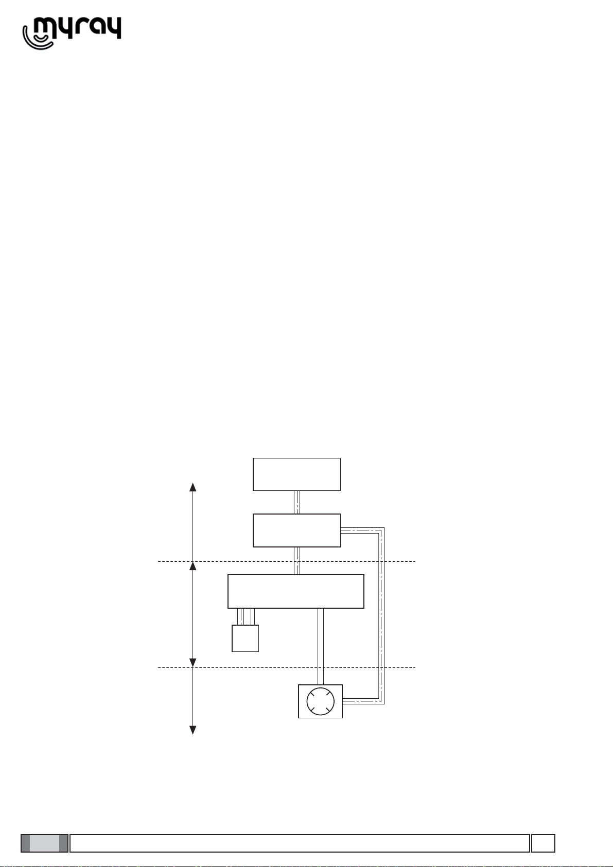
4.1. Positioning the x-ray unit’s structure...............................................................................................................5
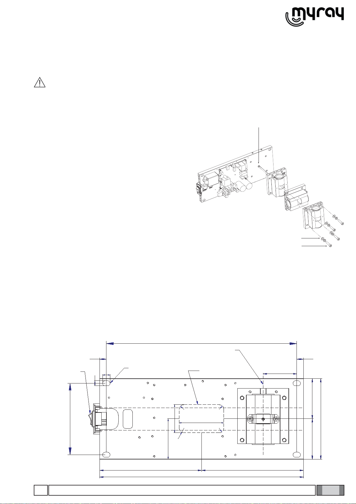
4.2. Wall-mounted plate for supporting the x-ray unit ............................................................................................5
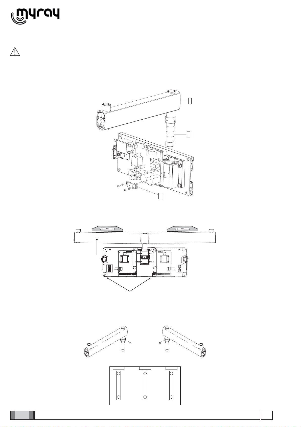
4.3. Extension arm.................................................................................................................................................6
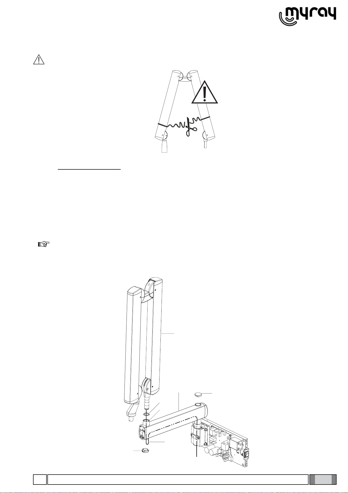
4.4. Installing the double pantograph arm .............................................................................................................7
4.5. Installing the generator ...................................................................................................................................9
4.6. Installing the collimator ...................................................................................................................................9
4.7. Balancing the double pantograph arm..........................................................................................................10
4.8. Adjusting the double pantograph arm end-stops ..........................................................................................10
4.9. Wall-mounted plate wiring connections.........................................................................................................11
4.10. Completion of wall-mounting plate and holder for hand-held. ....................................................................12
5. Factory settings......................................................................................................................................................13
6. Turning on...............................................................................................................................................................13
6.1. Turning The X-ray equipment on and off.......................................................................................................13
6.1.1. Turning on the basic X-ray unit........................................................................................................13
6.1.2. Turning on the handheld...................................................................................................................14
6.1.3. Control panel....................................................................................................................................14
6.1.4. Automatic handheld shut off.............................................................................................................15
6.1.5. Hand-held stand-by time ..................................................................................................................15
7. Checking the set parameters ................................................................................................................................16
8. Batteries and charge level status ..........................................................................................................................17
9. Position of the patient............................................................................................................................................17
10. Putting the x-ray unit cone into the required position .........................................................................................17
11. Position of the X-ray plate or sensor....................................................................................................................18
12. Checking the exposure time on the display.........................................................................................................19
13. Procedure to be followed when taking the x-ray..................................................................................................19
14. Technician and user setup menu .........................................................................................................................20
15. Actuator unit .........................................................................................................................................................22
16. Control unit card Code 97660515.........................................................................................................................23
17. Basic head control card Code 97660514 .............................................................................................................24
18. Actuator control card Code 97660591..................................................................................................................27
19. X-ray head............................................................................................................................................................28

2GB
INSTALLATION

3
-10 C°
70 C° RH
10% ÷ 90%
P
500 hPa ÷ 1060 hPa
5
4
3
2
1
GB INSTALLATION
INSTALLATION
1. General safety precautions
Cefla Sc - Cefla Dental Group guarantees the safety, reliability and performance of the equipment under the following
conditions:
• Installation and technical service is performed by authorized technicians using Cefla Sc - Cefla Dental Group original
spare parts.
• The electrical system in the dental surgery corresponds to standards I.E.C. 60364-7-710;V2 (Standards regarding
electrical systems in a medical environment) or equivalent standards currently in force in the country where the equi-
pment is installed.
• The place where the x-ray unit is installed must comply with official directives regulating radiation in the country where
the equipment is used.
• The equipment is operated as directed in the instructions manual..
This device complies with part 15 of the FCC Rules. Operation is subject to the following two conditions: (1) This device
may not cause harmful interference, and (2) this device must accept any interference received, including interference
that may cause undesired operation.
This equipment has been tested and found to comply with the limits for a Class B digital device, pursuant to part 15 of
the FCC rules. These limits are designed to provide reasonable protection against harmful interference in a residential
installation. This equipment generates, uses and can radiate radio frequency energy and, if not installed and used in
accordance with the instructions, may cause harmful interference to radio communications
Changes or modifications not expressly approved by the party responsible for compliance could void the user’s autho-
rity to operate the equipment.
2. Packaging
2.1. Dimensions and contents
• DIMENSIONS: 103X53X35 CM
• WEIGHT: 35 KG
• CONTENTS:
- Documentation and guarantee
- Disposable jig for installation
- Kit
- Wall back-plate (if requested)
- Wall-mounted plate
- Generator
- Tube
- Extension
- Collimator
- Double pantograph arm
2.2. Handling and storage
Indications regarding storage, handling and unpacking are given on the outside of the
cardboard packaging.
These indications must be strictly observed.
1) The package must be kept upright in the direction indicated by the arrows at all times
during handling and storage.
2) Avoid banging the package.
3) Keep the package free from damp.
4) Do not use hooks to handle the package.
5) A nameplate indicates the required ambient conditions for storage.
a) temperature from -15° to 50° C.
b) relative humidity from 10 to 90%
c) atmospheric pressure from 500 to 1060 hPa.

4
RX
LP
a
b
c
d
e
f
GB
INSTALLATION
3. Before installation
3.1. Mechanical specifications required
If the wall is thin (hollow bricks or similar), use the backplate (part no. 99930887) to be mounted on the wall or placed
on the side of the wall opposite the wall where the unit is to be installed.
Decide on a suitable system for fixing the plate according to the characteristics of the wall and its ability to resist a pull
force of 220 Kg applied at each anchorage point.
If the wall is made of cement or solid bricks, use the wall plugs supplied.
Alternatively we recommend using the “FISHER” chemical wall plugs which include:
• Braid type injection insert (item FIP 16X85).
• Threaded bar with bar and washer (item FIP 16M, 8X110).
• Chemical fixer (item FIP C 150).
3.2. Central control unit power supply
The supply line running to the central control unit must be 3x2.5 mm and protected by a bipolar circuit breaker which
conforms to the relevant electrical codes (10 A, 250 V, breaking power at least 6000 A, distance between contacts at
least 3 mm).
The colour of the three conductors (LINE, NEUTRAL and GROUND) must correspond to that established by regula-
tions.
3.3. Wiring connection between central control unit and generator light
This connection enables the generator light (optional) located outside the surgery to be turned on.
To connect the LP generator light to the central control unit, use 2 conductors having a cross-section of 0.5 mm (see
paragraph 4.8.).
LP light supply: 230V - 3x2.5 mm line.
Legenda:
SUPPLY LINEa) CIRCUIT BREAKER 10 Ab) CENTRAL CONTROL UNITc) OPTIONALd) SUPPLIEDe) NOT SUPPLIEDf)

5
SCATOLA ALLACCIAMENTI
A
MURO
ASSE BRACCIO
RADIOGRAFIC
O
POSIZIONE FISSAGGI
A
MURO
INTERRUTTOR
E
GENERAL
E
152.5
406.4
71.7
435
217.5 217.5
172
85.5
86.5
16
11
14.3
14.3
60
95
R10
R10
R10
R10
86
A
B
C
f
d
GB INSTALLATION
4. Installation
The x-ray unit must be installed by a qualified technician in compliance with the installation instructions given below as
regards both the mechanical and electrical parts.
WARNING!
Always check that the voltage indicated on the generator’s nameplate corresponds to that for the electrical
system.
Figure A
Figure POSITIONING
4.2. Wall-mounted plate for supporting the x-ray unit
Figure A
Determine the position of the x-ray unit by using the INSTALLATION JIG.•
• Position the wall-mount plate with the bottom holes at a height of approx. 120 cm from the floor.
• First check that the plate is at the correct height and perfectly horizontal and then mark out the four points where it is
to be fixed on the wall. Drill the holes and install the most suitable type of fastening system according to the characte-
ristics of the wall (see paragraph 3.1).
• Pass the supply cable through one of the holes in the wall-mount plate and fix this to the wall by partially tightening
the top and bottom screws.
MAIN
SWITCH
POSIZIONE
FISSAGGI A
MURO
ASSE BRACCIO
RADIOGRAFICO
SCATOLA
ALLACCIAMENTI
A MURO
4.1. Positioning the x-ray unit’s structure
Figure POSITIONING
Block the middle clamp in the opening provided (d) accor-• ding to which of the three positions available the structure
needs to be placed in:
A – PRESET CONFIGURATION WITH WALL-MOUNTED
STRUCTURE SET HORIZONTALLY TO THE RIGHT.
B - WALL-MOUNTED STRUCTURE SET VERTICALLY
DOWNWARD.
C - WALL-MOUNTED STRUCTURE SET HORIZONTALLY
TO THE LEFT.
• Secure the pin to the plate using the srews (f) and washers
(e) provided.

6
c
a
b
c
d
b
ab
a
GB
INSTALLATION
4.3. Extension arm
WARNING!
Do not lubricate the pin of the extension arm: the wall-mounted plate is provided with self-lubricating bushings.
Figure B
• Insert the pin (b) of the extension arm (c) in the hole provided in the wall-mounted plate.
• Take the clutch (a) from the kit, install it on the plate using the corresponding screws and adjust the arm (c) as requi-
red.
Figure C
• Use a spirit level to check that the arm (c) is slightly tilted upwards (approx. 1°). If necessary add a shim to the plate
near the bottom wall plugs (d).
• Fully secure the plate.
Figure D
• If the x-ray unit is installed in one of the corners of the dental surgery, make sure the extension arm cannot rotate too
far (90°) by installing the two end-stop pins (included in the kit) on the x-ray unit itself.
• Find the right position for installing the pair of pins (a, b) and insert them in the holes provided using a hammer.
Figure B
Figure C
Figure D

7
c
f
i
m
g
g
GB INSTALLATION
4.4. Installing the double pantograph arm
WARNING!
The arms are supplied secured together by a belt.
This belt should not be removed until the two free ends of the arms have been connected to their corresponding
attachments: the extension arm (already secured to the wall) and x-ray head.
If the belt is loosened before fixing the arms in place, releasing them abruptly could damage them and the
operator risks being injured.
Figure E
• Take the washer (f) from the kit and position it at point (i) corresponding to the extension arm (c).
• Pass the cable (m) of the pantograph arm (e) through the extension arm (c) so that it comes out of the hole below.
• Install the pantograph arm (e) on the extension arm (c)
NOTE:
The extension arm’s bushing is self-lubricating.
Do not lubricate the pin of the double-pantograph arm.
• Pass the cable (m) through the inside of the extension arm (c) so that it comes out of the wall-mounted plate.
• Install the plugs (g) in the corresponding holes in the extension arm (c). Figure E

8
a
c
q
p
L
j k
n
o
H
GB
INSTALLATION
Figure F
Take the grubscrew used to stop rotation (o) from the x-ray unit kit and tighten it at point H (tighten it fully and then• loosen by ½ turn).
NOTE:Turn the pantograph arm to check that the adjustment has been made properly.
Take the clutch assembly (friction element, screw and 4 curved washers) from the x-ray unit kit and install it at point• L. NOTE: Insert the curved washers (j) and the friction element (k) as indicated in figure F.
NOTE: The friction element (k) can be placed in the correct position (vertical cut) by inserting a screwdriver
in the hole provided for the screw (n).
Figure G
• Adjust the clutch which has just been installed.
NOTE:Turn the pantograph arm during the adjustment to check that the clutch is providing the correct
amount of friction.
• Install the plugs (p) on the extension arm (c).
• Attach the adhesive bumper (q) (supplied in the kit) in the centre of the plug at the point indicated in the diagram.
Figure H
• There are 2 end-stop screws in the wall-mounted plate to which Loctite has been applied to provide friction. These
have been adjusted according to the length of the extension arm supplied.
NOTE: Work on the screw itself (a) in order to make the extension arm stop before or after.
Figure F
Figure G
Figure H

9
a
b
c
d
d
a
GB INSTALLATION
4.5. Installing the generator
Figure I
• Take the generator out of the packaging.
• Insert the pin (a) in the sleeve making sure the respective openings match and secure with the screws (b) provided.
• Insert the power cable in the generator’s pin and run it out of the opening (c) provided.
• Lastly, put on the two side covers montare (d).
4.6. Installing the collimator
Figure L
• Take the collimator (a) out of the packaging.
• Insert it in the generator and block it in place by turning clockwise.
Figure L
Figure I

10
n
a
b
i
c
m
g
f
ed
h
l
B
b
B
a
c
d
GB
INSTALLATION
4.7. Balancing the double pantograph arm
Figure M
If the double pantograph arm does not stay in a stable position, adjust the spring tension by using an 8mmAllen wrench
about 20cm long.
• To adjust the arm (a) connected to the extension: position it as shown in the figure and place the wrench at point A.
NOTE:
TIGHTEN (clockwise) if the arm tends to move down.
LOOSEN (anti-clockwise) if the arm tends to move up.
• To adjust the arm (b) connected to the generator: put the 2 covers (c) and (d) on the front pivot point, move the arm
(b) into a horizontal position and insert the key in point B.
NOTE:
TIGHTEN (clockwise) if the arm tends to move down.
LOOSEN (anti-clockwise) if the arm tends to move up.
4.8. Adjusting the double pantograph arm end-stops
Figure N
If the end-stops of the double pantograph arm need to be adjusted, work on the screws (i -l - m - n) shown in the
diagram.
NOTE:
To adjust the screw (n) on the articulated joint of the extension side place the relevant arm (a) in a horizontal position.
Figure M
Figure N

11
3
4
1
2
N
L
N
L
LINE
L
N
230 V
BROWN
BLUE
YELLOW/GREEN
1
2
3
4
5
6
VIOLET
GREY
BROWN
BLUE
VIOLET
GREY
1
2
3
4
F2
K1
K6
K2
K1
LP
GB INSTALLATION
4.9. Wall-mounted plate wiring connections
Figure O
Connect the power cable (LINE) to terminal K2, observing the following positions:• L - SUPPLY (BROWN WIRE)
- GROUND (YELLOW/GREEN wire)
N - NEUTRAL (BLUE wire)
• Connect the generator’s power cable to the respective connectors, observing the following positions:
K6 - brown wire and blue wire.
K5 - white wire – black wire – red wire – green wire – purple wire.
Eyelet connectors - Both found near the card (see figure).
NOTE: Place the excess cable under the card..
• Connect the 2 control wires (0.5 mm cross-section) for the “generator on” indicator light (LP) to connector K3.
Figure O

12
c
ab
b
d
f
GB
INSTALLATION
4.10. Completion of wall-mounting plate and holder for hand-held.
Figure P and Figure Q
• Pick up the cover (a) and place it on the wall-mounting plate fully tightening the grub screws (b) provided and pre-
screwed on the plate.
• Place the cover (c) in the area shown in the figure. The door (d) will automatically close when the controller is clo-
sed.
• Put the controller label in the required area (e) on the cover directed according to the position in which he wall-moun-
ting plate is installed.
• To install the handheld’s mount (f), refer to the INSTALLATION TEMPLATES.
Figure P
Figure Q

13
B
GB INSTALLATION
5. Factory settings
The x-ray unit is supplied with the following factory settings:
• Anode current: 7 mA (NORM mode).
• Sensitivty: level 19.
• Handheld stand by: 5 minutes
• Patient’s built: adult (ADULT symbol selected).
• Collimator presence signaled on the display (collimator symbol off if the rectangular collimator is not turned on in the
head).
• Exposure times according to standard R20: 0,010-0,011-0,012-0,014-0,016-0,018-0,020-0,022-0,025-0,028-0,032-
0,036-0,040-0,045-0,050-0,056-0,063-0,071-0,080-0,090-0,100-0,110-0,125-0,140-0,160-0,180-0,200-0,220-0,250-
0,280-0,320-0,360-0,400-0,500-0,560-0,630-0,710-0,800-0,900-1,000.
NOTE:
These times complywith currentstandards I.E.C. 60601-2-7(1999) and theISO 497 seriesR’20 recommendations
and CANNOT BE MODIFIED.
6. Turning on
6.1. Turning The X-ray equipment on and off
6.1.1. Turning on the basic X-ray unit
The control unit is turned on and off with the main switch (A), as illustrated in the figure below. The switch lights up
when the control unit is energized. Whenever turned on, the equipment performs an operational test that takes a few
seconds. Once the test has been completed, a buzzer rings and the indicator light (B) on the X-ray generator lights
up at the same time.
NOTE: The exposure time and the parameters displayed when the unit is turned on are the last ones set before
the central control unit was turned off. If the central control unit is left untouched for a few minutes it will go into stand-by
mode. Simply press any key on the control panel to reactivate it.

14 GB
INSTALLATION
6.1.2. Turning on the handheld
The handheld is turned on by pressing any key, except for the one for x-ray emission. A buzzer rings to confirm the
apparatus has been turned on. The unit will be in the standard configuration described in detail in paragraph 3.1.3 and
then search for the base it works with.
If the base is off, the handheld will not indicate the field nor status “ready”. If the base is latter turned on, the handheld
will detect it within thirty seconds or by pressing any function key on the pushbutton panel.
Pause for coo-
ling
Field present for dialo-
ging with “base”
Tooth selec-
tion
Exposure time
and dose di-
splay
Battery char-
ge level
Patient’s
build
Graduated
bar for ther-
mal load
Fine adjustmen-
ts according to
scale
Collimator with
cylindrical beam
(rectangular col-
limator not tur-
ned on)
Time/dose unit
of measure
6.1.3. Control panel
As illustrated in the figure below, the handheld has four function keys and the exposure key.
Selection of
teeth zones
“Decrease” key
X-ray expo-
sure” key
Patient bui-
ld selection
X-ray expo-
sure indicator
light
“Increase”
key

15
GB INSTALLATION
The main functions of the keys on the handheld vary according to how they are pressed:
KEY BRIEFLY PRESSED (less than 3 sec.) PRESSED LONGER (more than 3 sec.)
Changes over from ADULT to CHILD
and vice versa (takes place when key
is released).
Saves, if permitted, the sensitivity of the new tme
selected. The memo icon ( ) lights up when the
data item can be saved.
Changes amongst the various types of
teeth to select the area to be examined. Displays the exposition time of the tooth in mGy
and, if the key is held down a few more seconds,
in mGy*cm2.
Increases the exposure times in steps,
according to the set scale. Increasesthescroll speedofthe valuesin increas-
ing order.
Increases the exposure times in steps,
according to the set scale. Increasesthe scrollspeed ofthe valuesin decreas-
ing order.
NO EFFECTS ARE OBTAINED IF THE
KEY IS PRESSED LESS THAN A SE-
COND.
STARTS X-RAY EXPOSURE (the button has to
be held down while the x-rays are being emitted,
“dead man” function).
NOTE: “Dead man” function: the system that starts x-ray exposure with the dedicated key on the wireless han-
dheld allows x-rays to be emitted only when the user presses and holds down the exposure key. X-ray emission will
stop if the key is released ahead of time.
NOTE: The function related to pressing the key briefly is performed by pressing the key which will activate the
function assigned to it. On the other hand, to perform the function carried out when the key is held down longer, press
the key until the relative function is started. The buzzer will ring shortly to signal the function has started.
6.1.4. Automatic handheld shut off
About one minute after the base is turned off the handheld automatically shuts off. Similarly, the handheld will automa-
tically shut off if it is far away or in any case outside the operating range for interfacing with the base.
6.1.5. Hand-held stand-by time
The entire x-ray unit will switch over to stand-by (even if the base is on) and the handheld will automatically shut off
after approximately five minutes of non-use to save battery power. Press any key, except for the “exposure” key, to turn
the handheld back on showing the last selection made by the user. To change the stand by time, refer to chapter 4
regarding the handheld’s “Advanced options”.

16 GB
INSTALLATION
7. Checking the set parameters
Before actually taking an exposure, make sure the exposure parameters for the examination in progress are correctly
set.
- Checking the collimator used.
The icon on the handheld’s screen should be on or off, depending on the operating mode selected:
ICON ON: indicates that the cylindrical collimator is activated.
ICON OFF:indicates the rectangular collimator is activated.
NOTE: After turning the collimator on or off, the preset exposure times and icon will automatically be modified
within a few seconds.
- Checking the set patient’s build.
- “Child” selected: indicates the x-ray unit is set for patients with small builds.
- “Adult” selected: Indicates the x-ray unit is set for patients with average-large builds.
To change the selection, press the relative button.
NOTE: After the change has been made, the preset exposure times will automatically be modified.
- Checking the set intraoral examination
Examination of upper molars
Examination of upper premolars/canine or rear “bite wing”
Examination of upper incisors or front “bite wing”
Examination of lower incisors
Small build
(CHILD)
Average/large build
(ADULT)

17
GB INSTALLATION
Examination of lower premolars/canine
Examination of lower molars
8. Batteries and charge level status
The handheld runs on two widely available AA alkaline batteries to assure sifficient stand-alone operation. The charge
level of the batteries is given on the screen as follows:
Battery fully charged (a symbol does not appear in the area that shows the battery charge level).
Battery half-charged.
Battery charge level low or almost dead (causing the handheld to automatically shut off).
The batteries should be removed from the handheld if it is not going to be used for an extended period.
9. Position of the patient
A positioner or alignment device specific for the selected image receiver should always be used to assure the x-rays
are correctly aligned regardless of the position the patient’s head is in.
10. Putting the x-ray unit cone into the required position
The x-ray unit cone is initially locked in place by an electric brake. To release the brake and turn the cone on the pivot
point, use only the touch-sensitive unlock areas (see figure below).
Hold down the unlock buttons to tilt the cone the extent desired by the dentist to take the exposure and then simply
release the unlock buttons to lock it in place.
NOTE: The cone should be firmly held in place with both hands while pressing the release buttons and
turning the cone on the pivot point.
Unlock button Unlock button

18 GB
INSTALLATION
11. Position of the X-ray plate or sensor
The parallel technique, where applicable, provides more accurate images in terms of size compared to the bisecting te-
chnique.A rectangular collimator, with 30 cm focus-skin distance, is always preferable to obtain better quality pictures.
To avoid exposing the image receiver only partly (whether it is a sensor or photostimulable phosphorus plate system)
an alignment device that gives rectangular collimators guidelines should be used. These lines are usually given on the
alignment ring.
Parallel technique
The x ray emission axis is perpendicular to the image receiver (for example a sensor or photostimulated• phosphor plate) which in turn is parallel with the tooth’s long axis.
As a result, the picture of the tooth will only be deformed by the divergence of the x rays in relation to the• focus spot.
Radiographic enlargement may reach up to 15%.• For some “special” pictures, for example occluded ones, it may be necessary to remove the rectangular col-• limator and use the round one if a positioner is not present.
INCISORS
INCISORS
CANINES
CANINES
PREMOLARS
PREMOLARS
MOLARS
MOLARS
UPPER
LOWER
Other manuals for RX DC
3
Table of contents
Other Myray Dental Equipment manuals
Popular Dental Equipment manuals by other brands

MIHM-VOGT
MIHM-VOGT HT-2/M/Zirkon-120 Original operating manual

Practicon
Practicon BFC3 Instructions for use

Schick
Schick Q3 Original instructions

Heraeus
Heraeus iBond Total Etch Instructions for use

Renfert
Renfert EASY view+3D Original instructions

Dentsply Sirona
Dentsply Sirona Spacefile Directions for use