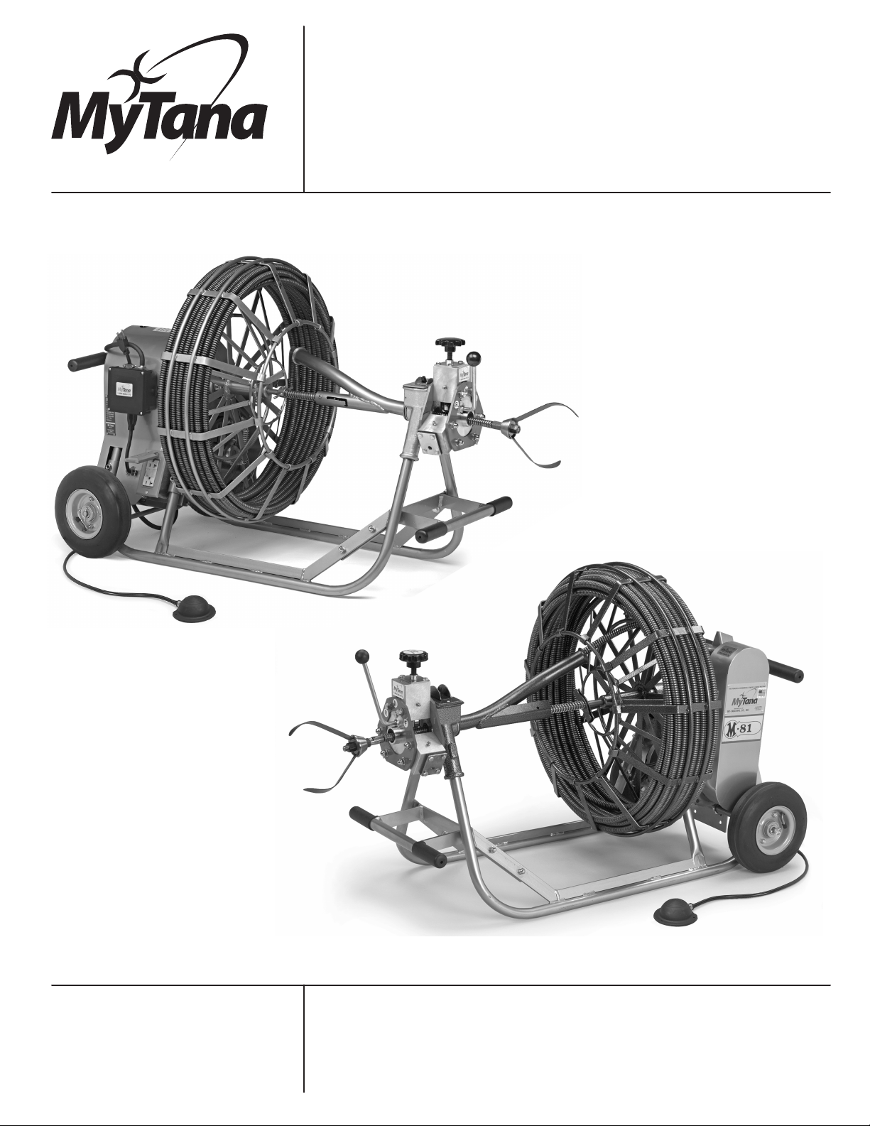
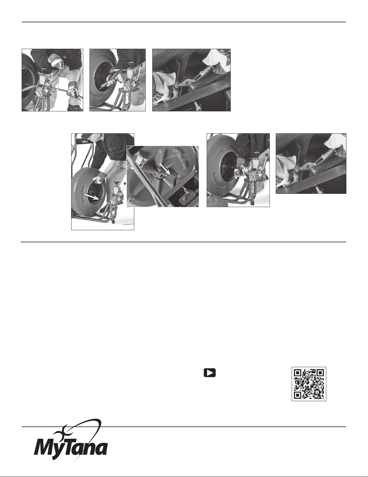
MyTana M844 User manual

Manufacturers of Quality
Sewer & Drain Cleaning
Equipment since 1957
1.800.328.8170
Factory Direct Customer Service
M –F 7am – 5pm CST
Competent • Polite • Clear
www.MyTana.com
746 Selby Ave • St. Paul MN, 55104
fax: 651.222.1739
M844
M81
M844 & M81
Owners Manual
041917

2
-IMPORTANT NOTICE-
THIS MACHINE IS NOT TO BE OPERATED BY ANYONE UNTIL HAVING
CAREFULLY READ THIS INSTRUCTION BOOK ON ITS USE.
IF ANYONE ELSE THAN THE ORIGINAL BUYER OF OUR EQUIPMENT
IS TO USE THE EQUIPMENT, THEN HE or SHE IS TO BE FURNISHED
WITH AN INSTRUCTION BOOK.
TO REQUEST NEW AND/OR ADDITIONAL INSTRUCTION BOOKS
PLEASE NOTIFY US AT:
MyTana Mfg. Co., Inc.
746 Selby Ave
St. Paul MN, 55104
(651) 222-1738 (800) 328-8170
STATE WHAT MODEL MACHINE AND WE WILL IMMEDIATELY MAIL
A COPY OF INSTRUCTIONS.
The model number of this machine is
M844 M81
__________________________________
This manual contains user information for both the M844 and M81 machines.
Take a minute to note which model you have in the space above.
Included you will find:
Set up and operating instructions
Troubleshooting information
A parts list for each model
Warranty information

3
Drive Spring Cleat Pin
Driving Rod
Figure 3
Figure 1
Gear Shaft
Figure 2
Assembly
Step 1
Mount reel onto machine by grasping it rmly and
lifting it up so that the back center of the hub aligns
with the main gearbox shaft. Slide reel all the way
onto shaft. (Figure 1)
Step 2
Fasten the drive spring at the back of the reel to the
driving arm (rod) which extends from the main shaft.
The diamond shaped piece at the center of the drive
spring simply slips over the pin at the top back side
of the driving arm. (Figure 2)
Step 3
Revolving “Feed” arm
Carefully pull end of cable out through open side of
reel. Holding revolving arm in one hand and cable in
the other hand, push cable through curved end of
arm in a twisting motion. Push cable up to front end
of revolving arm. (Figure 3)
Assembly and
Operating Instructions

4
Step 4
Insert the combined revolving arm and cable into
the opening in the head casting below the front
toggle switch. Then, at the other end of the
revolving arm, pull back on the center spring
loaded shaft of the arm and insert into the hole at
the front center hub of the reel.
uWith the new J-Lock style revolving arm
you can lock the center shaft back and out
or your way at anytime during assembly.
However, release the arm out of the J-Lock
in this step. (See Figure 4).
Step 5
Your machine is equipped with an air-actuated
foot switch, attach the air-hose to the air-switch
stem (on the M81 protruding from electrical box
next to motor; on the M844 protruding from the electrical
box mounted to belt guard) and lock it in place with the
pressure nut that is at the end of the hose.
uStep 5 is usually completed at the factory before your
machine is sent.
Step 6
If you ordered an Automatic Feed/Retriever, attach that to
the front casting of your machine at this time. The silver
bracket at the back, bottom side of the Auto Feed slips
under the ange of the front machine“head”casting. Then
secure into place by threading the top two bolts on the
Auto Feed into the two holes on the front, face side of the
head casting on the machine (See Figure 5). See additional
instructions for operations and maintenance of Automatic
Feed/Retriever.
The machine is now assembled except
for attaching a blade to cable.
uWait to attach blades to cable until you have
the machine in place at your pipe-opening or
clean-out. The blades are sharp and are potentially
dangerous if left on during transportation. Always
remove blades after you have completed the job.
Figure 5
Figure 4

5
Operation
NOTE: Before starting your rst job, please
read the paragraph on “Building up torque”
on page 7.
When operating the machine, place it about
3 feet from the opening in the pipe. An experi-
enced operator may nd it more comfortable to
vary the distance, but only slightly (See Figure 6).
Any of the single-unit blades may be used, but it
is best to use a blade much smaller than the inside
diameter of the pipe or sewer to begin the job.
When the desired blade has been attached to the
cable you are ready to start operation.
Remove the clean-out plug and insert the cable,
with blade attached, into the pipe by hand with a
twisting motion. When you have passed the bend,
continue to rotate and push the blade about 5 or
6 ft into the pipe, making sure it is not caught or
bound so that it can rotate freely. (Figure 7)
uDO NOT start machine before inserting
blade 5 to 6 ft into pipe.
Start Up
When starting the machine, the operator should have his
foot ready to press on the air-switch foot pedal.
You can aid the startup by rotating the reel with your hand
in a counter-clockwise direction while pressing on the
pedal. This allows for much easier starting and longer life for
the motor. (See Figure 8)
uThe front toggle switch must be in the “on”position
for the foot pedal to work.
The forward reverse switch should be in the
forward position, even when pulling (retrieving) the
cable out of a line.
Figure 6
Figure 8
ALL OPERATORS: Read the operating instructions
on the these pages before operating equipment.
3'
Figure 7
Always have blade
5 or 6 ft into pipe
and freely moving
before you start
motor
The machine always
rotates counter-clockwise
(Facing the reel from the
front of the machine).

6
Figure 10
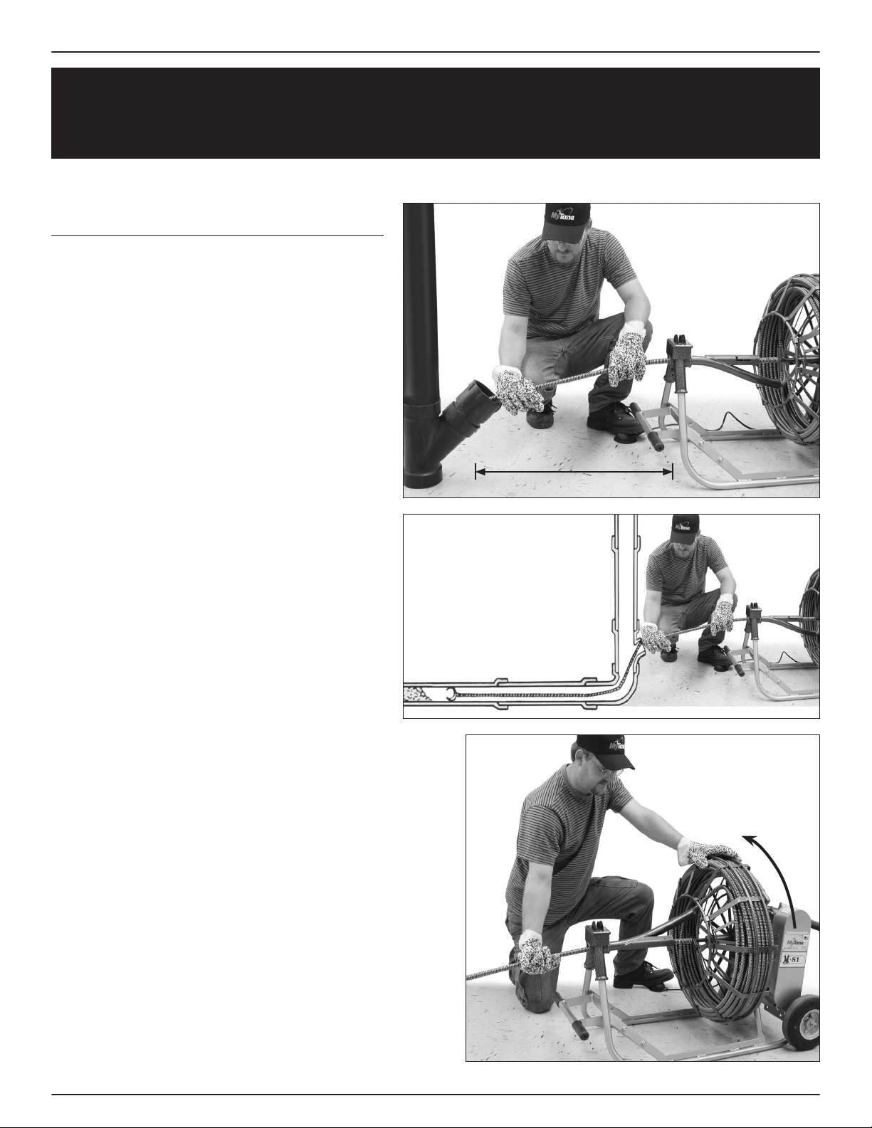
Always remember to stack the cable snugly against the
outer diameter of the reel while operating the machine
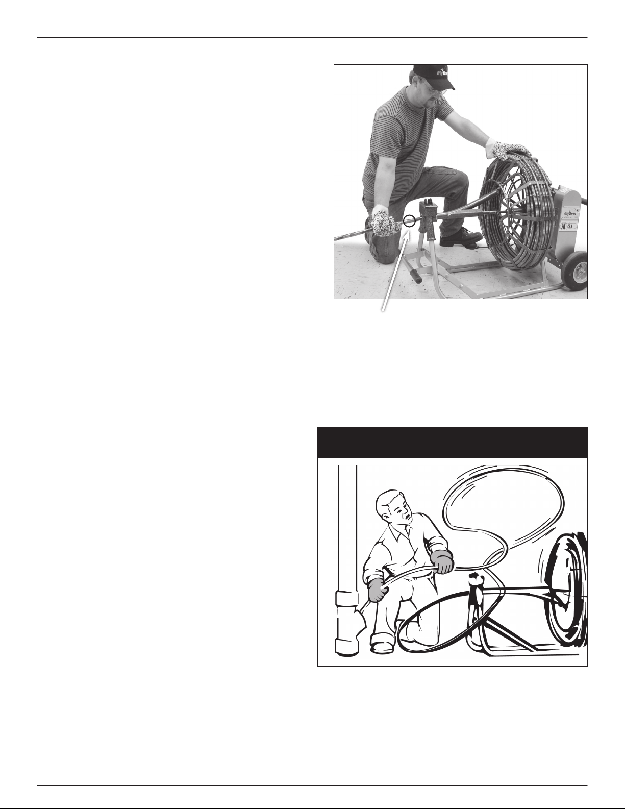
As you operate the machine, place one hand on the cable
close to the switch (See Figure 9 ) to prevent any throwing
of the cable.
Gently pull the cable out of the machine a little at a time.
You will nd that it will move itself into the sewer.
When the operator has had sucient experience, his
“touch”will tell him the extent of tension to allow the
cable before pulling back form the obstruction; however,
inexperienced operators should be cautious and allow the
cable only about 5 seconds to cut through. If the blade
doesn’t release, pull it away from the obstruction and
try again. The freed blades spin rapidly when torque is
released. Use the combined force of the reel rotation and
cable torque to optimize your cutting power. This action
will be more eective and will shorten the length of time
on the job.
Difficulties
If at anytime the cutting blades become stuck and cannot
be released, shut o machine immediately and hold cable
close to the switch to prevent the cable rom coming out
of the machine. Continue holding cable with one hand
and unhook the spring cleat with the other hand (See
Figure 10). Let the reel spin backwards, removing the
strain on the cable. After the reel stops, spin it backwards
a few more turns. This may release the obstructions that
can be wrapped around the cutting blades. When the
cable is released, pull the cable out of the pipe, clean o
any obstruction accumulated on the blades or cable, and
insert it into the sewer again, still using the smaller blades.
Larger blades can be used after the smaller ones have
been through the full length of the pipe.
Obstructions
When the blade hits an obstruction, it can be readily felt
by the operator. Give the blade a few seconds to release;
if it doesn’t, pull back the cable just enough to free the
blade, allowing it to rotate freely again. Continue this
until you have reached the end of the pipe. Withdraw the
cable gently and feed it into the machine, where the same
counter-clockwise rotation will re-wind it snugly into the
reel. SHUT OFF THE MOTOR AND CHANGE BLADES!
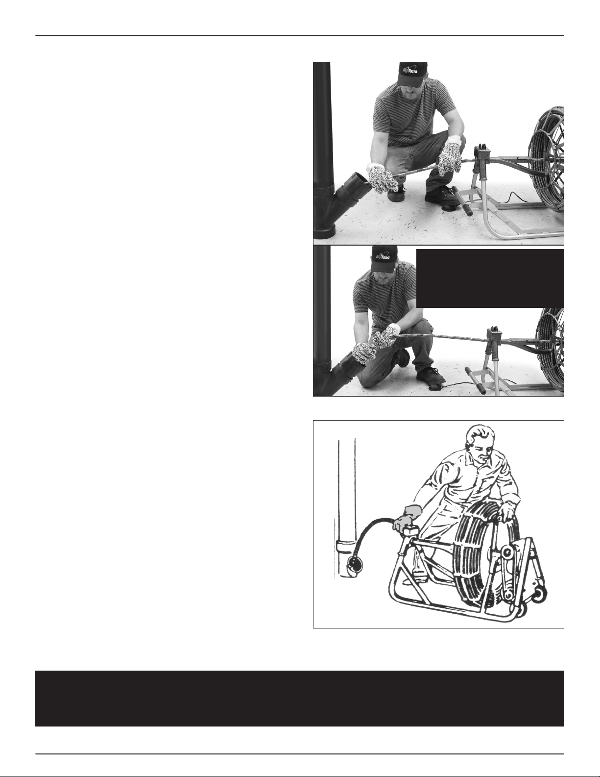
NEVER HOLD CABLE LIKE THIS.
IT IS DANGEROUS
HOLD AS IN FIGURE 9 (above)
Figure 9

7
After the rst opening is made, turn on the nearest faucet
so that water will ush the loosened debris. Allow the
water to run continuously during the entire job. Follow
the rst opening with slightly larger blades until you can
use a blade that will actually scrape the sidewalls of the
pipe or sewer.
Each job is a new problem in itself, and the operator will
master each situation as it arises. Mastering the operation
of the machine can be sped up by carefully following
these simple rules during and on-the-job operation.
DO NOT LEAVE MOTOR RUNNING UNATTENDED!
When reel is almost empty, tting should
be about in this location. Take apart and
push stub back into reel.
Figure 11
Building up Torque
As the reel revolves, it generates power and stores up
energy in the cable if the blade at the front of the cable
has been stopped by an obstruction.
When the rotating blade contacts an obstruction that it
cannot cut through quickly, or at all, the cable naturally
continues to wind up with the rotation of the reel. This
wind up builds up torque, or tension, which acts as a
powerful spring motor.
If too much tension is allowed in the cable, it will lash in
the operator’s hands or can whip wildly and dangerously
out of control (See Figure 12).
Torque build up is an extremely powerful force and
the operator must always be warned of its potential
danger.
NEVER LET THIS HAPPEN
CAUTION - READ CAREFULLY!!
Figure 12

1.800.328.8170
fax: 651.222.1739 www.MyTana.com
746 Selby Ave
St. Paul MN, 55104
Splicing Cables No welding necessary
NOTE: When ordering splicing cores or male
ends, please specify the size cable they are for.
1. When splicing, the ends of the cable should be
ground so that when put together it should hardly
be noticeable. DO NOT spread the cable if it is
dicult to start the core. Instead, grind the tip of the
core slightly, but ONLY THE TIP, as it must t tightly
into the cable.
2. Clamp one end of the cable vertically into a bench-
vise, with the end of the cable about 2”above
the vise. Screw half the core into the cable count-
er-clockwise. Now lower the same cable so that
the end will be even with the top of the vise, still
pointing upward, and so that only the exposed half
of the core is above the vise. Tighten the vise as
much as possible to prevent the core from being
unevenly divided when joining the other cable.
3. Turn the other cable (counter-clockwise) onto the
exposed half of the core, making sure that both ends
of cables t tightly against each other.
4. The same procedure applies when inserting the core
of a male end into a cable.
SPLICING cables get you bent out of shape?
See our how-to video
on this process at
YouTube.com/videoMytana
Reel Change Quick Guide
Disconnect backend
cable
Release revolving
arm
Change reels
Slide empty
reel off Slide new reel on
Unhook drive spring from cleat
on drive arm. No Belt!
Re-engage
revolving arm
Hook drive spring over
cleat on drive arm
This manual suits for next models
1
Table of contents
Other MyTana Industrial Equipment manuals