N.A.T. powerBridge NAMC-EXT Product manual

NAMC-EXT – Technical Reference Manual
NAMC-EXT
NAMC-EXT-PS
AMC Extender Module
Technical Reference Manual V1.6
HW Revision 1.5

NAMC-EXT – Technical Reference Manual
Version 1.6 © N.A.T. GmbH 2
The NAMC-EXT has been designed by:
N.A.T. GmbH
Konrad-Zuse-Platz 9
D-53227 Bonn-Oberkassel
Phone: ++49 / 228 / 965 864 - 0
Fax: ++49/ 228 / 965 864 - 10
Internet: http://www.nateurope.com

NAMC-EXT – Technical Reference Manual
Version 1.6 © N.A.T. GmbH 3
Disclaimer
The following documentation, compiled by N.A.T. GmbH (henceforth called N.A.T.),
represents the current status of the product´s development. The documentation is
updated on a regular basis. Any changes which might ensue, including those necessitated
by updated specifications, are considered in the latest version of this documentation.
N.A.T. is under no obligation to notify any person, organization, or institution of such
changes or to make these changes public in any other way.
We must caution you, that this publication could include technical inaccuracies or
typographical errors.
N.A.T. offers no warranty, either expressed or implied, for the contents of this
documentation or for the product described therein, including but not limited to the
warranties of merchantability or the fitness of the product for any specific purpose.
In no event will N.A.T. be liable for any loss of data or for errors in data utilization or
processing resulting from the use of this product or the documentation. In particular,
N.A.T. will not be responsible for any direct or indirect damages (including lost profits,
lost savings, delays or interruptions in the flow of business activities, including but not
limited to, special, incidental, consequential, or other similar damages) arising out of the
use of or inability to use this product or the associated documentation, even if N.A.T. or
any authorized N.A.T. representative has been advised of the possibility of such
damages.
The use of registered names, trademarks, etc. in this publication does not imply, even in
the absence of a specific statement, that such names are exempt from the relevant
protective laws and regulations (patent laws, trade mark laws, etc.) and therefore free
for general use. In no case does N.A.T. guarantee that the information given in this
documentation is free of such third-party rights.
Neither this documentation nor any part thereof may be copied, translated, or reduced to
any electronic medium or machine form without the prior written consent from N.A.T.
GmbH.
This product (and the associated documentation) is governed by the N.A.T. General
Conditions and Terms of Delivery and Payment.
Note:
The release of the Hardware Manual is related to a certain HW board
revision given in the document title. For HW revisions earlier than the one
given in the document title please contact N.A.T. for the corresponding older
Hardware Manual release.

NAMC-EXT – Technical Reference Manual
Version 1.6 © N.A.T. GmbH 4
Table of Contents
TABLE OF CONTENTS .......................................................................................... 4
LIST OF TABLES .................................................................................................. 5
LIST OF FIGURES................................................................................................ 5
CONVENTIONS.................................................................................................... 6
1INTRODUCTION ........................................................................................... 7
2OVERVIEW ................................................................................................... 9
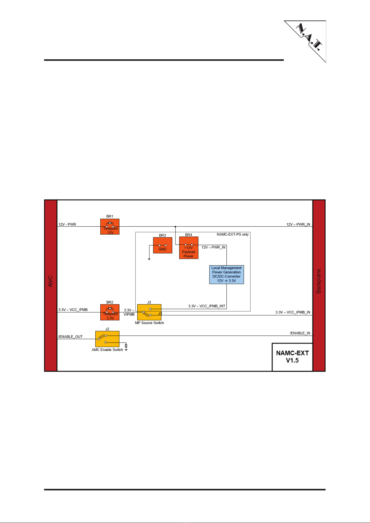
2.1 BLOCK DIAGRAM ......................................................................................... 9
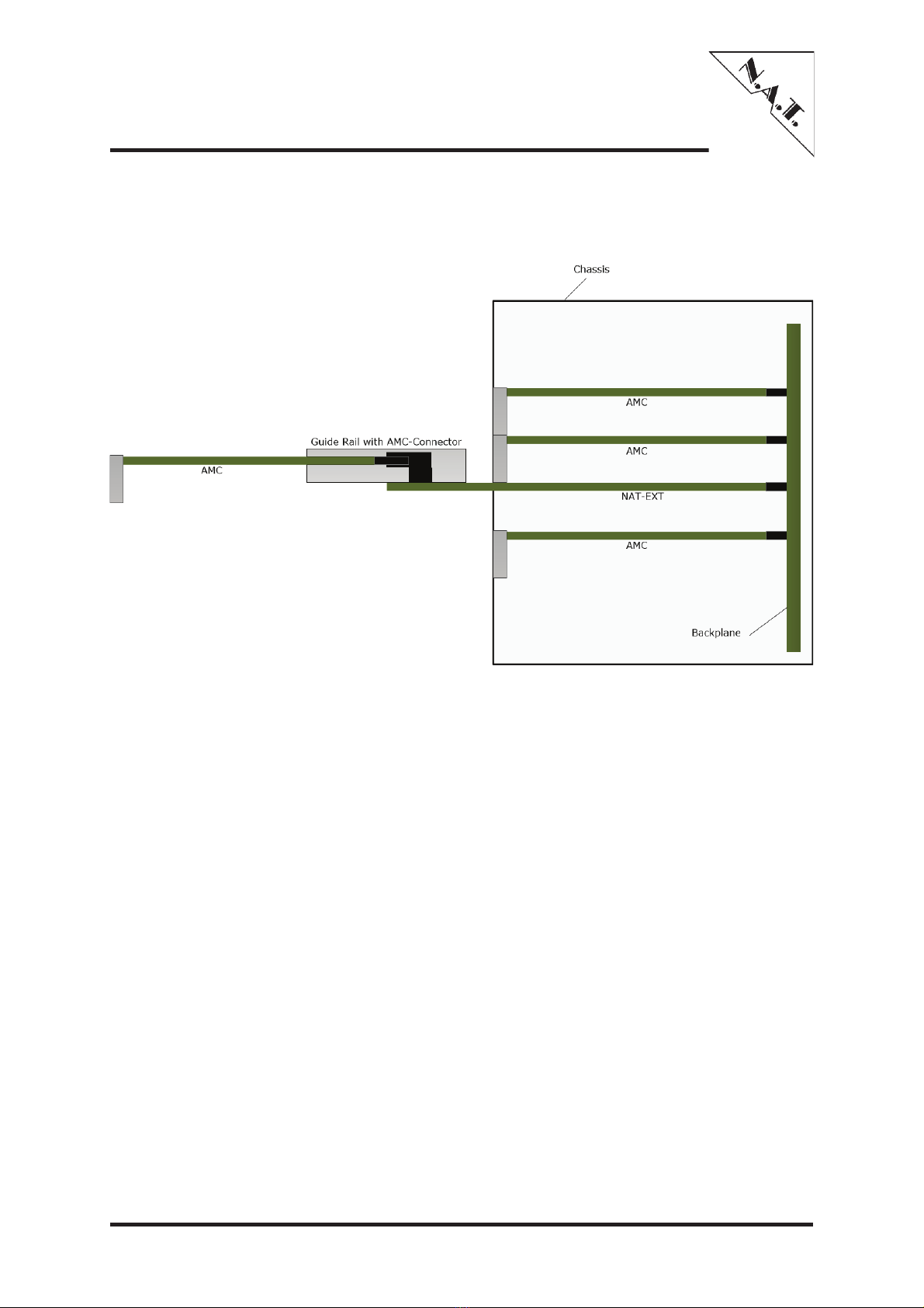
2.2 LOCATION DIAGRAM ....................................................................................10
2.3 DIMENSIONS .............................................................................................12
3BOARD FEATURES ...................................................................................... 13
3.1 BUS INTERFACE..........................................................................................13
3.2 POWER SUPPLY ..........................................................................................13
4HARDWARE ................................................................................................ 14
4.1 AMC PORT DEFINITION ................................................................................14
4.2 CONNECTORS,JUMPERS AND WIRE BRIDGES .......................................................15
4.2.1 J1/JP1: AMC Connectors ....................................................................16
4.2.2 Jumper JP2 ......................................................................................18
4.2.3 Jumper JP3 (NAMC-EXT-PS only) ........................................................18
4.2.4 Wire Bridges ....................................................................................19
4.3 TEST POINTS .............................................................................................19
5BOARD SPECIFICATIONS ........................................................................... 20
6INSTALLATION .......................................................................................... 21
6.1 SAFETY NOTE ............................................................................................21
6.2 INSTALLATION REQUIREMENTS ........................................................................21
6.2.1 Requirements ..................................................................................21
6.2.2 Power supply ...................................................................................21
6.3 STATEMENT ON ENVIRONMENTAL PROTECTION ......................................................22
6.3.1 Compliance to RoHS Directive ............................................................22
6.3.2 Compliance to WEEE Directive............................................................22
6.3.3 Compliance to CE Directive ................................................................23
6.3.4 Product Safety .................................................................................23
6.3.5 Compliance to REACH .......................................................................23
7KNOWN BUGS / RESTRICTIONS................................................................. 24
APPENDIX A: DOCUMENT’S HISTORY ............................................................... 25

NAMC-EXT – Technical Reference Manual
Version 1.6 © N.A.T. GmbH 5
List of Tables
Table 1: List of used abbreviations ...................................................................... 6
Table 2: AMC Port Definition for N.A.T. AMC Modules ............................................14
Table 3: J1/JP1: AMC Connectors – Pin Assignment ..............................................16
Table 4: Wire Bridges .......................................................................................19
Table 5: NAMC-EXT: Board Specifications............................................................20
List of Figures
NAMC-EXT ........................................................................................... 7Figure 1:
Mechanical Installation in a Chassis......................................................... 8Figure 2:
NAMC-EXT-PS – Block Diagram .............................................................. 9Figure 3:
NAMC-EXT – Location Diagram (top left side) ..........................................10Figure 4:
NAMC-EXT – Location Diagram (bottom left side).....................................11Figure 5:
NAMC-EXT – Dimensions ......................................................................12Figure 6:
NAMC-EXT – Connectors .......................................................................15Figure 7:

NAMC-EXT – Technical Reference Manual
Version 1.6 © N.A.T. GmbH 6
Conventions
If not otherwise specified, addresses and memory maps are written in hexadecimal
notation, identified by 0x.
The following table gives a list of the abbreviations used in this document.
Table 1: List of used abbreviations
Abbreviation
Description
AMC
Advanced Mezzanine Card
ATCA
Advanced Telecommunications Computing Architecture
BUT
Board Under Test
CLK
Clock
E1
PDH signal – data rate 2.048 Mbit/s
GND
Ground
H.110
Timeslot Interchange Bus
I/O
Input/Output
IPMB
Intelligent Platform Management Bus
LED
Light Emitting Diode
μTCA/MTCA
Micro Telecommunications Computing Architecture
P2P
Peer-To-Peer
SMD
Surface Mounted Device
SPI
Serial Peripheral Interface
TCKL
Telecom Clock
TDM
Time Division Multiplex

NAMC-EXT – Technical Reference Manual
Version 1.6 © N.A.T. GmbH 7
1 Introduction
The NAMC-EXT is an extender card for standard AMCs, single width, double height. It
can be plugged onto any ATCA carrier board supporting AMC standards. It is also
designed to meet the requirements of μTCA systems.
It eases debugging of AMC boards by enabling the user to access the module under test
from both sides, install debug port cables, and allow access for measurement of power
supplies.
Please note: As an assembly option the board can be equipped with an on-board +3.3V
power supply for generating +3.3V Management Power from +12V Payload Power, so the
module under test can be operated with an external +12V power supply only (NAMC-
EXT-PS).
For reasons of simplification this manual refers to the notation NAMC-EXT if common
functionality is described. If the behaviour differs on the variants, differences are
described for each variant separately.
The following figure shows a photo of the NAMC-EXT. It is equipped with two AMC-
Connectors; one on the rear side to connect to the backplane of the chassis and the
other one – surrounded by a guide rail – for insertion of the front AMC.
NAMC-EXTFigure 1:

NAMC-EXT – Technical Reference Manual
Version 1.6 © N.A.T. GmbH 8
Mechanical installation of the NAMC-EXT is shown in the figure below.
Mechanical Installation in a ChassisFigure 2:
For detailed information about the dimensions of the NAT-EXT, please refer to chapter
2.3.

NAMC-EXT – Technical Reference Manual
Version 1.6 © N.A.T. GmbH 9
2 Overview
The NAMC-EXT is a passive extender board, it does not contain any circuitry. The
NAMC-EXT-PS features an on-board +3.3V power supply for generating Management
Power from Payload Power, so the module under test can be operated with an external
+12V power supply only.
2.1 Block Diagram
The following figure shows a block diagram of the NAMC-EXT-PS with the optional
power supply.
NAMC-EXT-PS – Block DiagramFigure 3:

NAMC-EXT – Technical Reference Manual
Version 1.6 © N.A.T. GmbH 10
2.2 Location Diagram
The following figures highlight the position of the important components. Depending on
the board type it might be that the board does not include all components named in the
location diagrams. This applies in particular to the optional +3.3V power supply of the
NAMC-EXT-PS.
NAMC-EXT – Location Diagram (top left side)Figure 4:

NAMC-EXT – Technical Reference Manual
Version 1.6 © N.A.T. GmbH 11
NAMC-EXT – Location Diagram (bottom left side)Figure 5:

NAMC-EXT – Technical Reference Manual
Version 1.6 © N.A.T. GmbH 12
2.3 Dimensions
The main function of the NAMC-EXT is to allow access for measuring and debugging
purposes to a standard AMC. Hence connector JP1 (that picks up the AMC) and all
measuring points are located on the extended part outside the chassis.
To allow this it is inevitable that the extended area varies from the outlines defined in the
AMC.0 specification, whereas the part that fits into the chassis still complies with the
defined dimensions. Figure 6:The following figure shows the dimensions of the NAMC-
EXT.

NAMC-EXT – Technical Reference Manual
Version 1.6 © N.A.T. GmbH 13
NAMC-EXT – DimensionsFigure 6:

NAMC-EXT – Technical Reference Manual
Version 1.6 © N.A.T. GmbH 14
3 Board Features
3.1 Bus Interface
x All AMC ports connected
3.2 Power Supply
x The NAMC-EXT draws very little power from the carrier supplies. Current drawn from
+3.3V and +12V is less than 10mA each.
x Power planes for GND, payload power and management power.
x Both power supplies drive signalling LEDs.
x Both power supplies may be cut by opening wire bridges for current measurements.
x On the NAMC-EXT-PS +3.3V Management power may either be taken from the
backplane or generated locally from Payload Power (assembly option).
x Payload Power may either be taken from the backplane or a +12V power supply may
be connected to wire bridge BR4.

NAMC-EXT – Technical Reference Manual
Version 1.6 © N.A.T. GmbH 15
4 Hardware
4.1 AMC Port Definition
Table 2: AMC Port Definition for N.A.T. AMC Modules
Port #
AMC
Port Mapping
Strategy
Port used as
Basic Connector
CLK1
Clocks
Universal Clock Signal, depends on used AMC
CLK2
Universal Clock Signal, depends on used AMC
CLK3
Universal Clock Signal, depends on used AMC
0
Common
Options
Region
Not specified, depends on used AMC
1
Not specified, depends on used AMC
2
Not specified, depends on used AMC
3
Not specified, depends on used AMC
4
Fat
Pipes
Not specified, depends on used AMC
5
Not specified, depends on used AMC
6
Not specified, depends on used AMC
7
Not specified, depends on used AMC
Extended Connector
8
Region
Not specified, depends on used AMC
9
Not specified, depends on used AMC
10
Not specified, depends on used AMC
11
Not specified, depends on used AMC
12
Extended
Options
Region
Not specified, depends on used AMC
13
Not specified, depends on used AMC
14
Not specified, depends on used AMC
15
Not specified, depends on used AMC
16
TCLKC / TCLKD
17
Not specified, depends on used AMC
18
Not specified, depends on used AMC
19
Not specified, depends on used AMC
20
Not specified, depends on used AMC

NAMC-EXT – Technical Reference Manual
Version 1.6 © N.A.T. GmbH 16
4.2 Connectors, Jumpers and Wire Bridges
There are 2 connectors and 3 wire bridges on the NAMC-EXT. Connector J1 is a direct
connector and fits into the ATCA or PTCA AMC slot. Connector JP1 is the socket into
which the device under test is plugged. The figure below shows the connectors, as well
as the wire bridges:
NAMC-EXT – ConnectorsFigure 7:

NAMC-EXT – Technical Reference Manual
Version 1.6 © N.A.T. GmbH 17
4.2.1 J1/JP1: AMC Connectors
Table 3: J1/JP1: AMC Connectors – Pin Assignment
Pin #
AMC-Signal
AMC-Signal
Pin #
1
GND
GND
170
2
PWR
TDI
169
3
/PS1
TDO
168
4
PWR_IPMB
/TRST
167
5
GA0
TMS
166
6
RESVD
TCK
165
7
GND
GND
164
8
RESVD
Tx20+
163
9
PWR
Tx20-
162
10
GND
GND
161
11
Tx0+
Rx20+
160
12
Tx0-
Rx20-
159
13
GND
GND
158
14
Rx0+
Tx19+
157
15
Rx0-
Tx19-
156
16
GND
GND
155
17
GA1
Rx19+
154
18
PWR
Rx19-
153
19
GND
GND
152
20
Tx1+
Tx18+
151
21
Tx1-
Tx18-
150
22
GND
GND
149
23
RLINK2_P
Rx18+
148
24
RLINK2_N
Rx18-
147
25
GND
GND
146
26
GA2
Tx17+
145
27
PWR
Tx17-
144
28
GND
GND
143
29
Tx2+
Rx17+
142
30
Tx2-
Rx17-
141
31
GND
GND
140
32
Rx2+
Tx16+
139
33
Rx2-
Tx16-
138
34
GND
GND
137
35
Tx3+
Rx16+
136
36
Tx3-
Rx16-
135
37
GND
GND
134
38
Rx3+
Tx15+
133
39
Rx3-
Tx15-
132
40
GND
GND
131
41
/ENABLE
Rx15+
130
42
PWR
Rx15-
129
43
GND
GND
128
44
Tx4+
Tx14+
127
45
Tx4-
Tx14-
126
46
GND
GND
125

NAMC-EXT – Technical Reference Manual
Version 1.6 © N.A.T. GmbH 18
Pin #
AMC-Signal
AMC-Signal
Pin #
47
Rx4+
Rx14+
124
48
Rx4-
Rx14-
123
49
GND
GND
122
50
Tx5+
Tx13+
121
51
Tx5-
Tx13-
120
52
GND
GND
119
53
Rx5+
Rx13+
118
54
Rx5-
Rx13-
117
55
GND
GND
116
56
IPMB_SCL
Tx12+
115
57
PWR
Tx12-
114
58
GND
GND
113
59
Tx6+
Rx12+
112
60
Tx6-
Rx12-
111
61
GND
GND
110
62
Rx6+
Tx11+
109
63
Rx6-
Tx11-
108
64
GND
GND
107
65
Tx7+
Rx11+
106
66
Tx7-
Rx11-
105
67
GND
GND
104
68
Rx7+
Tx10+
103
69
Rx7-
Tx10-
102
70
GND
GND
101
71
IPMB_SDA
Rx10+
100
72
PWR
Rx10-
99
73
GND
GND
98
74
TCLKA+
Tx9+
97
75
TCLKA-
Tx9-
96
76
GND
GND
95
77
TCLKB+
Rx9+
94
78
TCLKB-
Rx9-
93
79
GND
GND
92
80
FCLKA+
Tx8+
91
81
FCLKA-
Tx8-
90
82
GND
GND
89
83
/PS0
Rx8+
88
84
PWR
Rx8-
87
85
GND
GND
86

NAMC-EXT – Technical Reference Manual
Version 1.6 © N.A.T. GmbH 19
4.2.2 Jumper JP2
The setting of jumper JP2 defines the source for /AMC_ENABLE signal. The default
position (right aligned) means the signal is connected to the backplane. In the left
aligned position the signal is pulled down locally on the extender board.
4.2.3 Jumper JP3 (NAMC-EXT-PS only)
The setting of jumper JP3 defines the source of Management Power. By default,
Management Power is taken from the backplane (jumper JP3 in the upper
position). In case there is no Management Power available (e.g. a test assembly
with just a +12V supply), Management Power can be generated on-board from
the +12V Payload Power. In order to make use of this feature, set jumper JP3 to
the lower position.
Upper position:
Management Power taken
from backplane
Lower position:
Management Power
generated locally
Please note: The function of Jumper JP3 is only valid on the NAMC-EXT-PS.

NAMC-EXT – Technical Reference Manual
Version 1.6 © N.A.T. GmbH 20
4.2.4 Wire Bridges
The wire bridges BR1 and BR2 connect the supply voltages. The supply current
can be measured between both contacts of one bridge if the respective wire
bridge is opened.
Please note: Instead of using a simple ampere meter it is recommended to insert
a shunt resistor (e.g. 10 mΩ) between the contacts and measure the voltage drop
to calculate the current or to monitor it on an oscilloscope.
Both contacts of BR3 are connected to ground; it can be used as a reference
contact for measuring and/or to connect an external power supply (NAMC-EXT-
PS only).
Both contacts of BR4 are connected to +12V Payload Power; it can be used to
connect an external power supply to the extender board (NAMC-EXT-PS only).
The following table gives an overview of the wire bridges and the supplies they
connect.
Table 4: Wire Bridges
Supply
Wire Bridge
+12V
Payload Power
BR1
+3.3V
Management Power
BR2
GND
(reference point or external supply)
BR3
+12V
Payload Power
(external supply)
BR4
4.3 Test points
There are a number of test points available on the NAMC-EXT. Due to layout reasons
there are only small SMD test points for the differential signals. All other signals (e.g.
geographical address, IPMB signals, etc.) are routed to standard test points, into which
standard 100 mil header connectors may be assembled. By default, there are no headers
assembled. The names of the signals carried by the test points are printed on the
silkscreen.
This manual suits for next models
1
Table of contents
Other N.A.T. Control Unit manuals
Popular Control Unit manuals by other brands

H3C
H3C PSR1800-56A user manual

Becker
Becker S30 Assembly and operating instructions

Pyroistech
Pyroistech COBe user manual

Crest Audio
Crest Audio CC-STL datasheet

BIFFI
BIFFI ICON3000 Series Installation, operation and maintenance manual

Transition Networks
Transition Networks CWDM-MXxxLCR-B Series user guide