OLEI LR-16F User manual

Sensing Reality!
Lidar Sensors
LR-16F
User Manual
Please read this user manual for best product performance before using the product.
Be sure to keep this manual properly for future reference.
OMEN-16F-202012

User Manual LR-16F
OMEN-16F-202012
目录
1. Document description ..............................................................................................................................................1
2. Safety Instruction ......................................................................................................................................................1
3. Working Principle .....................................................................................................................................................1
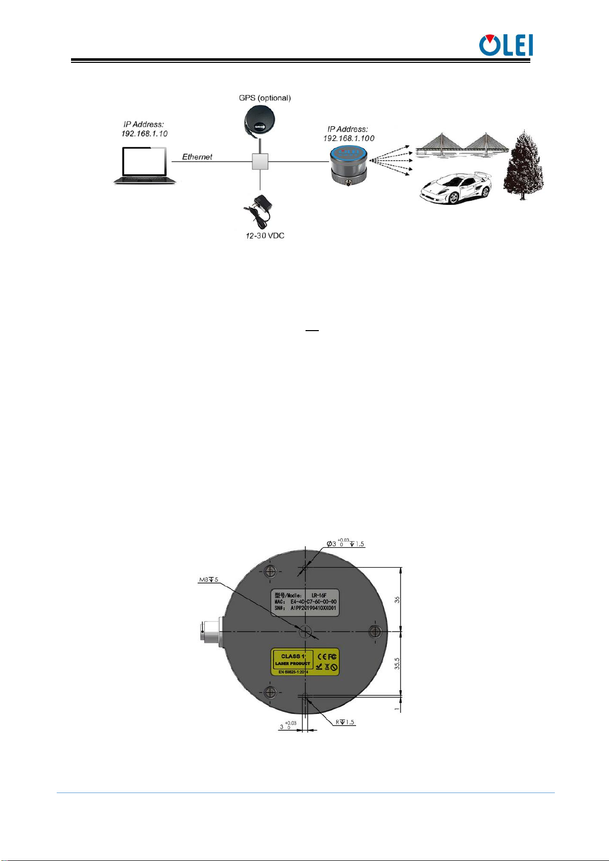
4. Installation and operation ........................................................................................................................................2
4.1. Mechanical interface............................................................................................................................................2
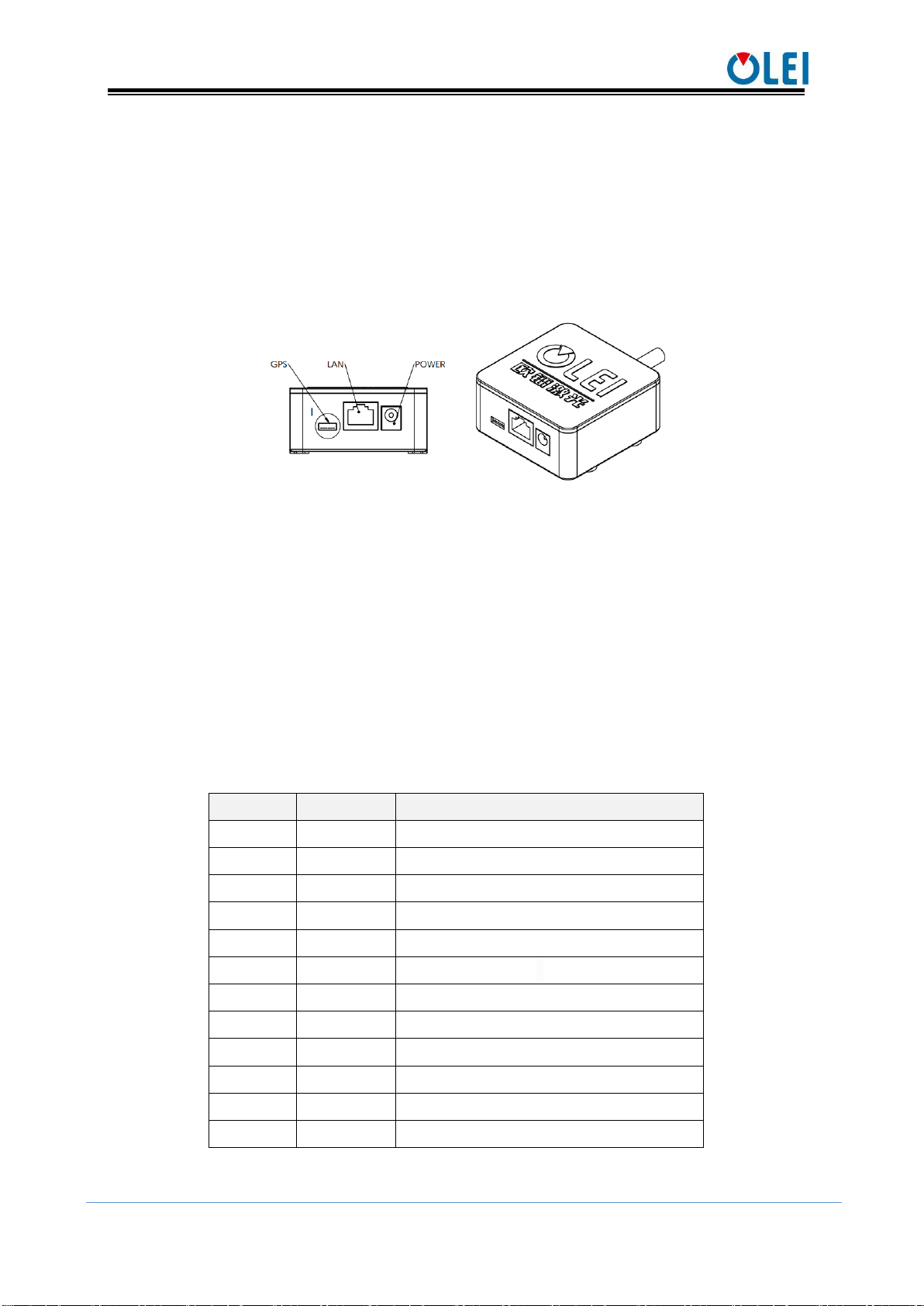
4.2. Electrical interface................................................................................................................................................3
4.2.1. Definition of aviation plugin .........................................................................................................................3
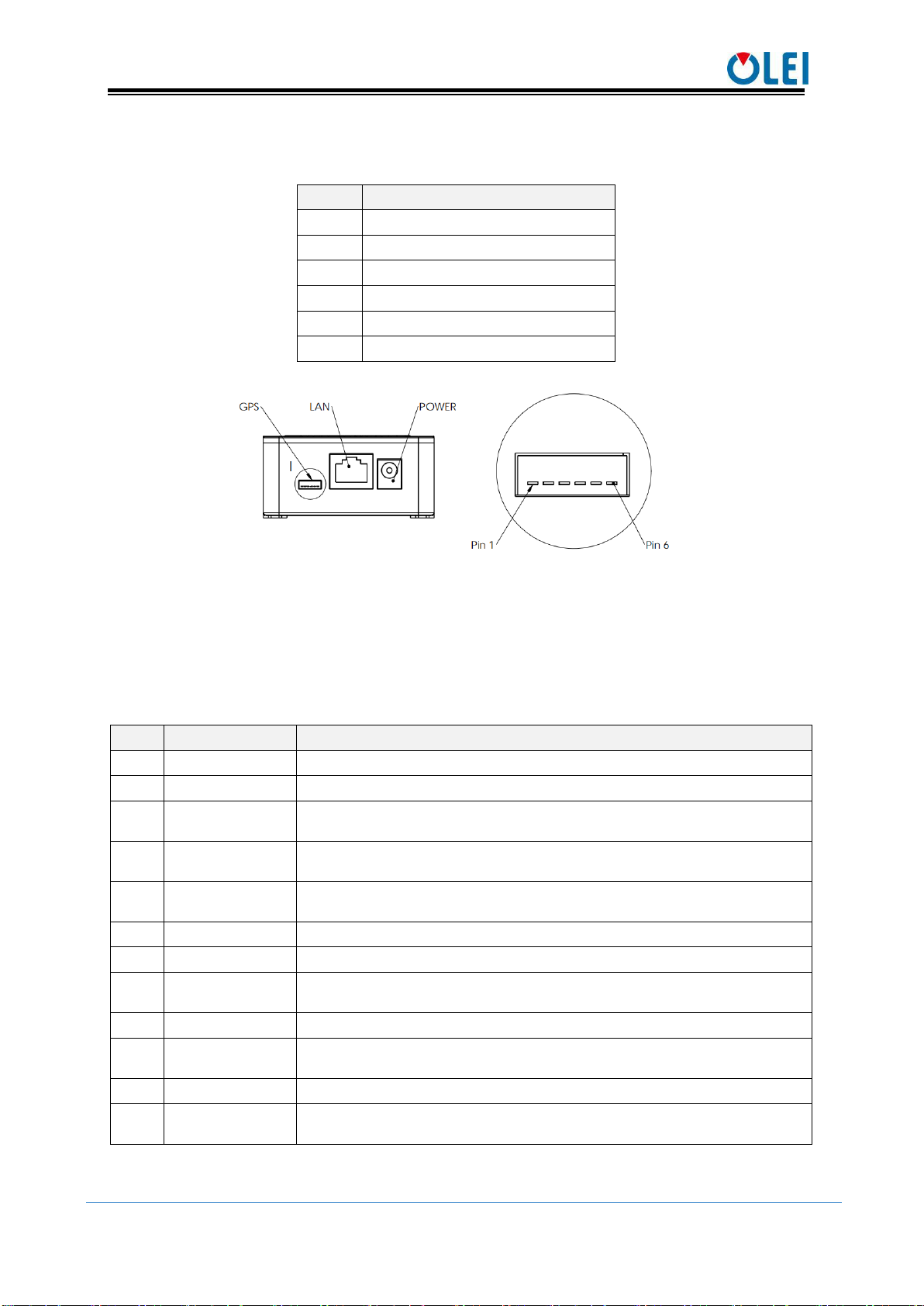
4.2.2. Definition of GPS ............................................................................................................................................4
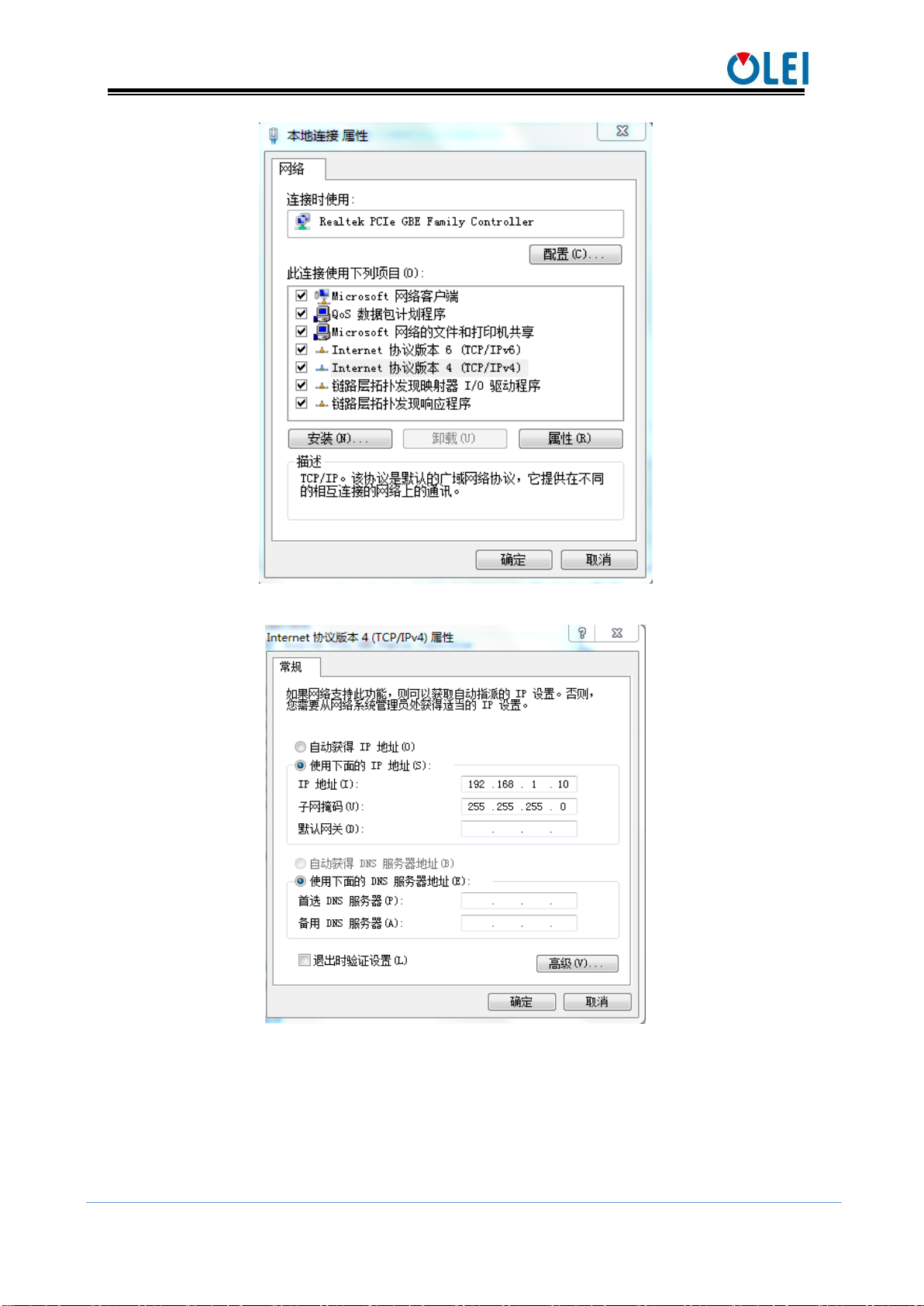
4.3. Communication interface....................................................................................................................................5
5. Serial port and PPS ...................................................................................................................................................6
6. Definition of vertical angle .....................................................................................................................................7
7. Format of data package............................................................................................................................................8
7.1. Communication protocol-data package...........................................................................................................8
7.1.1. Overview............................................................................................................................................................8
7.1.2. Header File ........................................................................................................................................................9
7.1.3. Time stamp ..................................................................................................................................................... 10
7.1.4. Factory mark .................................................................................................................................................. 10
7.2. Communication protocol-information package.......................................................................................... 10
7.2.1. Overview......................................................................................................................................................... 10
7.2.2. Definition of header...................................................................................................................................... 11
7.2.3. Definition of Lidar Info ............................................................................................................................... 11
7.3. Setup the protocol.............................................................................................................................................. 12
8. Numerical calculation ........................................................................................................................................... 13
8.1. Coordinate conversion...................................................................................................................................... 13
8.2. Azimuth ............................................................................................................................................................... 14
8.3. Azimuth interpolation....................................................................................................................................... 14
8.4. Distance ............................................................................................................................................................... 15
8.5. Time stamp.......................................................................................................................................................... 15
8.6. Emission time..................................................................................................................................................... 15
9. Parameter configuration of upper computer software ................................................................................... 16
9.1. Display software ................................................................................................................................................ 16
9.2. Configuration software..................................................................................................................................... 17
9.3. ROS driver package .......................................................................................................................................... 18
10. Troubleshooting ................................................................................................................................................. 18
Appendix A: Data Package ........................................................................................................................................... 19
Appendix B: Mechanical Dimensions........................................................................................................................ 22
Appendix C: Timetable .................................................................................................................................................. 23
Appendix D: GPS code analysis .................................................................................................................................. 24
Appendix E: analysis of 3D lidar coordinate code .................................................................................................. 24
Appendix F: analysis of interpolation code............................................................................................................... 25
Appendix G:ROS............................................................................................................................................................. 26
G.1 Install software........................................................................................................................................................ 26
G.2 Construction.............................................................................................................................................................. 26
G.3 Operation................................................................................................................................................................... 26
G.4 Real-time display..................................................................................................................................................... 27
Appendix H: Optical Avoidance Zone........................................................................................................................ 27

User Manual LR-16F
OMEN-16F-202012
1
1. Document description
To ensure the normal operation of the product and avoid damage to the equipment, please
do not disassemble the sensor.
Read the instructions: Please read through all safety and operating instructions carefully
before using this product;
Properly keep the instructions: Please keep all the safety and operating instructions
properly for future reference;
Pay attention to warnings: please pay attention to all warnings on the product and in the
user manual;
Follow the instructions: Please follow all operating instructions;
Maintenance instructions: please do not attempt to repair the product by yourself except
for following the troubleshooting instructions in the operation manual, and contact the
OLEI laser technicians for help in time.
Any equipment damage caused by violation of the above safety regulations is not covered
by the warranty.
2. Safety Instruction
Pay attention to laser radiation
This product contains invisible Class 1 laser;
Do not dissemble the cover of the device without authorization. Removing the cover will
not cause the laser to turn off;
The laser is not guaranteed to be still Class 1 after the cover is removed.
Pay attention to electrical safety
Disconnect the power supply when connecting or removing electrical cables,
The power supply connected to the equipment must meet the requirements of the
operating instructions;
When using the equipment, connect the reference potential terminal correctly to avoid
personal injury caused by equipotential current
3. Working Principle
With 16 laser emitting components rotating rapidly, LR-16F emits high-frequency laser
beams to continuously scan the external environment; the ranging algorithm provides three-
dimensional point cloud data and object reflectivity, allowing the machine to see the
surrounding environment, and providing guarantee for positioning, navigation, obstacle
avoidance, etc.

User Manual LR-16F
OMEN-16F-202012
2
Figure 1 LR-16F lidar operation schematic diagram
The distance information between the object and the lidar is obtained based on the TOF
(Time of Flight) principle, the flight speed and time of the laser beam. The calculation method
is as follows:
D—Detection range
T—Flight time
C—Speed of light
4. Installation and operation
4.1. Mechanical interface
LR-16F lidar can be installed at the bottom.
There is one M8 screw hole (hole depth is 5mm) at the bottom of the main body for
installation.
Figure 2 Installation interface of LR-16F

User Manual LR-16F
OMEN-16F-202012
3
4.2. Electrical interface
LR-16F component includes one Lidar main body, one junction box, one power adapter
and one network cable.
Operating voltage scope of LR-16F is 12~30VDC. The input end of the power adapter is
connected to 220VAC; the voltage at the power supply output end is converted to 12VDC by
the power adapter, and is connected to the junction box.
Figure 3 Electrical interface of LR-16F
4.2.1.Definition of aviation plugin
A cable containing an aviation plugin from the junction box, directly connects to the main
body of lidar. The connection can only be successful when the red dots on the male and female
plugs of the aviation plugin are aligned.
The aviation plug has a total of 12 PIN, among which PIN9 and PIN10 have two ground
wires in parallel, and PIN11 and PIN12 have two power wires in parallel. Actually, 12 cables
are connected to the junction box. The detailed definition of each PIN is shown in the table
below.
Definition of PIN of aviation plugin is shown in the following table:
Line order
color
function
1
orange
TXD-(send via network interface)
2
orange white
TXD+(send via network interface)
3
green
RXD-(receiving via network interface)
4
green white
RXD+(receiving via network interface)
5
grey
GPS-PPS(GPS sync pulse)
6
blue
GPS-RXD(GPS serial port receiving)
7
pink
reserved
8
yellow
reserved
9
brown
GND(grounding)
10
black
GND(grounding)
11
red
Vin(12~30V DC)
12
purple
Vin(12~30V DC)
Table 1 Definition of power supply and I/O interface

User Manual LR-16F
OMEN-16F-202012
4
4.2.2. Definition of GPS
GPS definition is shown in Table 2
No.
definition
1
PPS
2
5V
3
GND
4
RXD
5
GND
6
TXD
Table 2 Definition of GPS interface
Figure 4 Definition of GPS
5V is the output voltage, used for GPS power supplying; PPS uses 3.3V TTL level; RXD,
TXD uses 232 level.
GPS analysis:
$GPRMC,061124,A,3148.5621,N,12342.2488,W,163.4,132.8,191018,120.2,W,A*70
<1> <2> <3> <4> <5> <6><7> <8> <9> <10> <11><12>
No.
Value
Definition
1
061124
<1> UTC time in hhmmss (hour, minute and second) format
2
A
<2> Positioning status, A=effective positioning, V=invalid positioning
3
3148.5621
<3> Latitude ddmm.mmmm (degree and minute) format (the front 0 will
also be transmitted)
4
N
<4> Latitude Hemisphere N (Northern Hemisphere) or S (Southern
Hemisphere)
5
12342.2488
<5> Longitude dddmm.mmmm (degree and minute) format (the front 0
will also be transmitted)
6
W
<6> Longitude hemisphere E (east longitude) or W (west longitude)
7
163.4
<7> Ground rate (000.0~999.9 knots, the front 0 will also be transmitted)
8
132.8
<8> Ground heading (000.0~359.9 degrees, with true north as the
reference datum, the front 0 will also be transmitted)
9
191018
<9> UTC date in ddmmyy (day, month, year) format
10
120.2
<10> Magnetic declination (000.0~180.0 degrees, the front 0 will also
be transmitted)
11
W
<11> Magnetic declination direction, E (east) or W (west)
12
A*70
<12> Mode indicator (only NMEA0183 version 3.00 display,
A=autonomous positioning, D=differential, E=estimate, N=invalid data )
Table 3 Description of GPS analysis
For program analysis, please check “Appendix D: GPS code analysis” for reference.

User Manual LR-16F
OMEN-16F-202012
5
4.3. Communication interface
The LR-16F is connected to the computer by a standard Ethernet RJ-45 interface. The
computer IP address should be set up before communication. The lidar and computer IP must
be set in the same subnet without any conflict. The output package are mainly divided into
data package and information package, the port number of the data package is 2368, and the
port number of the information package is 9866.
The IP address settings on the computer is as follows:
Computer IP:192.168.1.10
Computer subnet mask: 255.255.255.0
The default factory settings of Lidar are as follows:
Lidar IP:192.168.1.100
Lidar subnet mask:255.255.255.0
The specific setting process on the computer is as follows:
Figure 5 Step 1 of computer IP setting

User Manual LR-16F
OMEN-16F-202012
6
Figure 6 Step 2 of computer IP setting
Figure 7 Step 3 of computer IP setting
5. Serial port and PPS
The serial port and PPS are mainly used when connecting to GNSS equipment. In order
to synchronize the lidar clock with GNSS, standard time signal provided by the GNSS receiver
should be input into LR-16F, including PPS signal and serial GPRMC data.

User Manual LR-16F
OMEN-16F-202012
7
The PPS signal should be a TTL level signal, the signal pulse length is 20ms~200ms, and
the GPRMC data must be completed within 500ms of the rising edge of the synchronous pulse.
Figure 8 PPS synchronous sequence
The baud rate of the serial port has the following options: 4800, 9600, 115200bps, 8bit
data bit, no parity bit, stop bit 1.
6. Definition of vertical angle
The vertical angle is defined as following:
Laser ID
Vertical Angle
0
-15°
1
1°
2
-13°
3
3°
4
-11°
5
5°
6
-9°
7
7°
8
-7°
9
9°
10
-5°
11
11°
12
-3°
13
13°
14
-1°
15
15°

User Manual LR-16F
OMEN-16F-202012
8
Figure 9 Schematic diagram of vertical angle definition
7. Format of data package
LR-16F enables laser point cloud data transmission. Please refer to the following for the
analysis of lidar point cloud data.
The information transmission between the LR-16F and the computer follows the UDP
standard network protocol. The data package adopts the Little-endian format, with the low
byte in the front and the high byte in the back.
7.1. Communication protocol-data package
7.1.1. Overview
The specific information stored in the data package is the distance value, calibrated
reflectivity, azimuth angle, time stamp and factory mark returned by the laser. The factory
mark contains sensor model and return mode information.
The total length of the data package is 1248 bytes, including 42 bytes for the header file,
1200 bytes for the laser returned data, 4 bytes for the time stamp, and 2 bytes for the factory
mark. The basic structure is shown in the figure below.

User Manual LR-16F
OMEN-16F-202012
9
Figure 10 Format of point cloud information packet
The total length of the data frame is 1248 bytes, among which
Frame header: 42 bytes
Data block: 12×(2+2+96)=1200 bytes
Time stamp: 4 bytes.
Factory mark: 2 bytes
7.1.2. Header File
Offset
Length
Description
0
14
Ethernet II include
Destination MAC:(6 Byte)
Sourse MAC:(6 Byte)
Type: (2 Byte)
14
20
Internet Protocol include
Version & Header Length :(1 Byte)
Differentiated Services Field: (1 Byte)
Total Length:(2 Byte)
Identification: (2 Byte)
Flags: (1 Byte)
Fragment Offse: (1 Byte)
Time to Live: (1 Byte)
Protocol: (1 Byte)
Header Checksum: (2 Byte)
Destination IP: (4 Byte)
Sourse IP: (4 Byte)
34
8
User Datagram Protocol include
Sourse Port:(2 Byte)
Destination Port: (2 Byte)
Data Length:(2 Byte)
Checksum: (2 Byte)
Table 4 Header files

User Manual LR-16F
OMEN-16F-202012
10
The laser returned data consists of 12 data blocks. Each data block starts with a 2-byte
identifier 0xFFEE, followed by a 2-byte azimuth angle and a total of 32 data points. The laser
returned value of each channel contains a 2-byte distance value and a 1-byte calibration
reflectivity value.
Offset
Length
Description
0
2
Identifier, fixed value as 0xFFEE
2
2
Angle data
4
2
Ch0 distance data
6
1
Ch0 reflectance data
7
2
Ch1 distance data
9
1
Ch1 reflectance data
10
2
Ch2 distance data
12
1
Ch2 reflectance data
...
...
...
49
2
Ch15 distance data
51
1
Ch15 reflectance data
52
2
Ch0 distance data
54
1
Ch0 reflectance data
55
2
Ch1 distance data
57
1
Ch1 reflectance data
58
2
Ch2 distance data
60
1
Ch2 reflectance data
...
...
...
97
2
Ch15 distance data
99
1
Ch15 reflectance data
Table 5 Data block structure
7.1.3. Time stamp
7.1.4. Factory mark
Offset
Length
Description
0
2
Factory:(2 Byte)0x00,0x10
7.2. Communication protocol-information package
7.2.1. Overview
Header
Lidar Info
GPS Info
42 Bytes
768 Bytes
74 Bytes
Length of data package: 884 Bytes
Offset
Length
Description
0
4
time stamp[31:0]
[31:20] count of seconds
[19:0] count of milliseconds

User Manual LR-16F
OMEN-16F-202012
11
Note: The port number of the information package cannot be changed, the local and
target ports are both 9866
7.2.2. Definition of header
Offset
Length
Description
0
14
Ethernet II include
Destination MAC:(6 Byte)
Sourse MAC:(6 Byte)
Type: (2 Byte)
14
20
Internet Protocol include
Version & Header Length :(1 Byte)
Differentiated Services Field: (1 Byte)
Total Length:(2 Byte)
Identification: (2 Byte)
Flags: (1 Byte)
Fragment Offse: (1 Byte)
Time to Live: (1 Byte)
Protocol: (1 Byte)
Header Checksum: (2 Byte)
Destination IP: (4 Byte)
Sourse IP: (4 Byte)
34
8
User Datagram Protocol include
Sourse Port:(2 Byte)
Destination Port: (2 Byte)
Data Length:(2 Byte)
Checksum: (2 Byte)
Table 6 Definition of header
7.2.3. Definition of Lidar Info
offset
Length
Description
0
6
Factory code
6
12
Machine model
18
12
Serial number
30
4
Sourse IP
34
2
Sourse data Port
36
4
Destination IP
40
2
Destination data Port
42
6
Sourse MAC
48
2
Motor speed
50
1
[7] GPS connection flag, 0: connected, 1: not connected
[6] Upper circuit error flag 0: normal, 1: error
[5:0]Reserved

User Manual LR-16F
OMEN-16F-202012
12
offset
Length
Description
51
1
GPS enable & baud rate, 0x00: GPS power off
0x01: GPS power on, baud rate 4800
0x02: GPS power on, baud rate 9600
0x03: GPS power on, baud rate 115200
52
1
Reserved
53
1
Reserved
54
2
The temperature of the upper circuit board, the data should multiply by
0.0625℃
56
2
The temperature of the lower circuit board, the data should multiply by
0.0625℃
58
2
Reserved
60
32
CH0-CH15 channel static offset
92
4
Reserved
96
672
Reserved
768
74
GPS information
Table 7 Definition of LiDAR Info
7.3. Setup the protocol
Follow the UDP protocol, user setup protocol, upper computer sends 8 bytes
Name
address
data
number of bytes
2 bytes
6 bytes
address
Name
Byte meaning [31:0]
F000
IP
Local IP
[47:16]=local_ip,[15:0] =local_port
F001
Remote IP
[31:0]=remote_ip,[15:0]= remote_port
F002
Speed, GPS
enable,
baud rate
[47:32] =rom_speed_ctrl
[31:24]=GPS_en 0x00 = off
0x01 = enabled and the baud rate is 4800
0x02= enabled and the baud rate is 9600
0x03 = enabled and 115200 baud rate
[23:0]Reserved
Example:
Local ip and port F0 00 C0 A8 01 64 09 40 192.168.1.100 2368
Target ip and port F0 01 C0 A8 01 0A 09 40 192.168.1.10 2368
Rotating speed F0 02 02 58 00 00 00 00 speed 600
Restart the 3D radar each time the modification is completed.
Optional rotating speed: 300 or 600. optional baud rate:4800/9600/115200 .

User Manual LR-16F
OMEN-16F-202012
13
8. Numerical calculation
8.1. Coordinate conversion
The information in the LR-16F data package is the azimuth value and distance value
established in the polar coordinate system. It’s more convenient to construct three-
dimensional scene through the point cloud data by converting polar coordinate value to
Cartesian coordinate system.
The above values corresponding to each channel is shown in the following table:
Channel
number
Vertical
angle ω
Horizontal angle α
Horizontal
offset A
Vertical offset
B
CH0
-15°
α
21mm
5.06mm
CH1
1°
α+1*0.00108*H
21mm
-9.15mm
CH2
-13°
α+2*0.00108*H
21mm
5.06mm
CH3
3°
α+3*0.00108*H
21mm
-9.15mm
CH4
-11°
α+4*0.00108*H
21mm
5.06mm
CH5
5°
α+5*0.00108*H
21mm
-9.15mm
CH6
-9°
α+6*0.00108*H
21mm
5.06mm
CH7
7°
α+7*0.00108*H
21mm
-9.15mm
CH8
-7°
α+8*0.00108*H
-21mm
9.15mm
CH9
9°
α+9*0.00108*H
-21mm
-5.06mm
CH10
-5°
α+10*0.00108*H
-21mm
9.15mm
CH11
11°
α+11*0.00108*H
-21mm
-5.06mm
CH12
-3°
α+12*0.00108*H
-21mm
9.15mm
CH13
13°
α+13*0.00108*H
-21mm
-5.06mm
CH14
-1°
α+14*0.00108*H
-21mm
9.15mm
CH15
15°
α+15*0.00108*H
-21mm
-5.06mm
Table 8 Coordinate conversion
Note: Under normal accuracy, the horizontal angle α only needs to increase the parameters in
the table above.
The calculation formula for space coordinates is
BRZ
ARY
ARX
)sin(*
)(sin*)cos(*)cos(*
)cos(*)sin(*)(cos*
Definitions
The measured distance output by each channel of the radar is set as R. Note that the unit
of the radar input is 2mm, please convert to 1mm first
Rotating speed of radar is set as H (usually 10Hz)
The vertical angle of each channel of the radar is set as ω
The horizontal angle output by the radar is set as α

User Manual LR-16F
OMEN-16F-202012
14
The horizontal offset of each channel of the radar is set as A
The vertical offset of each channel of the radar is set as B
The spatial coordinate system of each channel of the radar is set as X, Y, Z
Figure 11 Coordinate transformation definition
For program analysis, see “Appendix E: 3D Lidar Coordinate Code Analysis” for reference.
8.2. Azimuth
Each data package records 12 azimuth values, which are located after the 0xFFEE flag
of each data block. The azimuth angles of the last 16 laser beams of each data block are
obtained through interpolation calculation. See the next section for specific methods.
The specific calculation method and steps of the azimuth angle are shown in the
following example:
1) Obtain the azimuth value: 0x21 & 0x63
2) Interchange of high byte and low byte: 0x63 & 0x21
3) Combine into an unsigned hexadecimal number: 0x6321
4) Converted to decimal number: 25377
5) Multiply by the minimum resolution: 0.01°
6) Result: 253.77°
The 0° of the azimuth is coaxial with the base of lidar main body,and in the opposite
direction.
8.3. Azimuth interpolation
LR-16F can directly obtain the azimuth angle of the first 16-line laser pulse sequence in
each data block through the data package, and then obtain the azimuth angle value of the
second 16-line laser pulse sequence through interpolation calculation.
Assuming that among the 24 laser sequences of 12 data blocks, the adjacent 3 sequence
numbers are N, N+1, and N+2, and the values of N and N+2 are known. The simplest and
most direct method is to calculate the azimuth value of N+1 through N and N+2 interpolation
(By default, the rotation speed is constant during the whole process). For the interpolation
procedure, see “Appendix F: Interpolation Code Analysis” for reference.

User Manual LR-16F
OMEN-16F-202012
15
8.4. Distance
Distance calculation method of LR-16F is similar to that of azimuth angle, as is shown
in the following example:
1)Obtain the distance value:0x11 & 0x21
2)Interchange of high byte and low byte:0x21 & 0x11
3)Combine into an unsigned hexadecimal number:0x2111
4)Convert to decimal number:8465
5)Multiply by the minimum resolution:2mm
6)result:16930mm
8.5. Time stamp
The calculation method of timestamp of LR-16F is shown in the following example:
1)Obtain time stamp data:0x43 & 0x32&0x21&0x10
2)Interchange of high byte and low byte:0x10&0x21&0x32&0x43
3)Combination
0X10
0X21
0X32
0X43
0
0
0
1
0
0
0
0
0
0
1
0
0
0
0
1
0
0
1
1
0
0
1
0
0
1
0
0
0
0
1
1
Second(uint16)
Microsecond(uint32)
Calculation of second
0
0
0
0
0
0
0
1
0
0
0
0
0
0
1
0
Second(uint16)
Convert from binary to decimal: 258 unit:s
0
0
0
0
0
0
0
0
0
0
0
0
0
0
0
1
0
0
1
1
0
0
1
0
0
1
0
0
0
0
1
1
Convert from binary to decimal: 78403 unit: us
4)Calculate seconds:258+78403/1000000=258.078403
8.6. Emission time
The laser emission time of each channel of LR-16F is 3us, and there is a waiting time of
3us after all 16-line lasers are emitted. The total time for each 16 channels of laser to complete
a round is 51us. Therefore, the laser beam after the first channel has a corresponding time
offset.
To calculate emission time of the laser beam of any channel in any data block in the
data package, the 24 laser sequences should be numbered as M(M is 0~23) according to the
sequence of data blocks, the 16 laser channels for each laser sequence are numbered as N, and
the laser emission time Tshift of each channel is: (refer to Appendix C)
)*3()*51(
shift NMT

User Manual LR-16F
OMEN-16F-202012
16
Figure 12 Laser emission time
In fact, the final emission time should add a time stamp. The time stamp records the
emission time of the first channel of the first data block in each data package. The true
valueTreal is:
9. Parameter configuration of upper computer software
Upper computer software is divided into display software configuration software and
ROS driver package.
9.1. Display software
The upper computer display software interface is shown in the figure below. Please refer
to the Olamview 2.0 software manual for detailed usage.
Figure 13 Example of upper computer software interface

User Manual LR-16F
OMEN-16F-202012
17
The web page setting interface and the upper computer software interface may change
due to continuous updated products, and the actual content shall prevail.
9.2. Configuration software
The configuration software 3D Lidar config Ver1.0.2 is mainly used to modify and
configure the basic parameters of 16-line lidar. The software interface is as shown below
Lidar Ip: Lidar IP;
Lidar Port: Lidar Port;
Remote Ip: host IP;
Remote Port: host port;
Motor RPM: Lidar rotating speed, optional 300/600;
GPS Enable: GPS port, select Disable if there’s no GPS.
Instructions:
1.Connect the lidar according to the correct method to make the communication normal;
2.Click Connect. After the data on the left side of the figure below is normal, click Modify to
modify the corresponding parameters as needed;
3.Restart lidar to make parameters effective.
4.When in the Connect state, in the right-click menu of the Lidar Info area, you can choose to
reset the Lidar IP configuration to factory defaults.

User Manual LR-16F
OMEN-16F-202012
18
9.3. ROS driver package
In order to make it easier for customers to use ROS platform in the Linux environment,
we developed the ROS driver package Olam3D_C.zip. Refer to Appendix G for specific
building and compiling steps Please contact technical staff from OlEI if necessary.
Note: If a red error message appears during the process of driver installation, it maybe
caused by limited authority under Ubuntu. Please run the instruction "chmod -R 777
src" to obtain executable permissions.
10.Troubleshooting
Problem
Method
Lidar fails to scan
Verify whether the power supply is properly connected
Verify whether the power voltage meets 12~30VDC
Verify whether the motor rotates normally
No data on Lidar scan
Verify whether the network connection is normal
Try to use third-party data scraping software to obtain data
Verify the settings of the data receiving computer, such as IP, etc.
Verify whether there is security software blocking data transmission
Table 9 Troubleshooting
Table of contents
Other OLEI Accessories manuals