NAD 7140 User manual

NAD

1. AM Rod Antenna
2. Antenna Terminals
3. Coaxial Antenna Input
4. Phono Input
5. Phono Ground
6. MM/MC Phono Selector
7. CD Input
8. Aux Input
9. Tape Rec/Play
10. Preamp Out, Main In
11. Soft Clipping
12. Speaker Impedance
13. Bridging
14. AC Line Cord
15. AC Convenience Outlets (Not in U.K. model)
16. Speakers A
17. Speakers B
1217 16 15
R
s;:·~~;I~>~~>
NAD ELECTRONICS, INC.
BOS1 (lN/l,ON!XJN/TOK Y{)
456789310 11 12 13 14
CAUTION: TO REDUCE
THE RISK OF ELECTRIC
SHOCK. DO NOT REMOVE
COVER (OR BACK)
NO USER-SERVICEABLE
PARTS INSIDE. REFER
SERVICING TO QUALIFIED
SERVICE PERSONNEL
1. Power
2. Phones
3. Speaker Selector
4. Bass
5. Treble
6. Bass Equalization
7. InfrasonicFilter Defeat
8. Mono
9. DynSep Defeat
10. TapeMonitor
11. InputSelector
12. Low Level
13. LoudnessCompensation
14. Volume/Balance
15. TuningSearch
16. Up/DownTuning
17. AM/FM
18. Memory Enter
19. Station Pre-Sets
20. FMStereo Indicator
21. Soft Clipping Indicator
22. TuningDisplay
122 21 20 19 18 17 16
CD PH()NO rUNER AU);
3 4 ::. ENILR MJ,f':M
c::Jc::::::::Jc::::::::Jc::::::::Jc::::::::J
rAPE
~)NI100
~III.
FA1
AM
IIIIIUllllm
BASS INFRA DYNSf:>'
EO DEFf;:AT MONO DEFEA.T
!"BURr:BASS
Stereo Recei"cr 7140
SPEAKER~~
B OfF A+B
PHONES
2345678 9 10 11 12 13 14 15
2

REAR PANEL CONNECTIONS
2. A more elaborate rabbit-ears indoor TV antenna with
f
1. AM ROD ANTENNA. The ferrite rod antenna provides
a tuning switch. This type of antenna does NOT have greater
sensitivity than the simpler rabbit-ears unit, so if your problem
effective reception of local AM radio broadcasts. The rod is is that the signals you want to receive are weak (as shown
mounted on a pivot. For best reception, swing it away from the on the signal-strength indicator), then an outdoor antenna is
metal chassis of the receiver. the only effective solution. But in cities and in large buildings
2. ANTENNA TERMINALS. If you are using an external where signals are strong but are contaminated by reflected
FM antenna with a coaxial cable, it should be plugged into the "multi path" signals that interfere with good reception, the
75-ohm coaxial socket (discussed below). Other types of an- tuning switch on an elaborate indoor antenna may improve
tenna wires, including the twin-lead FM antenna supplied with reception by reducing the interference.
the receiver, may be attached to the four antenna terminals. 3. An electrically tuned indoor antenna, such as the
Remove any connector that is fitted on the antenna wire, Technics Wing or B.I.C. Beam Box. Again, such antennas
'I strip off 1 cm of insulation from each conductor, and in each
usually do not provide any advantage over the simplest type
conductor twist together the exposed wire strands. Lift up the of "rabbit-ears" unit for receiving weak signals. But where a
plastic tab below the terminal, insert the bared wire into the strong signal is contaminated by interference, the antenna's
small hole in the terminal, and press the tab firmly down. aiming and tuning controls can reject the interference and
The terminal will grasp the wire and hold it in place. yield cleaner reception.
AM. Since the receiver is equipped with a ferrite rod 4. An outdoor antenna. Even the finest indoor antenna,
antenna, no external antenna will be needed for satisfactory no matter how elaborate, cannot fully exploit the capabilities
reception of most local broadcasting stations. But if you wish of a good FM tuner. For the lowest noise, minimum distortion,
to improve reception of distant AM stations, attach a long- and largest choice of well-received broadcasts, an outdoor
wire outdoor antenna to the AM terminal. As its name implies, antenna is the best complement to a fine tuner.
a "long-wire" antenna is a simple, straight wire whose A roof-mounted antenna has three fundamental advan-
length may be anything from a few feet up to about 100 feet tages. First, its large size yields better sensitivity (pulling in
(30 meters), mounted parallel to the earth and as high as a stronger signal from the desired station) and a narrower
is convenient. directional pattern for more effective rejection of multipath
In some cases the effectiveness of a long-wire antenna reflections arriving from other directions. Second, its loca-
i
will be improved by connecting a second wire from the Ground
tion on a roof or tall mast places it above many sources of
(G) terminal to a true earth-ground, i.e., a copper-plated rod interference-passing cars and buses, other buildings, etc.
driven several feet into the earth. A substitute electrical Third, the strength of received FM signals is directly propor-
ground may also prove effective: a cold-water pipe, a steam tional to the height of the antenna above the ground.
radiator, or the third hole of a modern electrical wall socket. If you already have an outdoor television antenna, using
FM. Some form of antenna must be connected to the a splitter to extract FM signals from it may produce excellent
tuner for effective reception of stereo FM broadcasts. results. However, many TV antennas are deliberately de-
A ribbon-wire "folded dipole" antenna is supplied with the signed to be relatively weak at FM frequencies in order to
receiver to get you started. When you stretch out the ribbon- minimize potential interference with TV signals at nearby
wire antenna you will note that it is in the form of a "T". The frequencies (Channel 6 in the U.S.). You may be able to use
"crossbar" portion of the T should be stretched out horizon- a splitter to extract FM signals from an apartment building's
tally and tacked in place-on a wall, on the back of a cabinet, master TV antenna system, but usually this yields poor results
or on the floor. The "vertical" section of the T goes to the because many master antenna systems have "traps" to stop
I
receiver's 3000 antenna terminals. FM signals.
I
!FM·ANTENNAS. In view of the exceptional sensitivity of
The best choice is a directional FM-only antenna,
this receiver, you may find that the ribbon-wire dipole antenna mounted as high above ground as is practical, and separated
is all you need for reception of strong local stations. But it is by at least two meters (7 feet) from other antennas, vertically
not very efficient at rejecting "multi path" and other forms of and horizontally. Brand names of good FM antennas in the
FM interference, and it cannot easily be rotated to optimize its U.S. include Jerrold, Finco, Wineguard, Antennacraft, and
pickup pattern for best reception of stations in different direc- Archer (Radio Shack). A shielded lead-in cable will be desir-
tions. Therefore, in most cases you should use a better able in most locations, both to minimize interference and to
antenna. The recommended options, in order of increasing preserve strong signals during years of weathering. The
cost, are as follows: cable may be either 75-ohm coaxial or a shielded 300-ohm
1.A basic "rabbit-ears" indoor TV antenna without auxil- type. If desired stations are located in different directions
iary coils or tuning switches. Electrically, such an antenna is
(more than 90 degrees apart), a rotor will also be needed in
just another dipole (similar to the ribbon-wire antenna) with its
order to aim the antenna.
tuned elements made of solid metal, but with the advantage 3. 7Sfl COAXIAL ANTENNA INPUT. This socket provides
that it can be rotated. Stretch out each of its two arms to a length of 30 inches (75 em), and orient them horizontally or at a convenient means of connecting a 75-ohm coaxial cable
a shallow angle upward (less than 45 degrees). The ribbon from your antenna or from a community cable system.
wire emerging from the antenna's base should be connected If you are using a coaxial antenna cable to which a
I
to the tuner's two 3000 terminals in place of the ribbon-
connector has already been fitted, simply plug it into the 750
wire antenna supplied with the tuner. Now, for each station socket, and disconnect any other wires from the 3000 an-
in turn, after you tune the station you can rotate the antenna tenna terminals. If the cable has no connector, you may attach
,
for best reception. its center conductor to one of the 3000 antenna terminals,
./Ii:;.1i9~0109 ""h w,"","wh••', wlihlo'0 "01',,,,,,
~ "d~,floo pololwllhlo'0 "oil",,,, "',ogl, I,101'0'00
triangle, is intended to alert the user of the presence of to alert the user of the presence of important operating and
uninsulated "dangerous voltage" within the product's enclo- maintenance (servicing) instructions in the literature
sure; that may be of sufficient magnitude to constitute a accompanying the appliance.
I
risk of electric shock to persons. I
I
3
j

I
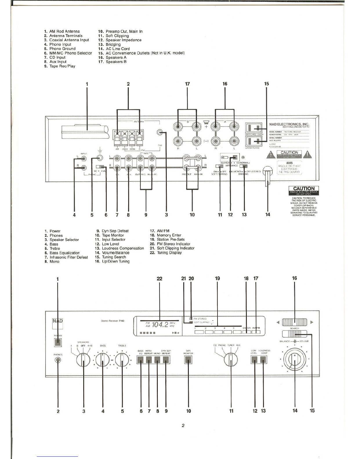
and connect its cable shield to the Ground (G) terminal. But
the better approach is to install a connector on the coaxial
cable, and plug it into the 750 socket.
The antenna terminals are connected to the FM tuner
circuit through an internal "balun" transformer that allows the
use of either a "balanced" 300-ohm twin-lead antenna cable
(connected to the two 3000 terminals) or an "unbalanced"
75-ohm coaxial cable (with its center conductor connected
to one of the 3000 terminals and the cable shield connected
to the Ground (G) terminal. However, a slight signal loss
can occur in such a transformer. The 750 coaxial socket is
connected directly to the FM tuner circuit, bypassing the
transformer, and so this is the preferred input when the best
possible input sensitivity is required.
4. PHONO INPUT. Plug the signal cables from your
turntable into these jacks. If the cables or plugs are color-
coded, refer to your turntable's instruction manual to learn
which cable or plug is for the Left channel (upper jack) and
which for the Right (lower jack). Be careful to insert each plug
fully into the socket so that the plug's metal skirt fits tightly
over the exterior of the socket. If necessary, crimp the plug's
metal skirt slightly so as to obtain a tight fit with the socket.
5. PHONO GROUND. If your turntable is equipped
with a grounding wire (usually a green wire terminating in
a U-shaped spade lug), connect it to this terminal. Turn the
thumb-nut counter-clockwise, place the spade lug under the
nut, and tighten the thumb-nut clockwise to secure the lug.
If the grounding wire has no terminal lug, strip off a half-inch
(1 to 2 em) of insulation to expose the bare wire, twist the wire
strands tightly together, insert the wire through the small hole
in the shaft of the Ground terminal, and tighten the thumb-nut
to fasten the wire in place.
If you encounter a persistent low-level hum or buzz in
the sound, connect a wire from the Ground terminal to a true
earth-ground, i.e., a copper-plated rod driven several feet into
the earth. A substitute electrical ground may also prove effec-
tive: a cold-water pipe, a steam radiator, or the third hole of a
modern electrical wall socket.
6. MM/MC PHONO SELECTOR. This switch sets the in-
put sensitivity and gain of the phono preamplifier circuit. Set it
according to the output level of your phono pickup cartridge.
Set the switch at MM for cartridges of the moving magnet,
induced magnet, moving flux, and moving iron (variable flux)
types, and for "high output" moving-coil pickups, i.e., those
with a rated output of 1.0 mV or greater. If your cartridge is a
low-output moving-coil pickup (with a rated output less than
1.0 mV), set the switch at MC.
Here is another way to determine the correct setting of
the MM/MC switch. Begin by setting it to MM. After you have
completed the installation and wiring of the receiver, playa
record. You should obtain a satisfyingly loud volume level at
VOLUME control settings between 9 o'clock and 3 o'clock. If
you have to turn up the VOLUME control beyond 3 o'clock to
get adequately loud sound, turn the volume back down and
re-set the MM/MC switch to MC.
7. CD INPUT. Connect the audio signal cables from a
digital Compact Disc player to these jacks. The input signal
will be fed to the VOLUME control before reaching any active
circuitry, so the amplifier's circuits cannot be overloaded by
high-level signals from the digital player.
If you don't have a CD player, any other line-level signal
source (such as a spare tape deck) may be connected to the
CD input.
8. AUX INPUT. These auxiliary jacks are for any "line
level" signal source, such as a spare tape deck, the audio line
output from a videocassette or videodisc player, or a television
sound tuner. As with all of the other input/output jacks on this
amplifier, the upper jack in each pair is for the Left channel
and the lower jack is for the Right channel.
4
9. TAPE REC/PLAY. The tape connections may be used
with recorders of all types: cassette, micro-cassette, open-
reel, digital, etc. To make recordings, connect a stereo patch
cord from the amplifier's TAPE OUT (RECording) jacks to the
recorder's LINE INPUT jacks (not to its microphone inputs).
To play back tapes, connect a stereo patch cord from the
recorder's LINE OUTPUT jacks to the amplifier's TAPE IN
(PLAYback) input jacks.
The TAPE REC/PLAY jacks may be used for connecting a
signal-processing accessory instead of a tape recorder. Exam-
ples of such accessories include a dynamic range processor, a
dynamic noise filter, a DBX disc decoder, or any other device
whose operation depends on the setting of a signal threshold.
Connect a patch cord from the TAPE OUT (REC) jacks to the
processor's inputs, and another patch cord from the proces-
sor's outputs to the TAPE IN (PLAY) jacks.
Other signal processing accessories, such as a graphic
equalizer or the special equalizer supplied with some loud-
speakers, may be connected either to the TAPE jacks or at the
Preamp Out jacks. The choice is a matter of convenience.
10. PREAMP OUT, MAIN IN. Each channel of the ampli-
fier is composed of two independent sections or stages: the
control preamplifier (including the phono preamp and most
front-panel controls), and the power amplifier (which provides
the power to drive loudspeakers). In normal operation the
preamp and power amp are connected together via factory-
installed U-shaped metal jumpers that bridge the PRE-OUT
and MAIN-IN jacks. Check to be sure that the jumpers are fully
inserted into the jacks and that nothing is touching them.
By removing the metal jumpers (after first switching OFF
the POWER), you can connect various signal-processing
accessories in the path between preamp and power amp: an
equalizer, a time-delay ambience reproducer, a stereo image
enhancer, an electronic crossover, etc. To use a signal proces-
sor, connect a stereo patch cord from the PRE-OUT jacks
to the processor's line-level input jacks, and a second patch
cord from the processor's output jacks to the amplifier's
MAIN-IN jacks.
NOTE: any signal processor whose operation depends
on the setting of a threshold, such as a dynamic noise filter,
should be connected to the TAPE REC/PLAY jacks-where
the signals are unaffected by the amplifier's volume and tone
controls-rather than the PREAMP OUT jacks.
If you remove the metal jumpers, save them in case you
may want to disconnect the signal processor and return to
normal operation at a later time. If the jumpers should be lost,
a conventional stereo patch cord can be used to connect
PRE-OUT to MAIN-IN in each channel.
This amplifier can be used as the heart of an elaborate
audiophile sound system. The preamp output is capable of
driving several power amplifiers simultaneously, or of driving
the long signal cables required to connect to power amps
which are located near the speakers (or to "powered" active
loudspeakers with built-in power amplifiers).
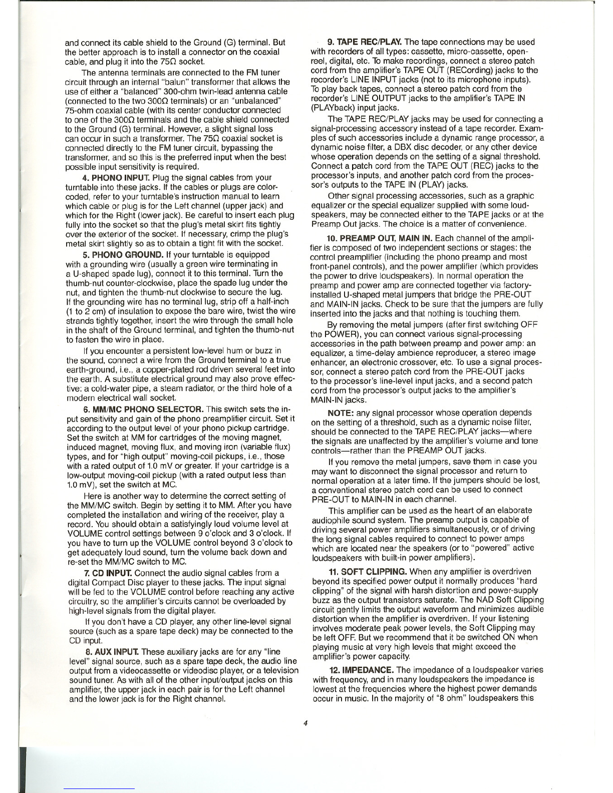
11. SOFT CLIPPING. When any amplifier is overdriven
beyond its specified power output it normally produces "hard
clipping" of the signal with harsh distortion and power-supply
buzz as the output transistors saturate. The NAD Soft Clipping
circuit gently limits the output waveform and minimizes audible
distortion when the amplifier is overdriven. If your listening
involves moderate peak power levels, the Soft Clipping may
be left OFF. But we recommend that it be switched ON when
playing music at very high levels that might exceed the
amplifier's power capacity.
12. IMPEDANCE. The impedance of a loudspeaker varies
with frequency, and in many loudspeakers the impedance is
lowest at the frequencies where the highest power demands
occur in music. In the majority of "8 ohm" loudspeakers this

minimum impedance is from 4 to 6 ohms, and in "4 ohm"
speakers the minimum is typically 3 ohms. If you connect two
sets of speakers to the amplifier, their combined impedance is
approximately half the impedance of either. For these reasons,
all NAD amplifiers and receivers are designed to produce
maximum power output into impedances of 2 to 6 ohms.
If you are not sure of the true impedance of your speak-
ers, or if you are connecting two pairs of speakers, leave the
impedance switch in the 40 (NORMAL) position.
If you are using a single pair of loudspeakers whose
impedance is 8 ohms or higher, you can re-set this switch to
80 (HIGH), re-optimising the amplifier for maximum power
delivery at this higher impedance. First, switch OFF the
POWER. Note that the Impedance switch is held in place by
a plastic bracket which is fastened by a screw. Use a small
screwdriver to loosen the bracket screw, turning it about a
half-turn counter-clockwise, and slide the switch to the left.
(The bracket will move with the switch.) Re-tighten the screw
to secure the switch to the 80 (HIGH) position.
If the Impedance switch is set to 80 (HIGH) with speakers
whose true impedance is lower than 6 ohms, or with two pairs
of speakers connected, the amplifier may overheat and shut
down when operated at continuously high output levels. Nor-
mally the amplifier will resume normal operation after it cools
down. But a severe, sustained overload could cause internal
fuses to blow in order to protect the amplifier; in that case you
should return the amplifier to your dealer for service.
13. BRIDGING. This switch "bridges" the two power
amplifier channels to form a monophonic amplifier with more
than double the output power. To convert to bridged operation,
the following procedure should be followed.
1. Switch OFF the POWER.
2. Be sure that the IMPEDANCE switch is set to 40
(NORMAL). If it is at 80 (HIGH), re-set it to 40 (NORMAL)
and tighten the bracket to prevent the Impedance switch from
being moved accidentally.
3. Disconnect the metal jumper or signal cable from the
Left-channel Main input to the power amplifier section of the
7140. Leave the Right-channel jumper in place from PRE-OUT
to MAIN-IN. In the bridged mode the amplifier is driven only
through its Right-channel Main input. (If you need stereo-
phonic reproduction, the Left-channel PREAMP OUT signal
can be used to drive a second, separate power amplifier.)
When two bridged amplifiers are used for stereo, this 7140
receiver normally becomes the "Right channel" amplifier, and
the other amplifier is connected to the "Left channel" speaker.
If another NAD amplifier in bridged mode is used for the
second stereophonic channel, it too will be driven through
its "Right" Main input, even though it is connected to the
Left speaker.
4. Disconnect any speaker wires from both the SPEAK-
ERS A and SPEAKERS B terminals. From the speaker which
is to be driven by this bridged 7140, connect its "positive" lead
to the R+ terminal and its "negative" lead to the L+ terminal
(i.e., to the two red terminals in the "P\' group. DO NOT
connect any wires to the black terminals (R- and L-).
If you want to drive two speakers in parallel, connect the
second speaker's leads to the red (R+ and L+) terminals in
the "B" group. Do not connect any wires to the black (R- and
L-) terminals.
NOTE: In the bridged mode the loudspeaker's impedance
is effectively halved as "seen" by the amplifier. An 8-ohm load
looks like 4 ohms, a 4-ohm load looks like 2 ohms, and a pair
of 4-ohm speakers operated in parallel will look like a 1-ohm
load. Driving a pair of such speakers to high levels will cause
the amplifier to overheat and shut down, or may cause internal
fuses to blow in order to protect the amplifier. For best results
the bridging mode should be used with only a single 4-ohm or
8-ohm speaker in each channel.
5
CAUTION: In the bridged mode the speaker wires
must be "floating" with respect to the circuit ground. Do
NOT connect the speaker wires to anything which shares
a common ground between stereo channels (such as a
speaker switch or an adapter for electrostatic headphones),
nor to anything which shares a common ground with the
amplifier's inputs (such as a switching comparator or a
distortion analyzer).
5. After the preceding conditions have been satisfied,
re-set the Bridging switch. It is held in place by a plastic
bracket and a screw in a slot. Use a small screwdriver to
loosen the bracket screw, turning it about a half-turn counter-
clockwise; then slide the switch to the left, to ON (MONO).
The bracket will move with the switch. Re-tighten the screw
to secure the switch in its new position. Finally, turn the am-
plifier's power on.
6. To return the amplifier to normal stereo operation at a
later date, first turn off the power. Loosen the bracket screw,
re-set the Bridging switch to OFF (STEREO), and tighten the
bracket screw to prevent the switch from being moved acci-
dentally. Restore the connection from PRE-OUT to MAIN-IN
in the Left channel, and connect loudspeaker wires to the
appropriate terminals as described below under SPEAKERS
A and SPEAKERS B.
14. AC LINE CORD. Plug the AC line cord into a "live"
wall socket.
15. AC CONVENIENCE OUTLETS. (Not in U.K. modeL)
The AC power line cords of other stereo components may be
plugged into these accessory outlets. The SWITCHED outlet
is intended for all-electronic products (e.g., an equalizer or
other signal processor), and will be switched on and off by the
amplifier's main POWER button. The UNSWITCHED outlet
should be used to power products involving mechanical oper-
ations (e.g., a turntable or tape deck); such products should
be switched on and off with their own power switches. The
UNSWITCHED outlet can also be used to power any device
containing a clock timer.
16. SPEAKERS A. If the wiring to each loudspeaker will
not be longer than about 6 meters (20 feet), then connections
should be made using 18-gauge wire such as common lamp
cord ("zip" cord), available from hardware and electrical-
supply stores in either white, black, or brown insulation. If the
wiring to the speakers will be longer than about 6 meters,
heavier 16-gauge or 14-gauge wire is preferred. Heavy-duty
wiring is especially desirable if you are using speakers of low
impedance or two pairs of speakers wired in parallel.
To make connections, separate the two conductors of
the cord, strip off about a half-inch (1 em) of insulation from
each, and in each conductor twist together the exposed wire
strands. Unscrew the red or black cap on the terminal, in order
to open up the small opening in the base of the terminal.
Insert the bared wire into the hole in the base, and screw the
cap down tight until it grasps the wire and holds it securely in
place. Repeat for each conductor, connecting the wires from
the left-channel speaker to the (L+) and (L-) terminals and
the wires from the right-channel speaker to the (R+) and (R-)
terminals in the "P\'group. In each channel the "+" terminal
has a red cap and the "-" terminal a black cap.
PHASING. Stereo speakers should operate in phase
with each other in order to yield a good stereo image and to
reinforce rather than cancel each other's output at low fre-
quencies. If your speakers are easily moved, phasing can
easily be checked. Make the connections to the speakers,
place the speakers face-to-face only a few inches apart, play
some music, and listen. Then swap the connection of the two
wires at the back of ONE of the speakers, and listen again.
The connection which produces the fullest, boomiest bass
output is the correct one. Connect the wires securely to the
speaker terminals, being careful to avoid leaving loose strands

of wire which might touch the wrong terminal and create a
partial short-circuit, and then move the speakers to their
intended locations.
If the speakers cannot easily be set face-to-face, then
phasing must rely on the "polarity" of the connecting wires.
Note that the SPEAKERS terminals on the amplifier are
color-coded: in each channel the red terminal has positive "+"
polarity and the black terminal is negative "_". The terminals
at the rear of the speakers are also marked for polarity, either
via red and black connectors or by labels: "+", 1, or 8 ohms for
positive, "-", 0, or G for negative. As a general rule the pos-
itive (red) terminal on the receiver is to be connected to the
positive terminal of the speaker, in each channel.
To facilitate this, the two conductors comprising the
speaker wire in each channel are different, either in the color
of the wire itself (copper vs. silver) or in the presence of a
small ridge or rib pattern on the insulation of one conductor.
Use this pattern to establish consistent wiring to both speakers
of a stereo pair. Thus if you connect the copper-colored wire
(or ribbed insulation) to the red amplifier terminal in the Left
channel, do the same in the Right channel. At the other end of
the wire, if you connect the copper-colored wire (or the ribbed
insulation) to the red or positive terminal on the left-channel
speaker, do the same at the right-channel speaker.
1. POWER. Depress this button to switch on the receiver
and any other equipment plugged into the SWITCHED conve-
nience outlet on the rear panel. The digital frequency display
will illuminate when the power is on. To switch the power off,
depress the button again and release it.
If you prefer, you may leave the receiver's POWER switch
permanently engaged and use an external switch (such as a
clock timer) to turn the power on and off.
2. PHONES. Plug stereo headphones in here. The circuit
will provide proper drive signals for all conventional stereo
headphones regardless of their impedance, with just one
exception: electrostatic headphones usually are supplied
with an adapter unit which must be connected directly
to the speaker terminals on the rear panel.
Before plugging conventional headphones into the
PHONES jack, turn down the VOLUME control for safety. And
when you are not listening to the headphones it is wise to un-
plug them from the PHONES jack. Otherwise, when listening
to loudspeakers you might turn up the volume to a level that
would feed excessively strong signals to the headphones and
damage them.
You may freely use headphone extension cables. If you
want to use a headphone Y-connector to drive two headsets
simultaneously, they should be identical models. Connecting
together two headphones which differ widely in impedance
usually will produce a substantial loss of volume in the head-
set having the higher impedance (or in both).
II] ..•.. " ... ,....
@' ~ .:®:-:®:. I.:••• ; II]
FRONT PANEL CONNECTIONS
·IIJII·
.~..~.
6
3. SPEAKER SELECTOR. When this switch is set to "/J\.',
sound is heard only from the loudspeakers connected to the
SPEAKERS A terminals on the rear panel. When the switch is
set to "B" the SPEAKERS A terminals are shut off and sound
is heard only from the loudspeakers connected to the SPEAK-
ERS B terminals. At the "A+B" setting the amplifier's output
power is fed to both pairs of speakers in parallel. At the "OFF"
setting both pairs of speakers are silenced.
Thus if you have your main stereo speakers wired to the
"/J\.' terminals and a set of extension speakers wired to the "B"
terminals, you can choose to hear only the main speakers (A),
only the extension speakers (B), or both (A+B).
The amplifier's output signal is present at the PHONES
jack at all settings of the SPEAKERS selector switch. When
using headphones it normally is advisable to switch OFF the
loudspeakers. Then the VOLUME control may freely be used
to adjust the loudness level in the headphones with no fear of
overdriving the speakers or disturbing neighbors.
If you have connected an adapter unit for electrostatic
headphones to the SPEAKERS B terminals, you can use the
SPEAKERS selector to switch between your main stereo
speakers (A) and the headphones (B).
If you have connected speakers wired for "ambience
recovery" to the SPEAKERS B terminals, you can use the
SPEAKERS selector to listen to conventional stereo (A), to
switch off the main speakers and listen only to the stereo
L-minus-R "difference" signal in the rear speakers (B), or
to listen to spatially enhanced stereo (A+B). You will find
that the stereo difference signal is usually lacking in bass.
If the difference signal is very weak, the recording lacks
stereo separation.
4. BASS. The Bass control adjusts the relative level of the
low frequencies in the sound. The electrical response of the
amplifier is flattest when the control is set in the detent at the
12 o'clock position. Rotation of the knob to the right (clock-
wise) increases the level of low-frequency sounds, and rota-
tion counter-clockwise decreases their level. Adjust it to
achieve the tonal balance that sounds most natural to you.
You will note that at moderate rotations away from center,
the effect of the Bass control tends to be subtle because its
action is confined to the lowest audible frequencies where
significant energy is seldom found in recordings. Only at large
rotations away from center is there a substantial boost or cut
at the mid-bass frequencies that are common in music.
5. TREBLE. The Treble control adjusts the relative level
of the high frequencies in the sound. The response of the
amplifier is flattest when the control is set in the detent at the
12 o'clock position. Rotation of the knob to the right (clock-
wise) increases the level of high-frequency sounds, and rota-
tion counter-clockwise decreases their level. Adjust it to
achieve the tonal balance that sounds most natural to you.
You will note that boosting the Treble increases the
brilliance and clarity of details in the sound, but also makes
any noise more prominent. Turning down the Treble makes the
sound mellower while suppressing hiss and record surface
noise, but too much Treble roll-off will make the sound dull.
6. BASS Ea. This circuit boosts the lowest bass frequen-
cies, those below 60 Hz. In virtually all loudspeakers the
useful output rolls off at frequencies below the woofer/cabinet
resonance (which typically occurs between 40 and 70 Hz).
The BASS EO circuit compensates for this rolloff, extend-
ing the useful response of the speakers significantly lower
in frequency.
The BASS EO circuit includes additional infrasonic filter-
ing that rolls off the amplifier's response below 25 Hz to pre-
vent inappropriate amplification of non-musical signals below
the audio range.

Of course very low frequencies are not found in all music,
nor in all recordings, so the effect of the bass equalization
often won't be obvious. Sometimes you may find that switch-
ing it in and out does not produce any noticeable change in
the sound whatsoever, simply because the recording con-
tains no energy at very low frequencies. But if your loud-
speakers are capable of reproducing low bass, and if you play
recordings in which low bass does have an important role,
the BASS EO will make an audible (and occasionally dra-
matic) difference.
If your loudspeakers already have extended and power-
ful deep-bass response, the BASS EO will still be useful to
correct for the bass rolloffs engineered into some recordings.
It also may be used to provide a subtle form of "loudness"
compensation to restore subjectively flat frequency response
when you listen to music at low volume levels.
Three CAUTIONs should be observed when using the
BASS EO feature:
1.This circuit is intended for use with loudspeakers having
woofers eight inches (20 cm) or larger in diameter, preferably
those with "long-throw" voice-coils and acoustic-suspension
enclosures. It is not recommended for use with small "mini"
speakers having woofers smaller than six inches; in most
cases they are not designed to accept high power input at low
frequencies and will only distort or suffer damage as a result.
2. Be prepared to switch off the equalization when playing
recordings (especially digitally mastered discs) that contain
unusually potent recorded bass. The BASS EO boosts deep
bass levels by 6 dB, i.e., by a factor of four in power. If this
boost is combined with high-volume playback levels, a bass-
heavy input signal may overdrive the amplifier into clipping or
overdrive your woofers beyond their safe excursion limits,
causing the voice-coils to clatter against the magnet back-
plates. As long as the speakers sound good they probably
are OK; but distorted or unmusical sounds, such as clatter-
ing noises, are a sign of distress in a woofer.
3. Be alert for signs of acoustic feedback (in which the
low-frequency vibrations from the speakers are picked up by
the record-playing stylus and are re-amplified). If you encoun-
ter a sustained low-frequency roar, or frequent groove-jumping,
immediately turn down the Volume and switch off the BASS
EO until a more nearly vibration-free mounting for the turn-
table is found.
7. INFRA DEFEAT. When this button is depressed it
bypasses the infrasonic filter. When the button is OUT, the
filter is active in the amplifier circuit.
The output signal from a record player usually contains
strong but inaudible infrasonic impulses (due to disc warps,
stylus/tonearm resonance, and vibrations reaching the turn-
table). If these are amplified at full strength, they will waste
amplifier power and produce excessive woofer cone excur-
sions, muddying the sound.
The amplifier contains an infrasonic filter that rolls off
steeply below 20 Hz to attenuate these unwanted signals. The
filter is normally in-circuit, and it is especially desirable to keep
it in-circuit (with the button OUT) when a large low-frequency
boost is being applied via the BASS control. The infrasonic
filter can be bypassed, when desired, by depressing the
INFRA DEFEAT button.
8. MONO. Engaging this button combines the two stereo
channels together to produce monophonic sound. This blend
minimizes vertical rumble and surface noise when listening to
old monophonic records. The button must be OUT for normal
stereo listening.
The MONO button also disables the FM stereo circuits
in the tuner. Normally the tuner receives monophonic trans-
missions in mono and automatically switches on the stereo
decoding when a stereo FM broadcast is received (as shown
by the illuminated FM STEREO indicator). But when a very
7
weak FM stereo signal is received it may be excessively noisy
because of the multiplex encoding technique used for stereo
broadcasting. In that case, depress the MONO switch to lock
the tuner in the mono mode, in order to obtain consistently
quieter and cleaner sound.
Remember to disengage the MONO button when you
re-tune to a-stronger signal. As long as the MONO button is
engaged, no broadcasts can be received in stereo.
9. DYN SEP DEFEAT. The tuner contains a "dynamic
separation" circuit that reduces the noise in weak FM stereo
signals by selectively reducing the high-frequency stereo
separation at times when there is little or no actual stereo
information in the signal. Wide stereo separation is restored
instantly in the tuner whenever significant stereo separation
occurs in the broadcast signal.
The dynamic separation circuit affects only those weak
stereo FM signals that would be noisy without it. It does not
affect the reception of strong signals.
If you wish to turn off the dynamic separation circuit,
restoring constantly wide stereo separation with no noise-
reduction, press the DYN SEP DEFEAT button. Normally you
will hear no audible difference with the switch in or out,
because most broadcast signals are strong enough to disen-
gage the circuit automatically.
10. TAPE MONITOR. When this button is pressed it lets
you hear the playback signal from your tape recorder (or any
other device connected to the TAPE IN (PLAY) jacks on the
rear panel). If you have a signal-processing accessory (such
as a graphic equalizer or dynamic expander) connected to the
TAPE jacks, pressing TAPE MONITOR allows you to hear the
processed signal.
The TAPE monitor button affects only what you hear, not
what is being recorded. The program source chosen by the
INPUT SELECTOR is always fed to the REC jacks for record-
ing or processing, regardless of any other controls.
CAUTION: If you have nothing connected to the TAPE
REC/PLAY jacks, or have a tape deck connected but not
running, then when you press TAPE MONITOR you will hear
nothing but silence-regardless of what other buttons you
may press! To disengage the Tape Monitor circuit and restore
the normal signal path, press the TAPE MONITOR button
again and release it.
The standard purpose of the TAPE MONITOR is to allow
you to listen to recorded tapes, and also to check on tape
recordings as they are being made. If you have a three-head
tape deck that allows off-the-tape monitoring during recording,
engaging the TAPE MONITOR switches on both the receiver
and the tape deck will let you hear the playback signal from
the tape immediately after it is recorded, so that you can
check on its quality.
To make tape recordings on a recorder attached to the
TAPE REC/PLAY jacks, simply use the INPUT SELECTOR
switch to select the program source that you want to record
from (CD, PHONO, TUNER, etc.). The recording will not be
affected by any control but the INPUT SELECTOR; thus you
may vary the volume and tone controls, the TAPE MONITOR
switch, etc., without altering the recording that is being made.
Copying Tapes: If you want to copy a recording from one
tape deck to another, connect the playback cable from the
"source" deck (the machine containing the tape to be copied)
to the 7140's AUXiliary inputs, and connect the "copying" or
"dubbing" recorder to the 7140's TAPE REC/PLAY jacks.
Select AUX on the INPUT SELECTOR to hear the source tape
and feed its signal to the copying recorder. If you then press
the TAPE MONITOR button, you will hear the signal after it
has passed through the copying recorder's electronics.
If you need greater flexibility in connecting and copying
among multiple tape decks, purchase an inexpensive switch-
I
'I
I
f

box, and connect it to the TAPE REC/PLAY jacks, and connect
the tape decks to the switch-box. (Example: the Radio Shack
#42-2105 switch-box contains switches for monitoring and
copying among three tape decks.)
11. INPUT SELECTOR. This switch selects the input
signal for the receiver. The selected input signal will be heard
through the loudspeakers or headphones as long as the TAPE
MONITOR button is disengaged. The selected input signal will
also be fed out through the TAPE OUT (REC) jacks for tape
recording or signal processing.
12. LOW LEVEL. This button reduces the volume of the
amplified sound by approximately 20 decibels (but has no
effect on the signal fed to the RECord jacks for taping). The
LOW LEVEL switch has several practical uses:
• It extends the useful range of the Volume control. With
high-output signal sources, with efficient loudspeakers, or with
sensitive headphones, you may find that the sound is too loud
over most of the range of the Volume control, so that you are
restricted to using only settings near the lower end of the
control range. In this case, engaging the Low Level switch to
reduce the output level will allow you to use the full range of
the Volume control for normal listening.
• It provides optimum signal-to-noise ratio for low-level
listening in quiet environments. For example, if you are listen-
ing to soft music late at night when the surroundings are quiet,
the Low Level switch minimizes the already-low residual noise
of the preamplifier and tone-control circuits, ensuring noise-
free listening.
• It provides a convenient temporary cut in volume, to be
used while answering the telephone for instance. When the
button is pressed again and released, it restores the volume
precisely to the pre-set level.
13. LOUDNESS COMPENSATION. Pressing this button
engages a "loudness compensation" circuit which, at low-
to-medium settings of the Volume control, boosts the bass
response of the amplifier to compensate for the human ear's
reduced sensitivity to low-frequency sounds at low loudness
levels. It also boosts the high treble slightly, to compensate
for "masking" of subtle high-frequency details by environ-
mental noise.
Instead of using the Loudness switch, you may prefer to
use the BASS EQ circuit or the Bass control to tailor a loud-
ness compensation that sounds most natural to you.
14. VOLUME/BALANCE. The knurled outer ring of this
two-section knob is the Volume control, which adjusts the
overall loudness of the sound. The inner portion of the dual
knob is the Balance control, which adjusts the relative levels
of the left and right channels.
The Volume control has no effect on the level of the
signals fed to the tape jacks for recording. The control is
designed for accurate tracking of its two channels, so that the
stereo balance will not shift noticeably as the Volume control
setting is varied.
The Balance control has a detent at the 12 o'clock
position which marks the point of equal balance. Rotation of
the knob to the right (clockwise) decreases the level of the left
channel so that only the right channel is heard, thus shifting
the sonic image to the right. Rotation of the knob to the left
shifts the sonic image toward the left speaker. The Balance
control, like the Volume control, has no effect on recordings
being made.
Ideally the detented center position of the Balance control
will be the normal setting. But several common circumstances
may cause an unequal balance between the channels, requir-
ing a compensatory off-center setting of the Balance control
to restore the most uniform spread of stereo sound between
the speakers. Examples include unequal output from the two
channels of the phono cartridge, different acoustical environ-
8
ments around the two loudspeakers, or simply a listening
position that is closer to one speaker than to the other.
Adjust the Balance control to produce a natural spread
of sound across the space between the speakers, with any
monophonic sound (such as a radio announcer's voice)
appearing as a phantom image centered midway between
the speakers.
15. SEARCH. When the SEARCH button is engaged, the
tuner scans in a station-by-station mode rather than in small
frequency increments. When the Up/Down Tuning rocker is
tapped, the tuner scans up or down in frequency and automat-
ically stops at the next station whose signal is strong enough
for good reception.
If you want to tune to a weak station, or if you want to
fine-tune the tuner manually, disengage the SEARCH mode
(button OUT), allowing the Up/Down Tuning rocker to tune in
small increments.
16. UP/DOWN TUNING. The Up/Down Tuning control is a
"rocker" switch that allows you to tune up and down the AM or
FM radio spectrum. Depress the right-hand section of the
rocker in order to tune to higher frequencies, and the left-hand
section to tune to lower frequencies.
When the Tuning rocker is pressed momentarily, the tuned
frequency is shifted up or down by one step, unless SEARCH
has been engaged. (If SEARCH is engaged, the tuner will scan
in a station-by-station mode rather than in fixed tuning steps.)
In North America the size of this tuning step is 10 kHz on
the AM band. In Europe and elsewhere the tuning step is 9
kHz on AM. In either case the tuning step for the FM band is
0.05 MHz. Each time the Tuning rocker is tapped, the tuned
frequency will shift up or down by this minimum tuning incre-
ment, as shown on the digital frequency display.
If the Tuning rocker is held down with continuous pressure
rather than just tapped, the tuning pauses briefly and then
scans rapidly up or down in frequency.
Thus, to manually tune a station, the procedure is to
press continuously on either side of the Tuning rocker until the
tuned frequency is close to the desired broadcast frequency,
and then fine-tune by tapping the Tuning rocker until the digital
frequency display exactly matches the station's broadcast
frequency as listed in a local newspaper or broadcasting
guide. If you know the exact broadcast frequency, simply set
the tuner to that frequency. If you know only the approximate
frequency, tune to the vicinity of the station and then observe
the signal-strength and center-tuning indicators while fine
tuning. (Refer to the TUNING DISPLAY instructions.) For AM
broadcasts, fine-tune to obtain maximum signal strength. On
FM, fine-tune until the center-tune indicator (between the
triangular off-tune indicators) is illuminated.
17.FM/AM. This button switches between the two tuning
bands: FM or medium-wave AM. The digital tuning display
shows the tuned frequency in MHz (for FM) or kHz (for AM).
The tuning circuit has a "last station selected" memory.
When you switch between tuning bands, the circuit automati-
cally re-tunes the last station that you were tuned to when you
previously used that band.
18. ENTER. This button is used to enter the frequencies
of your favorite stations in the receiver's ten memory pre-sets
(five pre-sets on the FM band and five pre-sets on AM). The
procedure is as follows.
1. Decide which station you want to assign to each pre-
set. On each band you may arrange the stations in any order
that you find convenient (or easy to remember): alphabetical
(1=WABC, 2=WCBS, 3=WNYC ... ), numerical (1=BBC1,
2=BBC2 ... ), or in order of increasing frequency (1=89.7,
2=90.9, 3=95.3, etc). If you are not certain of the frequencies
of the stations, check the station/frequency directory in a local
newspaper or broadcasting guide.

2. Select the AM or FM band, as appropriate. Using the
Up/Down Tuning rocker (with the SEARCH button OUT),
manually tune to the first station on your list. Check the Signal
Strength meter (AM) or center-tuning indicator (FM) to be sure
that you have tuned to the center of the station's broadcast
channel. Press the ENTER button, then press Pre-set #1 to
store the first station.
3. Manually tune to the second station on your list.
Press the ENTER button and press Pre-set #2 to store the
second station.
4. Manually tune to the third station on your list, press
ENTER, and press Pre-set #3 to store the station. Continue
in this manner with any other stations that you want to store
in the remaining pre-sets. Then switch to the other tuning
band (FM or AM) and repeat the process for the second set
of five pre-sets.
Incidentally, if you make a mistake or change your mind,
it is not necessary to re-program all five pre-sets in sequence.
You can re-program any pre-set simply by tuning to the de-
sired frequency, pressing ENTER, and pressing the pre-set
that you want to re-program.
After you finish programming the pre-sets, you may wish
to post your list of stations and associated pre-set numbers
near the receiver for reference.
CAUTION: When using the receiver, be careful not to
touch the ENTER button by accident. Doing so will activate
the ENTER mode, and if you then press any of the pre-set
buttons you will unintentionally re-program that pre-set. For
example, if you intend to listen to station #5 but accidentally
hit ENTER instead and then, discovering your error, proceed
to press #5, the frequency that you had previously pro-
grammed into Pre-set #5 will be replaced by the currently-
tuned frequency. You will then have to manually re-tune to the
station you wanted, and re-ENTER it into Pre-set #5.
To avoid this inconvenience, if you accidentally press
ENTER, either wait for ten seconds for the ENTER mode to
disengage automatically, or immediately press the Up/Down
Tuning rocker to change the tuned frequency. This forces the
tuner out of the ENTER mode.
19. PRE-SETS. To tune your favorite stations from day to
day, just touch the appropriate Pre-set button.
The receiver has a "last station" memory. When the
power is switched on, the receiver comes on tuned to the
same station that it was tuned to when it was switched off.
The Pre-sets preserve their frequency assignments when
the receiver is switched off or unplugged from the AC wall
socket, for a period of up to two weeks. Thus you can
rearrange your stereo system, or move the receiver from room
to room, without losing the pre-set frequencies.
20. FM STEREO INDICATOR. This amber LED illuminates
when a stereo FM broadcast is being received and decoded
by the receiver's multiplex decoder circuit. If a station is
broadcasting in mono, or if a stereo broadcast signal is too
weak for reasonably noise-free reception in stereo, then the
receiver will automatically switch into mono and this light will
not illuminate. Also, if you have mistuned the receiver away
from the center of a station's broadcast channel, the stereo
decoding circuits may not lock onto the signal and it may be
received in mono.
21. SOFT CLIPPING INDICATOR. This green light-
emitting diode illuminates when the Soft Clipping switch
(on the rear panel) is engaged.
22. TUNING DISPLAY. This display is in three parts:
frequency, signal strength, and FM center-tuning.
9
Frequency. The display shows the tuning band and the
frequency to which the receiver is set, for example "FM 103.70
MHz" or "AM 1290 kHz." The fifth digit of the FM frequency
display is reduced in size; it will be either 0 or 5 since the
smallest tuning increment is 0.05 MHz.
Signal strength. The signal strength meter is a series of
five bars. The number of illuminated bars increases with the
strength of the received signal. If only one or two bars illu-
minate, the signal is too weak for noise-free reception in
stereo, but reception may be satisfactory in mono. Strong
signals are indicated by four or five illuminated bars. If fewer
than four bars are illuminated when you are correctly tuned to
a station, then you are not getting all of the noise-quieting in
stereo that the receiver is capable of, and a better antenna
(or a re-aiming of your present antenna) is desirable in order
to pull in a stronger signal.
FM Center Tuning. The center tuning indicator, at the
lower-right corner of the display window, is a rectangular bar
between two triangular pointer (arrows). When the receiver is
slightly mistuned, one of the triangular pointers glows to show
the direction in which the tuning should be changed; i.e., if the
arrow points to the right, the right-hand portion of the Up!
Down Tuning rocker should be tapped to increase the tuning
frequency slightly. When an FM station is correctly tuned, the
triangular pointers will vanish and the center-tune bar will glow.
A Note on Overload Protection. This amplifier sounds
so clean and musical when driven beyond its nominal power
rating, and when used to drive low-impedance loudspeakers,
that you may be tempted to stress it beyond its design ca-
pacity. For example, this receiver can safely and cleanly drive
speaker impedances as low as 2 ohms with wide-range
musical signals whose peak level is 60 watts or more. Thus
it is permissible to play music at volume levels which cause
the transient peaks and climaxes to exceed the receiver's
rated power by a considerable margin (and if you use Soft
Clipping the music will continue to sound good at those high
peak levels).
But if you overdrive the receiver continuously rather than
only on brief musical peaks, the output transistors may over-
heat. This is particularly likely if you set the IMPEDANCE
switch to 80 (HIGH) and then try to drive very low imped-
ances at high volume levels. There are thermal circuit break-
ers in the receiver which are activated if the output transistors
become dangerously hot, and when this occurs in either
channel the amplifier will automatically shut down to protect
itself. Severe and sustained abuse of this type could also
cause internal fuses to blow in order to protect the amplifier.
If both channels of sound go silent while the digital
frequency display remains illuminated (indicating that the
power-supply fuses are intact), the thermal circuit breaker may
have been activated. To resume operation, simply turn off the
amplifier and wait a minute or two for the output stage to cool;
the circuit breaker will re-set automatically.
If the protective circuit breaker interrupts the sound often,
you should examine whether a pattern of unintended abuse
may be contributing to the failure. For example, you may have
a loose strand of speaker wire causing a partial short-circuit
either at the speakers or at the receiver's speaker terminals.
The impedance of your speakers may be lower than you
think; if you are not sure, set the IMPEDANCE switch to 40
(NORMAL). You may be combining maximum bass boost with
high volume settings. Or you may simply be playing the music
at continuously high power levels that demand a larger ampli-
fier with high-power transistors and bigger heat-sinks. A very
slight reduction in volume level may be all that you need to
restore reliable operation of the receiver.

NAD ELECTRONICS
BOSTON/LON G>ON/TOKYO
Other manuals for 7140
2
Table of contents
Other NAD Stereo Receiver manuals