Nady Audio RMX 16 User manual

RACK MIXER
RMX 16
OWNER’S MANUAL
16 Channel Mic/Line Mixer

RMX 16
6-Channel Mic/Line Rack Mixer
2
A compact, versatile rack mixer, the RMX-16 is ideal for small PA installations, keyboard mixing and many other applications.
• 16-channel mic/line mixer in a single rack space (1U)
• Balanced 1/4” mic/line inputs–each channel
• Master volume and bass, treble controls
• Phantom power (15V) on channels 6-8 mic/line inputs
• Dual (low and high level) outputs
• Internal shielded power supply, switchable between ~115V/60Hz and ~230V/50Hz AC powered
Congratulations on your choice of rack mixer—you have purchased one of the nest rack mixers on the market today. This unit was
developed using the expertise of professional sound engineers and working musicians. You will nd that your new NADY AUDIO RMX-
16 has superior performance and greater exibility than any other rack mixers in its price range. Please read this manual carefully to get
the most out of your new unit.
Thanks for selecting NADY AUDIO as your choice for a rack mixer
FEATURES
TABLE OF CONTENTS
FEATURES.............................................................................................2
WARNING..............................................................................................3
INSTALLATION....................................................................................4
CONTROLS & CONNECTORS..........................................................5
SPECIFICATIONS ................................................................................6
WARRANTY ..........................................................................................6
Date of Purchase____________________________________
Dealer’s Name ______________________________________
City _______________________________________________
State_____________________Zip_____________________
Model #____________________________________________
Serial #___________________

IMPORTANT SAFETY INSTRUCTIONS
When using this electronic device, basic precautions should always be taken, including the following:
1. Read all instructions before using the product.
2. Do not use this product near water (e.g., near a bathtub, washbowl, kitchen sink, in a wet basement, or near
a swimming pool, etc.).
3. This product should be used only with a cart or stand that will keep it level and stable and prevent wobbling.
4. This product, in combination with headphones or speakers, may be capable of producing sound levels that
could cause permanent hearing loss. Do not operate for a long period of time at a high volume level or at a
level that is uncomfortable. If you experience any hearing loss or ringing in the ears, you should consult an
audiologist.
5. The product should be positioned so that proper ventilation is maintained.
6. The product should be located away from heat sources such as radiators, heat vents, or other devices
(including amplifiers) that produce heat.
7. The product should be connected to a power supply only of the type described in the operating instructions or
as marked on the product. Replace the fuse only with one of the specified type, size, and correct rating.
8. The power supply cord should: (1) be undamaged, (2) never share an outlet or extension cord with other
devices so that the outlet’s or extension cord’s power rating is exceeded, and (3) never be left plugged into
the outlet when not being used for a long period of time.
9. Care should be taken so that objects do not fall into, and liquids are not spilled through, the enclosure’s
openings.
10. The product should be serviced by qualified service personnel if:
A. The power supply cord or the plug has been damaged.
B. Objects have fallen into, or liquid has been spilled onto the product.
C. The product has been exposed to rain.
D. The product does not appear to operate normally or exhibits a marked change in performance.
E. The product has been dropped, or the enclosure damaged.
11. Do not attempt to service the product beyond what is described in the user maintenance instructions. All
other servicing should be referred to qualified service personnel.
ATTENTION:
RISQUE DE CHOC ELECTRIQUE NE PAS OUVRIR
An equilateral triangle enclosing a lightening flash/arrowhead symbol is
intended to alert the user to the presence of uninsulated “dangerous
voltage” within the product’s enclosure which may be of sufficient
magnitude to constitute a risk of electric shock.
An equilateral triangle enclosing an exclamation point is intended to alert
the user to the presence of important operating and service instructions in
the literature enclosed with this unit.
3
WARNING

To ensure years of enjoyment from your NADY AUDIO RMX 16, please read and understand this manual thoroughly before
using the unit.
INSPECTION
Your RMX 16 was carefully packed at the factory in packaging designed to protect the units in shipment. Before installing and using
your unit, carefully examine the packaging and all contents for any signs of physical damage that may have occurred in transit.
(Note: Nady Systems is not responsible for shipping damage. If the unit is damaged, do not return to us, but notify your dealer and the shipping
company immediately to make a claim. Such claims must be made by the consignee in a timely manner.)
CONTENTS:
• Instruction manual
• RMX 16 (verify that the unit’s serial number is same as shown on shipping carton)
• AC Power cord
• Warranty Card
RACK MOUNTING
The RMX 16 ts into one standard 19” rack unit of space (1 3/4”). Parts of the unit can become very warm during use. This is normal
during operation. Care should be taken to ensure that there is enough space around the unit for cooling (at least 12” or 30cm). Do
not place the RMX 16 on high temperature devices such as power ampliers, etc., or the unit may overheat in operation. Also, do not
place the unit on speakers as this may cause them to move and/or fall due to speaker vibrations.
Although the unit’s chassis is shielded against radio frequency (RF) and electromagnetic interference (EMI), extremely high elds of
RF and EMI should be avoided.
POWER CONNECTION
The RMX 16 has an internal power supply and is designed to operate from an external AC source. Power requirements for
electricalequipment differ from area to area. Be sure to conrm that the voltage selected by the voltage selector switch on the back
panel isproper for your area (120VAC/60 Hz or 230VAC/50Hz) per the information below:
Europe (except UK): 230V, 50Hz
UK and Australia: 240V, 50Hz
USA and Canada: 120V, 60 Hz
For other areas, please check with local authorities.
When ready to operate, plug the AC cord into the power source. Make sure that the unit is turned off before connecting to the
AC power source to avoid possible loud transients which can damage your speakers or your ears, especially when monitoring
with headphones.
INSTALLATION
4

1-16 CHANNELS LEVEL CONTROL
MASTER OUTPUT
LINK
HI
LOW
SERIAL:
1-16 CHANNELS LEVEL CONTROL
MASTER OUTPUT
LINK
HI
LOW
SERIAL:
(1)
(4)
1. POWER SWITCH
Use this switch to power unit ON or OFF. The integrated LED
will light when the unit is ON. Before turning on this unit, verify
connection to the proper voltage AC source, check all
connections and turn down the level controls of equipment
connected to the outputs.
2. BASS & TREBLE TONE CONTROLS
Adjust the relative balance of bass and treble
3. MASTER LEVEL CONTROL
Adjusts the master level of the combined individual channel
signals.
4. CHANNEL GAIN CONTROLS
Adjust the individual (1-16) channel gains
(3) (2)
(5) (6)
5. AC POWER CORD IEC CONNECTOR WITH
INTEGRATED FUSE HOLDER
This standard IEC power cord receptacle is used to connect
the AC power to your unit. It features a built-in fuse holder for
a 5x20mm, 0.5A/250V slow-blow fuse. If the fuse continuously
blows, shut of the unit and have it serviced by qualified service
personnel.
6. AC VOLTAGE SELECT SWITCH
Before plugging in the power cord, check to see that the unit is
set for the proper voltage for your area: ~115V (60Hz) or ~230V
(50Hz).
(Note: Use at the improper voltage can damage your unit
and void the warranty.)
7. HIGH/LOW OUTPUT LEVEL SELECT SWITCH
Selects either high or low output so the level can be optimized
for the connected audio equipment (amp, recording device, etc.)
8. MIXER OUTPUTS
Balanced 1/4” (6.3mm) and balanced XLR outputs
(Note: Only one output (1/4” or XLR) can be used at one time.
Do not connect to both at the same time, or the signal will be
severely distorted.)
9. PHANTOM POWER SWITCH
?
10. MIXER INPUTS
Balanced 1/4”(6.3mm) for channels 1 through 16.
(Note: Channels 6, 7 and 8 provide +15V phantom power for
condenser mics. These can be safely used with any balanced
dynamic mic also; however, do not connect any unbalanced
dynamic microphones to the XLR balanced inputs as they may
be damaged.)
(9) (10)
(8)
FRONT
REAR
(7)
5
CONTROLS AND CONNECTORS

6
SPECIFICATIONS
WARRANTY
The specifications above are correct at the time of printing of this manual. For improvement purposes, all specifications for this unit, including design
and appearance, are subject to change without prior notice.
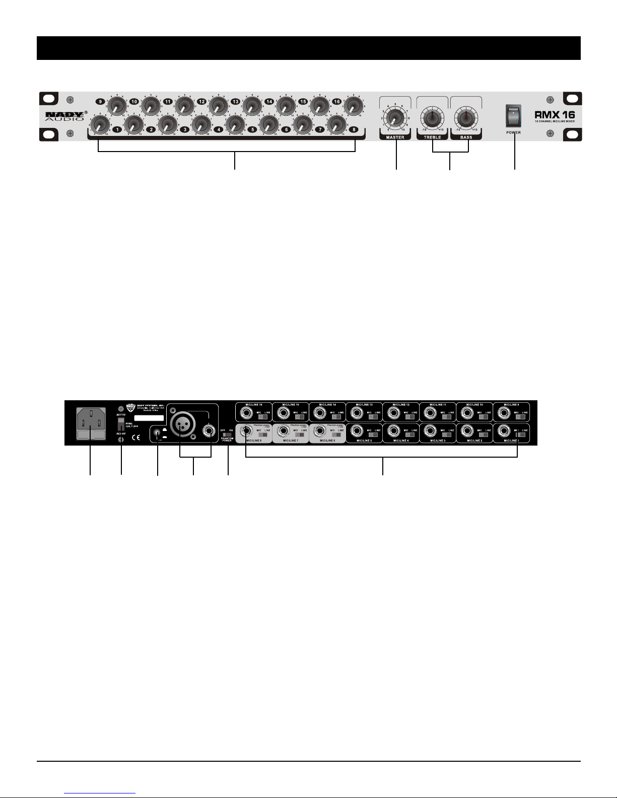
Frequency Response:................................................................ 10Hz—20KHz +/-3dB
Total Harmonic Distortion (THD) + Noise: ............................... 0.1%
S/N Ratio: .................................................................................... >60dB
Tone Controls
Bass:............................................................................................ +/-12dB / 100Hz
Treble:.......................................................................................... +/-12dB / 10KHz
Inputs:.......................................................................................... 16 x MIC (level/impedance): Balanced: 3mV
...................................................................................................... 16 x LINE(level/impedance): Unbalanced: 100mV
Outputs (All controls flat)
High Output: ............................................................................... 1.5V
Low Output: ................................................................................ 0.5V
Impedance (1/4”): ....................................................................... 600 ohms
(XLR):........................................................................................... 600 ohms
LED indicator:............................................................................. Power ON
Fuse Requirements, Type and Size:......................................... T250mA,
...................................................................................................... 5X20mm glass type
Dimensions:................................................................................ 19” x 1.75” x 6.75” (483 x 44 x 170mm)
Weight: ........................................................................................ 5.7 lbs.(2.59 Kg)
One Year Limited Warranty
Nady Systems, Inc. warrants to the original consumer purchaser that the
unit is free from any defects in material or workmanship for a period of one
year from the date of original retail purchase. If any such defect is discovered
within the warranty period, Nady Systems, Inc. will repair or replace the unit
free of charge, subject to verication of the defect or malfunction upon return
to Nady Systems. Please do not return your Nady product to the store where
it was purchased as Nady Systems handles your warranty service directly.
Communication with our Service Department is the most efcient means of
servicing your unit and we are dedicated to keeping you a satised customer.
To the extent permitted by law, any applicable implied warranties, including
warranties of merchantability and tness are hereby limited to one year from
the date of purchase. Consequential or incidental damages resulting from a
breach of any applicable express or implied warranties are hereby excluded.
This warranty is in lieu of all other agreements and warranties, general or
special, express or implied and no representative or person including a Nady
dealer, agent, or employee is authorized to assume for us any other liability in
connection with the sale or use of this Nady Systems’ product.
Whereas some states do not allow limitations on how long implied warranties
last, and do not allow exclusion of incidental or consequential damages, the
above limitations and exclusions may not apply to you. This warranty gives
you specic legal rights and you may also have other rights which may vary
from state to state.
This warranty is subject to the following conditions:
1) This system must have been purchased from an authorized Nady dealer
and all warranty service must be performed by Nady’s service department.
Any service not performed by Nady will automatically void this warranty.
2) Items not covered: physical damage resulting from improper handling of
the unit in transit from the factory by the shipper (Nady Systems is not
responsible for such damage and all such claims must be made against
the shipping company by the consignee); defects caused by normal wear
of the product (expendable parts are typically connectors, cables, poten-
tiometers, switches and similar components); damage or defects caused
by abuse, neglect, accident, failure to connect or operate the unit in any
way that does not comply with applicable technical or safety regulations,
or improper repair, excessive heat or humidity, alteration or unreasonable
use of the unit, causing cracks, broken cases/housings or parts; damage
caused by leaking batteries; nish or appearance items; items damaged
in shipment en route to Nady Systems, Inc. for repair. The warranty is null
and void if any Nady serial number has been removed or defaced.
How To Obtain Service:
1) If factory service is required, you must contact our Service Department at
(510) 652-2411 for a return authorization (RA) number. Make sure the RA
number is clearly marked on the outside of your package. (Please note: if
an RA number is not included, our shipping department cannot accept your
package.)
2) Send the unit back to Nady Systems, 6701 Shellmound Street, Emeryville,
CA, 94608 freight pre-paid. You must include proof of date and place of
purchase (i.e., photocopy of your bill of sale) and a brief description of the
unit’s problem(s) or Nady cannot be responsible for repair or replacement.
Nady Systems, Inc. will not repair, nor be held responsible, for any units re-
turned without proper identication, return address, and RA number clearly
marked on the package.
3) Per the above, Nady will perform all warranty service and return the unit
to you at no charge. Nady Systems will inform the buyer if product sent in
does not meet the terms of this warranty and will provide a quote for xing
the unit and/or shipping it back exclusively at the buyer’s expense.


NADY SYSTEMS, INC. • 6701 SHELLMOUND STREET, EMERYVILLE, CA 94608
Tel: 510.652.2411 • Fax: 510.652.5075 • www.nady.com
Table of contents
Other Nady Audio Music Equipment manuals