Naigon's Electronic Creations Spark 3 R2 User manual

© 2018 by Scott DeBoer, Naigon’s Electronic Creations. Spark™, Igniter™ and Naigon’s Electronic Creations have no affiliation with Lucas Film,
Disney, or its subsidearies.
R4
SPARK 3™ R3 SETUP GUIDE

Page | 2
1. CONTENTS
2. Introduction...........................................................................................................................................................5
2.1. New in Spark 3™...........................................................................................................................................5
2.2. New In Spark 3™ R2 .....................................................................................................................................5
2.3. New in Spark 3™ R3......................................................................................................................................5
2.4. New IN Spark 3™ R4 .....................................................................................................................................5
2.4.1. Drag Mode ...............................................................................................................................................6
2.4.2. Igniter Features........................................................................................................................................6
3. Getting Started ......................................................................................................................................................6
3.1. Important Notes...........................................................................................................................................6
3.1.1. 3.7v Power Supply .............................................................................................................................6
3.1.2. Battery Protection ...................................................................................................................................6
3.1.3. Battery Brands .........................................................................................................................................7
3.1.4. Battery Size ..............................................................................................................................................7
3.1.5. LED Choices..............................................................................................................................................7
3.1.6. Pixel String Choices ..................................................................................................................................7
3.2. Spark 3 Layout..............................................................................................................................................8
3.3. TruDrive™ Separation ..................................................................................................................................9
4. Wiring Diagrams ....................................................................................................................................................9
4.1. Basic Wiring..................................................................................................................................................9
4.2. Flash Wiring................................................................................................................................................10
4.3. RGB Wiring .................................................................................................................................................11
4.4. Single AV Switch Wiring .............................................................................................................................12
4.5. RGBA/RGBW Wiring...................................................................................................................................13
4.6. Color Matching Crystal Matching...............................................................................................................14
4.7. Rumble Motor Wiring ................................................................................................................................15
4.8. Cross-Saber Wiring.....................................................................................................................................16

Page | 3
4.9. X-Saber Wiring ...........................................................................................................................................17
4.10. Pixel String Wiring ......................................................................................................................................18
4.11. Full Wiring ..................................................................................................................................................19
5. Configuration Editing...........................................................................................................................................20
5.1. Installation .................................................................................................................................................20
5.2. Copy Files to your machine ........................................................................................................................22
5.3. Launching The Application .........................................................................................................................22
5.4. Changing Soundfonts .................................................................................................................................24
5.5. EDITING SETTINGS......................................................................................................................................26
5.5.1. Master....................................................................................................................................................26
5.5.2. Motion ...................................................................................................................................................28
5.5.3. Blade ......................................................................................................................................................29
5.5.4. Clash.......................................................................................................................................................31
5.5.5. Blast .......................................................................................................................................................32
5.5.6. Audio......................................................................................................................................................33
5.5.7. Accent ....................................................................................................................................................34
5.6. Generate Dual Out Sounds for Cross-Saber...............................................................................................35
5.7. Format Micro SD ........................................................................................................................................35
5.8. Copy Files Back To The Micro SD................................................................................................................36
6. Error Codes ..........................................................................................................................................................36
7. Saber Operation...................................................................................................................................................37
7.1. Idle Mode ...................................................................................................................................................37
7.1.1. Idle Mode Interaction Table ..................................................................................................................37
7.2. Running Mode............................................................................................................................................37
7.2.1. Running Mode Interaction Table ...........................................................................................................38
7.2.2. Running Interaction for One Button ......................................................................................................38
7.3. Saber Tracks ...............................................................................................................................................39

Page | 4
7.2.3. Saber Tracks Interactivity.......................................................................................................................39
8. Special Thanks .....................................................................................................................................................40

Page | 5
2. INTRODUCTION
Introducing Spark 3™, the entry-level board with top-tier features. Sporting easy configuration, out-of-the-box
motion sensitivity, and a robust true 16bit DAC, this board has motion and audio found only on top-level boards
but at an entry-level price. And with 3 fonts and RGB color-mixing, it’s an all-in-one hilt allowing for light, dark, and
grey warriors all in one hilt. Finally, enjoy some of your favorite tunes using Saber Tracks™, and even turn on the
blade with pulsing effect while the music is playing.
2.1. NEW IN SPARK 3™
There are many improvements in Spark 3™ from the Spark 2™ platform. The following are the main improvements:
HARDWARE
16bit off-CPU DAC for crystal-clear audio from all 8ohm speakers.
Motion Sense V2 ported from Igniter 3™, most accurate motion detection in a production board.
FIRWMARE
Error LED as part of bootstrapper and main app.
oBlinks for SD card error, config file errors, and wav errors
oAlso blinks for warnings such as missing wavs (see <> below)
2.2. NEW IN SPARK 3™ R2
The following features have been added to the S3-R2 release:
EzClash™ improvements. By holding the aux button before performing the clash, the effect will directly go
into the lockup, skipping the clash altogether. If you do a clash and hit the aux, it will behave as before.
This ensures the lockup color will be the actual clash color when starting with holding the main button for
single button installs.
Pixel Support. No longer are you limited by certain brands of pixel strings; now Spark 3™ supports all kinds
of strings on the market, including the notoriously finicky ALotive.
RGBW Pixel Strings! Related to the above addition, Spark 3™ R2 now supports RGBW SK6812 pixel strings.
These can be purchased from BTF Lighting on Amazon among other suppliers.
C4 is now available for use! This means that RGBA or RGBW high-power LEDs can be used with Spark 3™
R2, as well as other accessories like rumble motors.
2.3. NEW IN SPARK 3™ R3
S3-R3 comes with the new RealSwing™ feature! The next iteration in the MotionSense V2 engine, this system
tracks motion in real time, playing the appropriate swing bank and appropriate pitch and volumes as well. This
allows for precise swings that match the motion at any speed. Further, all swing sounds are based off the same
swing files, so it is a more matched sound than smoothswing can provide.
2.4. NEW IN SPARK 3™R4
Spark 3 R4 comes with some exciting new improvements from the previous releases!

Page | 6
2.4.1. DRAG MODE
Spark 3™R4 now has a new drag mode. When holding the saber down and holding the aux button, only the tip
portion of the blade will perform the clash effect, for a neat “drag”effect. The number of pixels that lights up can
be set in the config with the DRAG COUNT NECEditor parameter. Normal lockup will occur with the blade straight
out, up, and angled down. With the parameter set to zero (0), the normal lockup will occur even when the blade is
facing down and the feature will be disabled.
This feature ONLY works when using a pixel blade.
2.4.2. IGNITER FEATURES
The following features have been ported from Igniter:
Saber Cinema™- Use the saber with lights and sounds while the music is playing! Now sound effects and all
lighting effects occur when the saber is in use.
ClashShade, BlastShade, and BladeShade –Allows for variance in the color-sets so that each effect or blade color
varies with each use. Allows a more organic color experience, or with high values even random colors!
3. GETTING STARTED
3.1. IMPORTANT NOTES
PLEASE READ THIS SUBSECTION CAREFULLY AS FAILURE TO DO SO COULD CAUSE DAMAGE TO THE SPARK™
BOARD.
3.1.1. 3.7v Power Supply
Spark 3™ is designed around a 3.7v power supply input. In general, the best way to run a Spark 3™ is to hook up a
single 3.7v battery to the VBATT+ and VBATT-/GND pads.
NEVER HOOK A 7.4V BATTERY DIRECTLY TO A SPARK 3™UNDER ANY CIRCUMSTANCES, OR YOU WILL
DESTROY THE BOARD.
NEVER REVERSE THE POLARITY OF VBATT+ AND VBATT-/GND. IF USING A CONNECTOR FOR THE
BATTERY, MAKE SURE TO USE ONE THAT ONLY CLIPS IN ONE WAY TO PREVENT DAMAGING THE
BOARD BY HOOKING THE POWER IN REVERSE.
3.1.2. BATTERY PROTECTION
Only use li-ion batteries that have a built-in protection circuit. NEVER USE UNPROTECTED CELLS AS THIS CAN
CAUSE DAMAGE TO THE BATTERY AND/OR SPARK 3™. IMR batteries are okay but since they are not
protected they can allow large amounts of power to the board and do not act like a fuse when there is a wiring
issue, so for beginners it is recommended to use the standard Li-ion with the protection circuit.

Page | 7
3.1.3. BATTERY BRANDS
Because only one battery is being used, it is very important that a quality battery is selected to get the best
experience from Spark 3™. From internal testing, it is determined that the best batteries are ones with a 10amp
protection circuit or higher. Specifically, the following batteries meet this criteria:
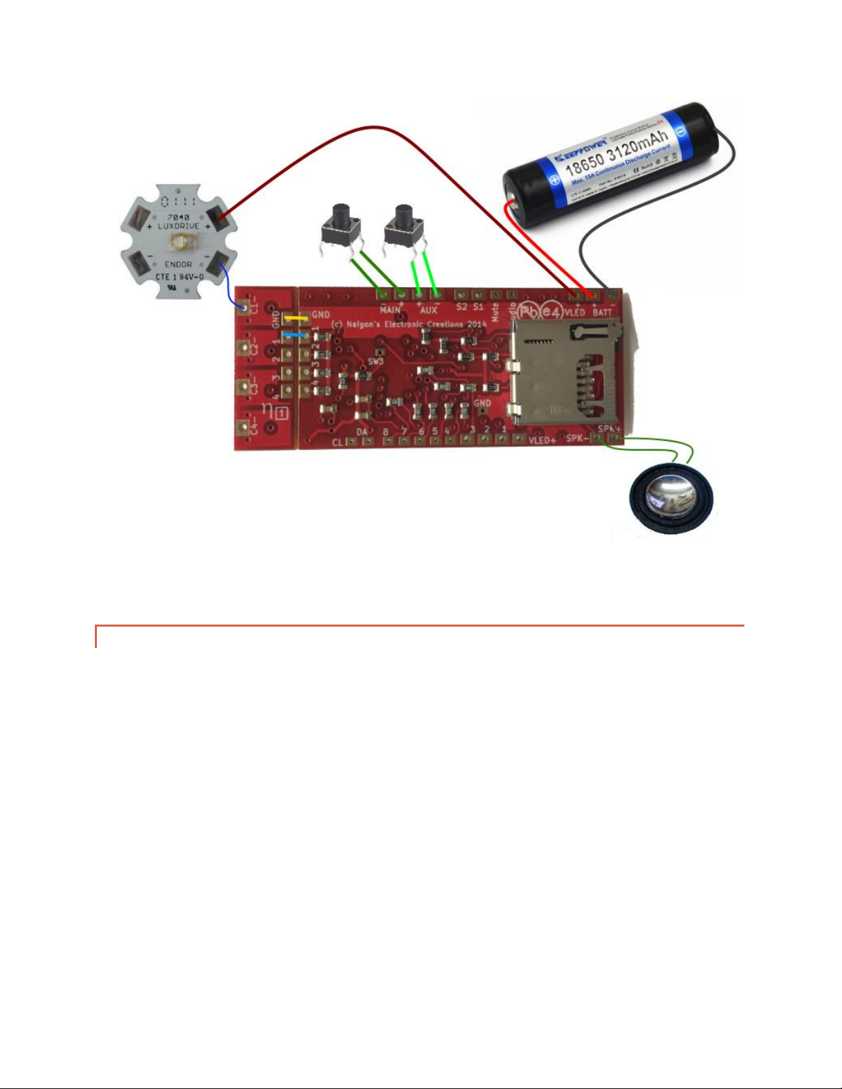
KeepPower 18650 3120mAh 15amp PCB
KeepPower 18650 3400mAh 10amp PCB
Solo’s Hold 18650 15 amp PCB
Solo’s Hold 18650 10 amp PCB
When using a pixel string blade, or a cross-guard setup a 10amp PCB battery MUST be used. Failure to do this will
lead to the board shutting down unexpectedly during effects.
3.1.4. BATTERY SIZE
The best battery to use is an 18650, space allowing. If that cannot be used, then an 18500, 17650, 16650, or 17500
should be used, in that order. 14xxx batteries and 18350 batteries are not recommended due to their shorter life,
and because those batteries may not be able to output enough power to run 4 die of a High Brightness LED
(HBLED).
3.1.5. LED CHOICES
When using Spark 3™ with a 3.7v power source the LEDEngin LEDs will not work well. This is because LEDEngin’s
green and blue dies require a forward voltage of 4.0v for maximum brightness. Thus it is highly recommended to
use the NECree RGB Red/Green/Royal Blue LED sold here at Naigon’s Electronic Creations.
http://saberigniter.com/NECreeRGB.aspx
The NECree RGB produces the brightest, most even blade for an in-hilt LED, but it also is pre-wired for 3.7v with a
diode built-in for the red, so no external resistors are needed. The standard TriCrees work as well but will require a
resistor for red, and a bit more wiring to connect all the positives together.
3.1.6. PIXEL STRING CHOICES
Not all pixel strings are created equal. There are two sizes 5050 and 3535, with the former having better density,
but the latter are thinner and fit in a blade better with less vertical shadowing. The IntelliBlade™ was designed to
be the best of both worlds and is the best choice, but I’ve put that product on hold due to the cost to manufacture
and fragility of shipping making the product not worth the investment.
When purchasing a strip, make sure it has at least 144 LED/M; anything less dense will have way too much corn-
cobbing, with blotches of brightness up the blade.
The best strips currently available to use are the NeoPixel strings from Adafruit:
5050 - https://www.adafruit.com/product/1507
3535 (Skinny) - https://www.adafruit.com/product/2969

Page | 8
That being said, Adafruit’s strips are really over-priced compared to the competition. Sparkfun has very similar
strips that are much more affordable, but still very high quality.
3535 (Skinny) - https://www.sparkfun.com/products/14732
5050 RGBW - https://www.amazon.com/BTF-LIGHTING-Individually-Addressable-Flexible-Non-
waterproof/dp/B01N0MA316?ref_=bl_dp_s_web_14106955011&th=1
Naigon’s Electronic Creations does NOT recommend the Alotive brand strips from Amazon, as they are a cheaper
LED and seem to cause addition line noise from internal testing, though these strips do now work with our
products.
3.2. SPARK 3 LAYOUT
Before getting started, it is important to familiarize yourself with the layout of Spark 3™, TruDrive™ and all of the
pads on the board. This will help in wiring up the board for use in a saber.
The following two diagrams show the important components of Spark 3™, with an accompanying table describing
what each component does.
Figure 1 –Important components on the back of Spark 3™.

Page | 9
Name
Label
Description
1. Micro SD card
holder
NA
Holds the Spark 3™SD card. Ensure the card is fully inserted
before applying power to Spark 3™.
2. TruDrive™
board
LED DRIVER PCB
Driving board that can power two high-power LEDs from Spark
3™. On Spark 3™ only the first three Pads are available.
3. Battery +/-
pads
BAT+, BAT-
Hook power and ground from a 3.7v Li-ion pack here.
4. Speaker pads
SPKR
Hook a 1.5-2.0w, 8ohm speaker here.
5. Accent
Common +
VLED+
Used to power all three of the accent LEDs. Optionally,
additional static LEDs can be powered from this pad. The
output is 3.3v, and it is rated at 200mA.
6. Accent LED
pads
1,2,3
Each pad can hold one 20mA accent LED. These LEDs will be
sequenced by the chosen pattern.
7. LED connect
pads
1,2,3,4
Pads that hook the TruDrive™ board to the Spark 3™ main
board. Pad #4 is not used.
8. Color Pads
C1-, C2-, C3-, C4-
Hook the main LED and flash LED cathodes to these pads.
9. Switch Pads
MAIN, AUX
Pads for the switches. MAIN can be a momentary or latching,
aux must be a momentary. Make sure to select the correct
type of switch for MAIN in the Config Editor.
Table 1–Description of each component.
3.3. TRUDRIVE™ SEPARATION
Spark 3™ will come by default with the TruDrive™ attached to the main board. If it is desired to have the TruDrive™
separate from the main board for the install, then you can detach the two boards.
To separate them, place a mouse pad at the edge of a table, and place Spark 3™ on the pad with the seam where
TruDrive™ meets Spark right at the edge of the table, so that the entire TruDrive™ is off the table and the entire
Spark™ is on the mouse pad. Then with one palm press and hold Spark™ to the pad, and gently use your other
hand to press the other board until it starts to snap. Then simply wiggle the TruDrive™ back and forth until it
comes free.
It is important to note that once the board has been removed it cannot go back on; plan accordingly before
separating the boards.
4. WIRING DIAGRAMS
The following diagrams are the most common to get your board up and running.
Note: It is very important that the correct resistor be used between the negative pad of the LED and C1-, C2-, and
C3- to prevent burning out the LED for warm color LEDs. For Rebel LEDs if a red, red-orange or amber LED is used,
then a 1ohm 1watt resister is needed. For any other Rebel colors a resistor is not needed. The STTH2L06 diode can
be used in place of the resistor and it is a slightly smaller part.
4.1. BASIC WIRING
This is the most basic wiring that is possible to get the board up and running. It is great for testing your Spark 3™
on the bench, or if you are doing a simple install into a saber that will have a removable battery.

Page | 10
Figure 2 –Basic wiring for Spark 3™. This will drive a single main LED and would require a removable battery for charging. Note that a
resistor between the blue wire and C1- of TruDrive™ would be needed if the LED is red, amber, or red-orange.
4.2. FLASH WIRING
Wiring a basic setup to have a TriCree LED with two die of one color and a third die for a flash color is a popular
choice for Spark 3™. This setup allows for a bright single-color blade while still allowing for an effect/aux color for
blast and clash/lockup effects. The wiring diagram below shows how to utilize that setup.
The preferred LED to use for this setup is the TriCree, as it has an optic made specifically for this configuration, and
it has a great balance of brightness with good efficiency, so it doesn’t waste too much power. It also produces a
very even blade when diffused and sanded. The X2/X4 previously recommended is no longer preferred as it’s optic
doesn’t allow enough of the brightness down the tube evenly.

Page | 11
Figure 3 –Wiring a Spark3™ for a main blade and a flash color. Note that the colors can be mixed, so it is possible to have a mix of the two,
or utilize the flash color as the main blade color for one of the three fonts. R1 is needed if the die is Red, Red-orange, or amber.
For this setup with the bridging shown in <>, it is recommended to set c1Color and c2Color, c1Clsh and c2Clsh, and
c1Blst and c2Blast to the same values for a given font to ensure that both LEDs of that same color are enabled.
4.3. RGB WIRING
Spark 3™ supports full RGB color mixing. This diagram shows how to hook up an R/G/rB die for the ultimate color
mixing. The recommended LED to use by far is Naigon’s Electronic Creations own NECree RGrB v2. It utilizes the
highest binned XP-E2 Cree dies, in a common-positive wiring with the STTH2L06 diode already installed, so NO
EXTERNAL RESISTORS ARE REQUIRED for the LED.

Page | 12
Figure 4 –RGrB wiring utilizing the NECree RGB v2 LED. Note that no external resistors are needed with this LED.
4.4. SINGLE AV SWITCH WIRING
Spark 3™ can be controlled with a single switch. When using one switch some find an AV switch to be beneficial as
it incorporates an accent LED and switch into one hole.
The following diagram shows the same RGB wiring with the NECree RGrB LED, but using an AV switch instead of
two tactile switches. It is important to note that a single tactile works fine as well, but it does need to be a
momentary switch for the main button.
Also, when using this wiring configuration, ensure that the Button Layout dropdown is set to either “One Button”
or “One Button w/ Motion” in the NEC Editor.

Page | 13
Figure 5 –Single AV switch wiring with the NECree RGrB LED. It is difficult to see in the picture, but the yellow wire to the switch is hooked to
the pad labeled “+”, purple to “-“, and the two green don’t matter.
4.5. RGBA/RGBW WIRING
With Spark 3™ R2, a fourth die can be utilized for even more flash effects, and a bit more vivid (and efficiently
mixed) colors. The following diagram shows this wiring for a CREE XML RGBW LED, but a quad-rebel or a quad cree
works as well. In general it is recommend to stick with a standard RGB setup for simplicity, but for folks that really
want to do a lot of white/silver colors this may be a choice.

Page | 14
Figure 6 –Cree XML RGBW LED. This allows having a white die, which makes some colors mix more efficiently and a bit brighter clash effects
for some colors. Similar wiring for a quad rebel or quad cree would work as well.
4.6. COLOR MATCHING CRYSTAL MATCHING
With the advent of color mixing many people are wanting a blade matching crystal chamber to go along with their
build. If you want to experience this thrill, then look no further! The following diagram shows how to get this LED
wired and working.
It is important to note that this wiring is applicable to in-hilt LED setups only; when doing a blade matching crystal
for a pixel string, an individual pixel must be used.

Page | 15
Figure 7 - Wiring with an RGB crystal chamber. This will have an RGB led that matches the blade color and pulses with the blade. Note that
all three pins of the REB LED have a resistor since power is coming from the battery. I recommend a 22-33ohm for R1, and a 1ohm each for
R2.
4.7. RUMBLE MOTOR WIRING
When not using a 4th die the C4 pin can be used to run an accessory, such as a rumble motor or another special
accent LED.
The following diagram shows the use of a low power (3.3v) shaft-less motor that can be purchased from Pololu
here. If using something that requires more voltage than 3.3v, the power could be drawn directly from the battery
instead of the VLED+ pin.

Page | 16
Figure 8 –Diagram with a small shaft-less motor running of the C4- pad. For accessories that require more voltage/amperage, direct battery
power can also be used.
4.8. CROSS-SABER WIRING
For those that want to mimic the saber with two side quillion or cross-guard blades that have the delayed
extension, the following wiring diagram is provided. This supports a saber where all three blades are the same
color, with a secondary flash color for either the main blade or all blades.
I’ve provided the wiring for a TriCree though any other LED would be similar. If using a TriCree I recommend only
hooking up two of the three die for the side LEDs to prevent battery drain and to ensure that a single channel does
not get too hot.
Note that when using Red or Amber die resistors would be needed between the die and the appropriate Cn- pad.

Page | 17
Figure 9 –Wiring for the Cross-Saber feature. This is for a single color blade and side guards, but allows for a FOC color on the main blade.
Note that 4 resistors or STTH2L06 diodes would be needed for a Red/amber color, labeled as R1-R4 in the diagram. This wiring also utilizes a
single AV switch, so the configuration would need to reflect that (one button or one button with motion). Finally, c1Color and c2Color could
be set independently if the die off C2- was a different color to allow for the flash-clash effects.
After wiring this, make sure that not only Cross-Saber is enabled in the master section, but each font where it is
desired for the side LEDs to be on will also need C4PERCENT set to 95 in the master, and then C4COLOR set to a
non-zero value for each effect where the secondary blade(s) should be on. If you want a simple static blade then
just set all three c3 values C4COLOR, C4BLST, C4FLSH to 255. However, if you want them to only come on for flash
effects, set C4COLOR to 0, but the rest to 255. You can also turn them down some to something like 155 to save
some power. For C1COLOR and C2COLOR, and C3COLOR, they could be set the same if the TriCree is all red, or set
independently to have c2Color off for the main blade and enabled for the other effects, allowing the main blade to
have a flash-clash color.
4.9. X-SABER WIRING
When using the external XDrive, it is possible to have a cross-guard saber with full color mixing on the main blade
and the two quillions. This specific example uses 3 NECree RGrB LEDs, but any RGB LED could be used.
Note that with this configuration it is recommended to use a 26650 since the runtime drain for this setup is quite
high; if that battery cannot be used at least use the KeepPower 18650 3120mAh as it has a 15amp PCB and does a
bit better with the higher amperage draw.

Page | 18
Figure 10 - Wiring with the XDrive for the X-Saber feature. If TriCrees are used then 3 reisstors/STTH2L06’s would be needed for the red die.
For this wiring, the config will need to be setup just like for the single-color side blades. See 4.8 CROSS-SABER
WIRING on how to do that. Note that C4COLOR will determine if the side blades are on/off, but C1COLOR,
C2COLOR, and C3COLOR set the actual colors for both the main and side blades.
4.10. PIXEL STRING WIRING
Spark 3™ fully supports Pixel string blades, aka WS2812B, out of the box! All that is needed is a separate SD card
with the string blade /dat and /appNN files. These strings are not only super bright, but they also support
Extension and Retraction Flow, allowing for super-realistic growing and shrinking blades, and Impact Blast™, the
ability to replicate bolts hitting the blade in defined spots.
The Pixel strings are quite easy to work with as there are only 3 wires coming out of each strip. When using the
5mm LEDs, these 3 wires are exactly what will be needed. When using the 144 led/meter strips, the two
connections will need to be run in parallel for each strip to light in the same way as the others.
This connector being used is the flat one from TCSS which uses POGO pins.
NeoPixel blades can be built from the 144 led/meter strips:

Page | 19
https://www.adafruit.com/products/2969
or by building a blade from 5mm NeoPixel individual straw-hat LEDs:
https://www.sparkfun.com/products/12999
To see how awesome these look, check out the release video here:
https://www.youtube.com/watch?v=nP17IWlQS6M
IMPORTANT –Because the Pixels use a completely different driver system, the #2-#4 pins are used as simple
grounds when using a string blade. This means that if you want to wire a blade matching crystal chamber, you will
need to use a NeoPixel individual LED wired in parallel with the main blade. Rumble motors are thus not
supported.
Figure 11 –Wiring a back to back style WS2812 blade with two parallel strips. It is also possible to do three strips back to back, which
reduces the vertical shadowing of the blade, but increases the amperage draw. Note that a 0603 resistor on the blade side connector
between 270 to 400ohm should be used.
4.11. FULL WIRING
This diagram shows how to wire a recharge port along with accent LEDs and the NECree RGB v2 LED, allowing all
the features of Spark 3™ to be utilized. The recharge port also acts as a kill key, where pushing a kill plug into the
port will stop power from getting to the board.

Page | 20
Figure 12 –Full wiring using all accent LEDs and a recharge port/kill key combo. This wiring will allow all features of Spark 3™ to be
experienced, including full RGrB color mixing.
5. CONFIGURATION EDITING
Once Spark 3™ has been wired according to the wiring above then it will work immediately with the default
configuration. However, changing the fonts and effects is completely possible and encouraged by using the NEC
Editor. The NEC Editor is the new replacement for the old Config Editors; the NEC Editor is great in that it can edit
every board, and can also work on both Windows and Mac!
5.1. INSTALLATION
On Mac, unzip the file. Double click the DMG. When the NEC Editor pops up, just drag it over to the APP folder, and
this will install the app. I’ve found that on some versions of Mac OS it is necessary to grab near the word NEC
Editor as opposed to the board icon when dragging; trying to grab the icon I results in no action being taken.
This manual suits for next models
2
Table of contents