NAiS LT4H-L User manual

onlinecomponents.com
1
DIN 48 SIZE
DIGITAL TIMER LT4H-L
Timers
Features
1. Economically priced in anticipation
of market needs.
• Economically priced to provide
excellent cost performance.
2. Display is a bright reflective-type
LCD.
3. Inherits all of the characteristics of
the LT4H digital timer.
• Seesaw switches ensure easy
operation.
• IP66 environmental protection.
• Shortened body (70.1 mm 2.760 inch
underhead).
4. UL, C-UL rating approved. CE
compliant.
5. Simultaneous release of DIN48
protective cover (soft type).
• Provides protection for surface and
buttons in dusty environments and from
dirty hands and gloves.
48
1.890
48
1.890 64.5
2.539
Part names
Time delay indicator
DOWN
UP
LOCK
RESET
smh
LOCK
RST
OP.
ON
87654321
Elapsed time display
DIP switches
Set time display
Time units display
Up keys
Down keys
Controlled output indicator
Reset indicator
Lock indicator
Reset switch
Lock switch
TIMER LT4H (Countdown time display)
Product types
UL File No.: E122222
C-UL File No.: E122222
mm inch
Time rangeProduct name Operating mode Output Operating voltage Power down
insurance Terminal type Part number
9.999 s (0.001 s~)
99.99 s (0.01 s~)
999.9 s (0.1 s~)
9999 s (1 s~)
99 min 59 s (1 s~)
999.9 min (0.1 min~)
99 h 59 min (1 min~)
999.9 h (0.1 h~)
DIN48 protective cover (soft type)
LT4H-L
digital timer
Option
Power ON delay (1)
Power ON delay (2)
Signal ON delay
Signal OFF delay
Pulse One-shot
Pulse ON-delay
Signal Flicker
Totalizing ON-delay
(8 modes)
Relay
(1 c)
Transistor
(1 a)
For the LT4H Series
100 to 240 V AC
24 V AC/DC
100 to 240 V AC
24 V AC/DC
12 to 24 V DC
12 to 24 V DC
Available 8 pins
LT4HL8-AC240V
LT4HL8-AC24V
LT4HLT8-AC240V
LT4HLT8-AC24V
LT4HL8-DC24V
LT4HLT8-DC24V
N-TC-48-1
LT4HL 02.1.9 6:25 PM Page 1

onlinecomponents.com
2
LT4H-L
Specifications Type Ralay output type Transistor output type
Item AC type, AC/DC type DC type AC type, AC/DC type DC type
Rating
Rated operating voltage
Rated frequency
Rated power consumption
Rated control capacity
Time range
Time counting direction
Operation mode
Start/Reset input
100 to 240 V AC, 24 V AC/DC
50/60 Hz common
Max. 10 V A
5 A, 250 V AC (resistive load)
9.999 s, 99.99 s, 999.9 s, 9999 s, 99 min 59 s, 999.9 min, 99 h 59 min, 999.9 h (selected by DIP switch)
Addition (UP)/Subtraction (DOWN)
(2 directions selectable by DIP switch)
A (Power ON delay 1), A2 (Power ON delay 2), B (Signal ON delay), C (Signal OFF delay), D (Pulse one-shot),
E (Pulse ON delay), F (Signal Flicker), G (Totalizing ON delay) (selectable by DIP switch)
Min. input signal width: 1 ms, 20 ms (2 directions by selected by DIP switch)
12 to 24 V DC
—
Max. 3 W
100 to 240 V AC, 24 V AC/DC
50/60 Hz common
Max. 10 V A
100 mA, 30 V DC
12 to 24 V DC
—
Max. 3 W
Input signal
Indication
Power failure memory
method
Contact or open collector input Input impedance: Max. 1 kΩ; Residual voltage: Max. 2 V
Open impedance: 100kΩor less, Max. energized voltage: 40V DC
7-segment LCD
EEP-ROM (Min. 105overwriting)
Time
accuracy
(max.)
Contact
Life
Electrical
Mechanical
Operating time fluctuation
Voltage error
Temperature error
Setting error
Contact arrangement
Contact resistance
(Initial value)
Contact material
Mechanical (contact)
Electrical (contact)
Allowable operating
voltage range
Breakdown voltage
(Initial value)
Insulation resistance
(Initial value)
Operating voltage reset
time
Temperature rise
Functional
Destructive
Vibration
resistance
Functional
Destructive
Shock
resistance
± (0.005 % + 50 ms) in case of power on start
± (0.005 % + 20 ms) in case of input signal start
Rated operating voltage: 85 to 110%
Ambient temperature: –10 to +55°C +14 to +131°F
Min. input signal width: 1ms
Timed-out 1 Form C
100 mΩ(at 1 A 6 V DC)
Ag alloy/Au flash
2.0 ×10⁷ope. (Except for switch operation parts)
1.0 ×10⁵ope. (At rated control voltage)
Timed-out 1 Form A (Open collector)
—
—
—
1.0 ×10⁷ope. (At rated control voltage)
85 to 110 % of rated operating voltage
2,000 Vrms for 1 min: Between live and dead metal parts
2,000 Vrms for 1 min: Between input and output
1,000 Vrms for 1 min: Between contacts
Between live and dead metal parts
Min. 100 MΩ: Between input and output (At 500V DC)
Between contacts
Max. 0.5 s
10 to 55 Hz: 1 cycle/min single amplitude of 0.35 mm .014 inch (10 min on 3 axes)
10 to 55 Hz: 1 cycle/min single amplitude of 0.75 mm .030 inch (1 h on 3 axes)
Max. 65° C
(under the flow of nominal operating current at nominal voltage)
—
Min. 98 m 321.522 ft./s2(4 times on 3 axes)
Min. 294 m 964.567 ft./s2(5 times on 3 axes)
Operating
conditions
Ambient temperature
Ambient humidity
Air pressure
Ripple rate
Connection
Protective construction
–10° C to 55° C +14° F to +131° F
Max. 85 % RH
860 to 1,060 h Pa
—
8-pin type
IEC standards IP66 (front panel with rubber gasket)
20 % or less — 20 % or less
LT4HL 02.1.9 6:25 PM Page 2

onlinecomponents.com
3
LT4H-L
Dimensions
• LT4H-L digital timer
(units: mm inch)
Tolerance: ±1.0 ±.039
Terminal layouts and Wiring diagrams
Relay output type Transistor output type
• Dimensions for embedded installation (with adapter installed)
•
Dimensions for front panel installations
•
Installation panel cut-out dimensions
The standard panel cut-out dimensions are shown
below. Use the installation frame (AT8-DA4) and
rubber gasket (ATC18002).
• For connected installations
Note) 1: The installation panel thickness should be between 1
and 5 mm .039 and .197 inch.
Note) 2: For connected installations, the waterproofing ability
between the unit and installation panel is lost.
LT4H
TIMER
RESET
LOCK
UP
hms
OP.
RST
LOCK
DOWN
M48
M1.890
M44.5
M1.752
55.6
2.189 14.5
.571
5.5
.217
7.5
.295
Embedded installation/front panel installation
ATC18002 (supplied)
LT4H
TIMER
UP
OP.
RST
LOCK
DOWN
LOCK
RESET
smh
48
1.890 50
1.969
1
.039
66
2.598
48
1.890 90
3.543
Rubber gasket Installation panel
8-pin type
(8p cap AD8-RC
sold separately)
Installation frame
for embedded installations
AT8-DA4 (supplied)
DIN rail terminal block
(8-pin type AT8-DF8K
sold separately)
Device installation rail
AT8-DLA1
(sold separately)
90
3.543
45+0.6
0
1.772+.024
0
45+0.6
0
1.772+.024
0
80 min.
3.150 min.
80 min.
3.150 min.
45+0.6
0
1.772+.024
0
A
A = (48 ×n – 2.5) +0.6
0
8
5
17
6
2
34
8
5
17
6
2
34
NO
NC
Start
Reset
Start
Reset
Operating
voltage Operating
voltage
LT4HL 02.1.9 6:25 PM Page 3

onlinecomponents.com
4
LT4H-L
Setting the operation mode, time range, and time
Setting procedure 1) Setting the operation mode and time range
Set the operation mode and time range with the DIP switches on the side of the timer.
DIP switches
Setting procedure 2) Setting the time
Set the set time with the keys (UP and DOWN keys) on the front of the timer.
DIP switch
Item DIP switch No.
123
ON ON ON A: Power on delay 1
OFF OFF OFF A2: Power on delay 2
ON OFF OFF B: Signal on delay
OFF ON OFF C: Signal off delay
ON ON OFF D: Pulse One shot
OFF OFF ON E: Pulse On delay
ON OFF ON F: Signal Flicker
OFF ON ON G: Totalizing On delay
Table 1: Setting the operation mode
Table 2: Setting the time range
Operation mode
Operation mode Refer to table 1
1
2
3Minimum input reset and
start signal width 20 ms 1 ms
*4
Time delay direction Addition
Subtraction
5
Time range Refer to table 2
6
7
8
ONOFF
DIP switch No.
678
ON ON ON 0.001 s to 9.999 s
OFF OFF OFF 0.01 s to 99.99 s
ON OFF OFF 0.1 s to 999.9 s
OFF ON OFF 1 s to 9999 s
ON ON OFF 0 min 01 s to 99 min 59 s
OFF OFF ON 0.1 min to 999.9 min
ON OFF ON 0 h 01 min to 99 h 59 min
OFF ON ON 0.1 h to 999.9 h
Time range
Notes: 1) The DIP switches are set as ON before shipping.
2) Set the DIP switches before installing the timer.
3) When the DIP SW setting is changed, turn off the power once.
DIP switches (Note)
ON
87654321
QElapsed time display
WSet time display
ETime delay indicator
RControlled output indicator
TReset indicator
YLock indicator
UTime units display
IUP keys
Changes the corresponding digit of the
set time in the addition direction
(upwards)
ODOWN keys
Changes the corresponding digit of the
set time in the subtraction direction
(downwards)
PRESET switch
Resets the elapsed time and the output
{LOCK switch
Locks the operation of all keys on the unit
9
8
7
2
3
4
5
6
11
10
DOWN
UP
LOCK
RESET
sm
1
h
LOCK
RST
OP.
LT4HTIMER
• Changing the set time
1. It is possible to change the set time
with the up and down keys even dur-
ing time delay with the timer.
However, be aware of the following
points.
1) If the set time is changed to less than
the elapsed time with the time delay set
to the addition direction, time delay will
continue until the elapsed time reaches
full scale, returns to zero, and then
reaches the new set time. If the set time
is changed to a time above the elapsed
time, the time delay will continue until the
elapsed time reaches the new set time.
2) If the time delay is set to the subtrac-
tion direction, time delay will continue
until “0” regardless of the new set time.
2. If the set time is changed to “0,” the
unit will operate differently depending
on the operation mode.
1) If the operation mode is set to A
(power on delay 1) or A2 (power on
delay 2), the output will turn on when the
power supply is turned on. However, the
output will be off while reset is being
input.
2) In the other modes, the output turns
on when the start is input. When the
operation mode is C (signal off delay), D
(Pulse one shot), or F (Signal flicker),
only when the start input is on does the
output turn on. Also, when the reset is
being input, the output is off.
Front display section
• Power failure memory
The EEPROM is used for power failure memory. It has a life of Min. 105over-writings.
The EEPROM is overwriting with the following timing.
Output mode Overwrite timing
Power ON delay (2) A2 When power is OFF
Addition G Change of preset value or start, reset input
When power is OFF after being ON
Other modes When power is OFF after changing preset value
LT4HL 02.1.9 6:25 PM Page 4

onlinecomponents.com
5
LT4H-L
Operation mode T: Set time t1, t2, t3, ta<T
Operation type
Power on delay (1)
Explanation Time chart
• Set the operation mode
section of the DIP switches
(no.’s 1, 2, and 3) on the
side of the timer as shown.
• Clears elapsed time value and starts time
delay at power ON.
• After timer completion, stops at the display of
the set value (addition), or stops at “0” (sub-
traction).
• Ignores start input.
A
Power on delay (2)
A2
Signal on delay
B
Signal off delay
C
TT
ON
OFF
ON
OFF
ON
OFF
Reset
Output
Power
supply
T T
ON
OFF
ON
OFF
ON
OFF
Reset
Output
Power
supply
T T
ON
OFF
ON
OFF
ON
OFF
ON
OFF
Start
Reset
Output
Power
supply
T>t1 T>t2
t2t1T
ON
OFF
ON
OFF
ON
OFF
ON
OFF
Start
Reset
Output
Power
supply
123
ON ON ON
• Set the operation mode
section of the DIP switches
(no.’s 1, 2, and 3) on the
side of the timer as shown.
• Elapsed time value does not clear at power
ON. (power outage countermeasure func-
tion)
• The output remains ON even after the power
is cut and restarted.
• After timer completion, stops at the display of
the set value (addition), or stops at “0” (sub-
traction).
• Ignores start input.
123
OFF OFF OFF
• Set the operation mode
section of the DIP switches
(no.’s 1, 2, and 3) on the
side of the timer as shown.
• Clears elapsed time value at power ON.
• Time delay starts at start ON and elapsed
time value or output resets at start OFF.
• Instantaneous time delay start at reset OFF
and power ON while start is ON.
• In order to have the time delay start at power
ON or reset at power OFF, short out the start
input beforehand.
123
ON OFF OFF
• Set the operation mode
section of the DIP switches
(no.’s 1, 2, and 3) on the
side of the timer as shown.
• Clears elapsed time value at power ON.
• Output control ON at start ON and time delay
start at start OFF.
• Elapsed time value clears when start goes ON
again during time delay.
123
OFF ON OFF
Note: Each signal input (start and reset) is applied by shorting their input terminal to the common terminal Q.
LT4HL 02.1.9 6:25 PM Page 5

onlinecomponents.com
6
LT4H-L
Operation type
Pulse One-shot
Explanation Time chart
• Set the operation mode
section of the DIP switches
(no.’s 1, 2, and 3) on the
side of the timer as shown.
• Clears elapsed time value at power ON.
• Time delay starts and output control ON at
start ON.
• Control output OFF at time up, and elapsed
value cleared.
• Ignores start input during time delay.
• In order to have the time delay start at power
ON or reset at power OFF, short out the start
input beforehand.
D
Pulse On delay
E
Signal Flicker
F
Totalizing On delay
G
ON
OFF
ON
OFF
ON
OFF
ON
OFF
T>ta T>tb
ta tbTT
Start
Reset
Output
Power
supply
ON
OFF
ON
OFF
ON
OFF
ON
OFF
TTT
Start
Reset
Output
Power
supply
ON
OFF
ON
OFF
ON
OFF
ON
OFF
T>ta
taTTT
Start
Reset
Output
Power
supply
ON
OFF
ON
OFF
ON
OFF
ON
OFF
T>taT=t1+t2
tat2t1T
Start
Reset
Output
Power
supply
123
ON ON OFF
• Set the operation mode
section of the DIP switches
(no.’s 1, 2, and 3) on the
side of the timer as shown.
• Clears elapsed time value at power ON.
• Time delay starts at start ON.
• Ignores start input during time delay.
• In order to have the time delay start at power
ON or reset at power OFF, short out the start
input beforehand.
123
OFF OFF ON
• Set the operation mode
section of the DIP switches
(no.’s 1, 2, and 3) on the
side of the timer as shown.
• Clears elapsed time value at power ON.
• Time delay starts at start ON.
• Ignores start input during time delay.
• Output control reverses, elapsed time value
clears, and timer delay starts at timer comple-
tion.
• In order to have the time delay start at power
ON or reset at power OFF, short out the start
input beforehand.
123
ON OFF ON
• Set the operation mode
section of the DIP switches
(no.’s 1, 2, and 3) on the
side of the timer as shown.
• Elapsed time value does not clear at power
ON. (power outage countermeasure function)
• The output remains ON even after the power
is off and restarted.
123
OFF ON ON
Note: Each signal input (start and reset) is applied by shorting their input terminal to the common terminal Q.
T: Set time t1, t2, t3, ta<T
LT4HL 02.1.9 6:25 PM Page 6

onlinecomponents.com
7
PRECAUTIONS IN USING THE LT4H-L
1. Terminal wiring
1) When wiring the terminals, refer to the
terminal layout and wiring diagrams and
be sure to perform the wiring properly
without errors.
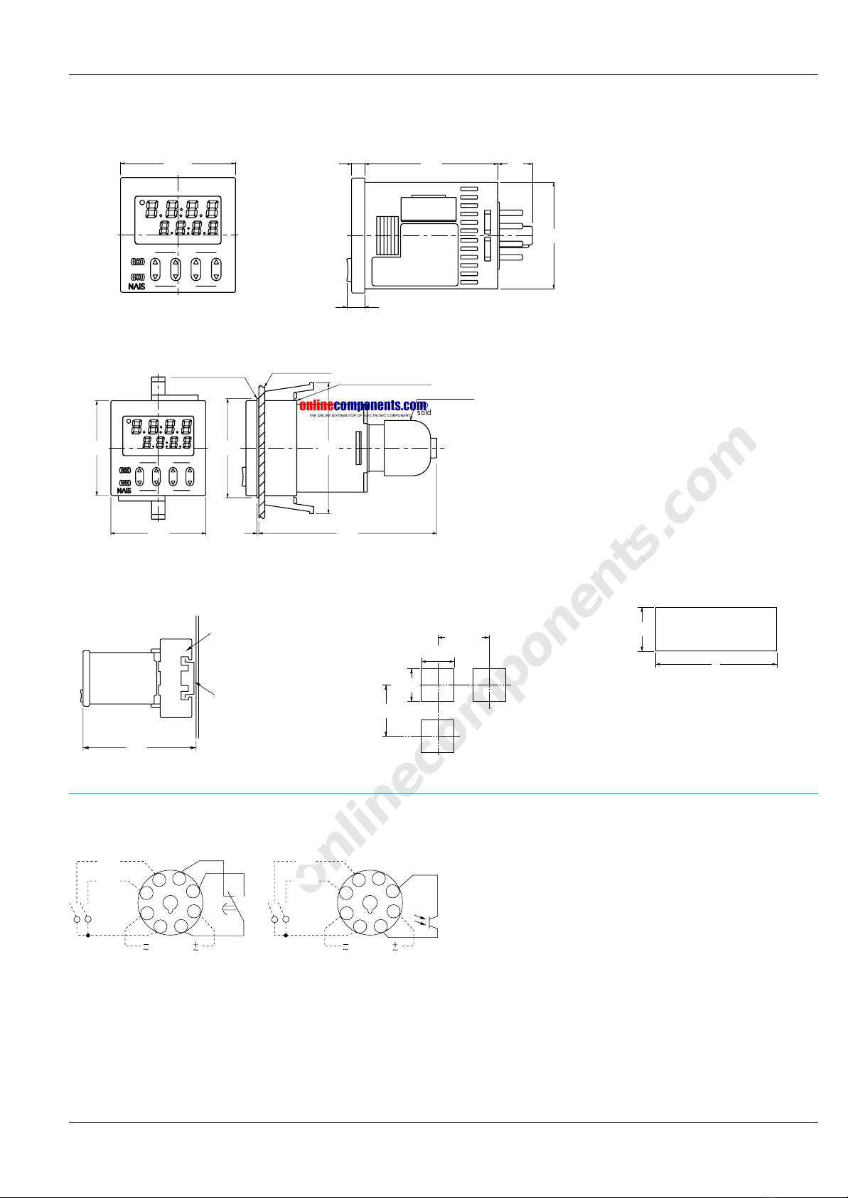
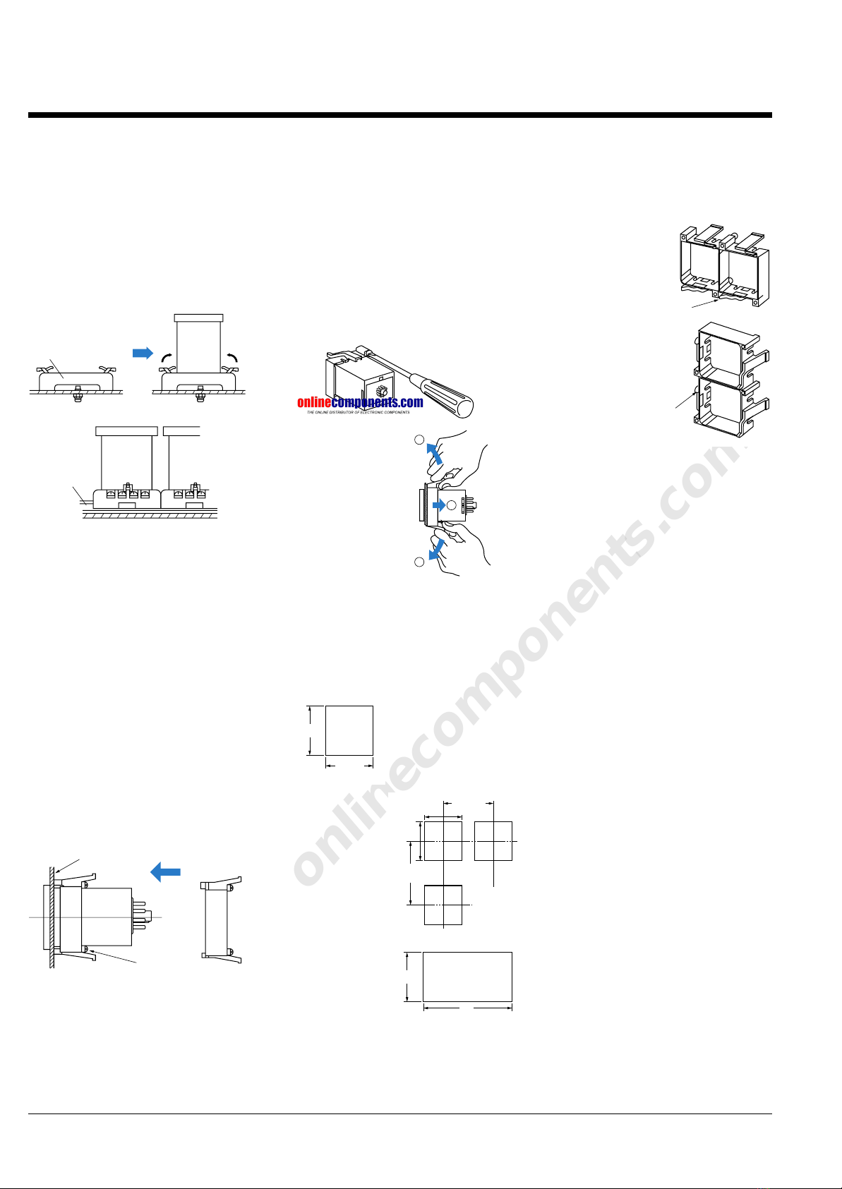
2) When using the instrument with an
embedded installation, use either the
rear terminal block (AT78041) or the 8P
cap (AD8-RC). Avoid soldering directly to
the round pins on the unit.
When using the instrument with a front
panel installation, use the DIN rail
terminal block (AT8-DF8K).
3) After turning the unit off, make sure
that any resulting induced voltage or
residual voltage is not applied to power
supply terminals Wthrough U. (If the
power supply wire is wired parallel to the
high voltage wire or power wire, an
induced voltage may be generated
between the power supply terminals.)
4) Have the power supply voltage pass
through a switch or relay so that it is
applied at one time. If the power supply
is applied gradually, the counting may
malfunction regardless of the settings,
the power supply reset may not function,
or other such unpredictable occurrence
may result.
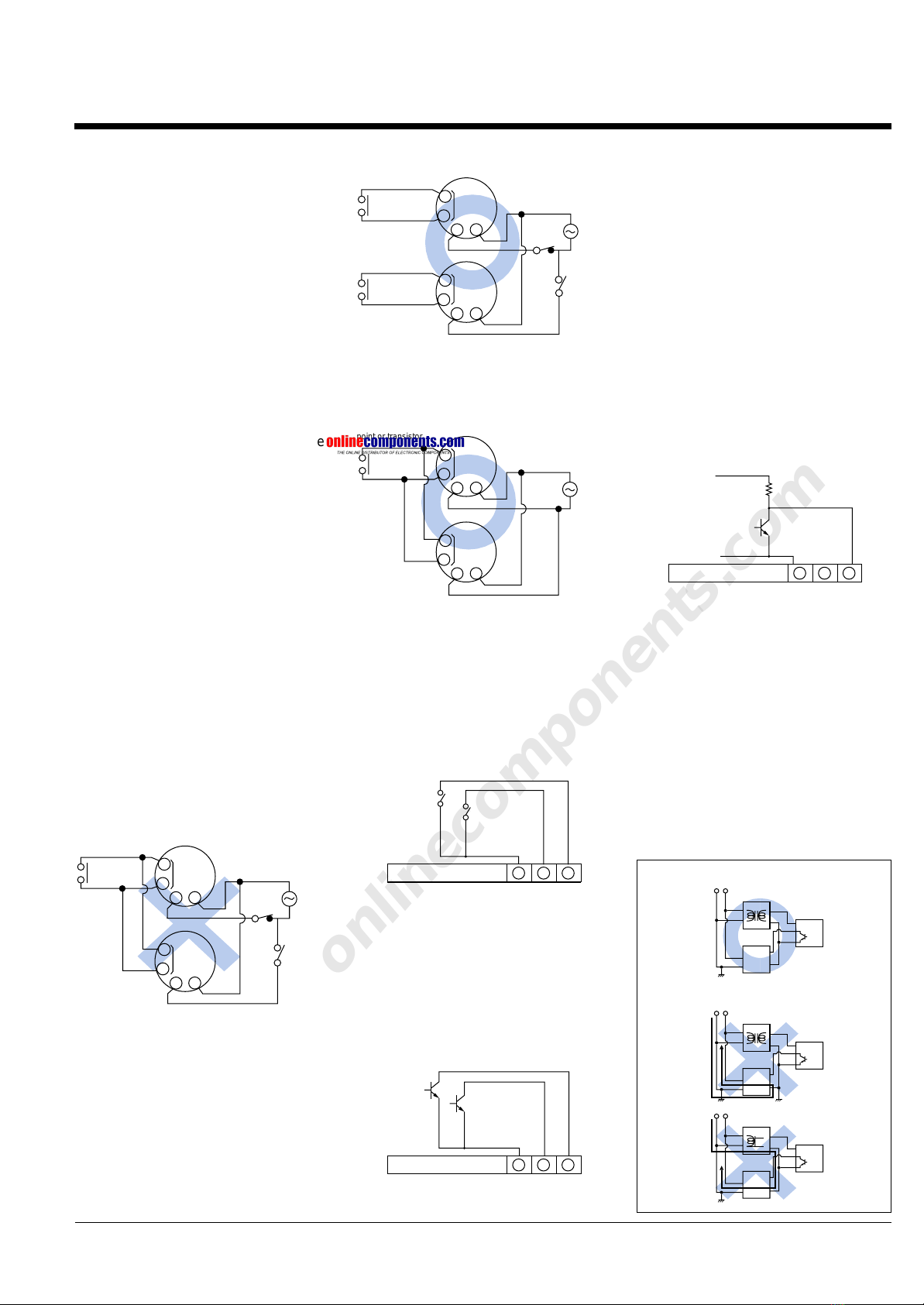
2. Input connections
The power circuit has no transformer.
When an input signal is fed to two or
more timers at once, do not arrange the
power circuit in an independent way.
If the timer is powered on and off
independently as shown in Fig. A, the
timer’s internal circuitry may get
damaged.Be careful never to allow such
circuitry.
If independent power circuitry must be
used, keep the input contacts or
transistors separate from each other, as
shown in Fig. B.
When power circuitry is not independent,
one input signal can be fed to two or
more timers at once, as shown in Fig. C.
3418-pin type
Start input
Reset input
Q
12 to 40V DC
Reset input
3418-pin type
(The above example is for reset input)
(Fig. B) Incorrect
(−)
(−)
(−)
(−)
(+)
(Fig. A) Correct
Timer
Input device
(sensor, etc.)
Insulated
transformer
AC power supply
AC current
wraparound
Timer
Timer
Input device
(sensor, etc.)
Input device
(sensor, etc.)
(−)
(+)
(−)
(+)
Insulated
transformer
Single coil
trance
AC power supply
AC power supply
(Fig. A)
Input contact
point or transistor
Input
terminal Power
supply
127
127
Input
terminal
(Fig. B)
Input contact
point or transistor
Input contact
point or transistor
127
127
Input
terminal
Input
terminal
Power
supply
(Fig. C)
Input contact
point or transistor
127
127
Input
terminal
Input
terminal
Power
supply
3. Input and output
1) Signal input type
(1) Contact point input
Use highly reliable metal plated contacts.
Since the contact point’s bounce time
leads directly to error in the timer
operations, use contacts with as short a
bounce time as possible. Also, select a
minimum input signal width of 20 ms.
(2) Non-contact point input
Connect with an open collector. Use
transistors whose characteristics satisfy
the criteria given below.
VCEO = 20 V min.
IC= 20 mA min.
ICBO = 6µA max.
Also, use transistors with a residual
voltage of less than 2 V when the
transistor is on.
* The short-circuit impedance should be
less than 1 kΩ.
[When the impedance is 0 Ω, the current
coming from the start input and stop
input terminals is approximately 12 mA,
and from the reset input and lock input
terminals is approximately 1.5 mA.]
Also, the open-circuit impedance should
be more than 100 kΩ.
* As shown in the diagram below, from a
non-contact point circuit (proximity
switches, photoelectric switches, etc.)
with a power supply voltage of between
12 and 40 V DC, the signal can be
input without using an open collector
transistor. In the case of the diagram
below, when the non-contact point
transistor Q switches from off to on
(when the signal voltage goes from
high to low), the signal is input.
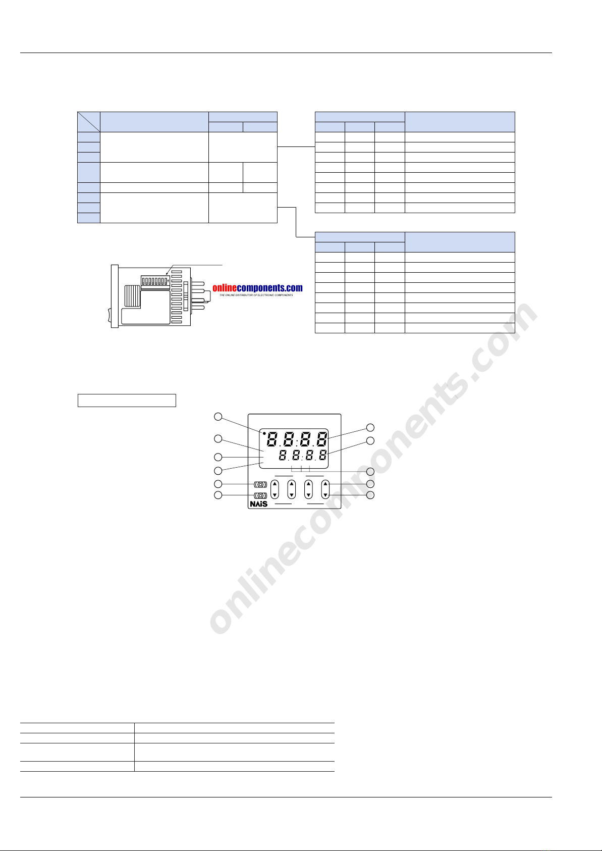
2) The input mode and output mode
change depending on the DIP switch
settings. Therefore, before making any
connections, be sure to confirm the
operation mode and operation conditions
currently set.
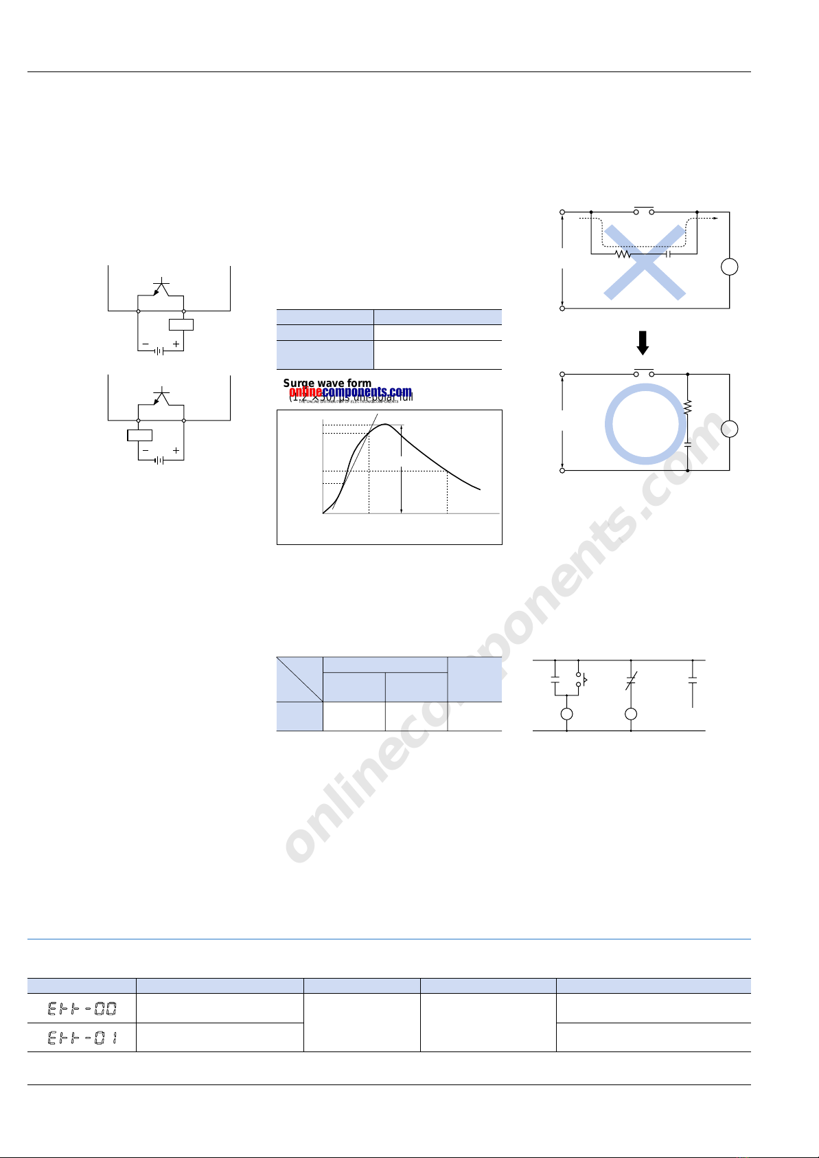
3) Input device power supply does not
use a transformer, so to prevent short
circuits when connecting the signal
inputs, use a power supply for input
devices such as sensors that has its
primary and secondary isolated as
shown in Fig. A, and in which the
secondary is not earthed.
Start input
Reset input
3418-pin type
LT4HL 02.1.9 6:25 PM Page 7

onlinecomponents.com
8
PRECAUTIONS IN USING THE LT4H SERIES
Display Contents
Malfunctioning CPU. Enter reset input, RESET
key, or restart unit.
The values at start-up before the CPU
malfunction occurred.
0
Malfunctioning memory. See
note.
OFF
Output condition Restoration procedure Preset values after restoration
7. Self-diagnosis function
If a malfunction occurs, one of the following displays will appear.
Note: Includes the possibility that the EEPROM’s life has expired.
4) Regarding external noise, the values
below are considered the noise-resistant
voltages. If voltages rise above these
values, malfunctions or damage to the
internal circuitry may result, so take the
necessary precautions.
5) When connecting the operating power
supply, make sure that no leakage
current enters the timer. If you use a
contact protection circuit such as that
shown in Fig. A, leak current can flow
back through the CR circuit and cause
erroneous operation. For this reason,
use the circuit shown in Fig. B.
6) Long periods of continuous operation
in the time-up completed condition (one
month or more) will result in the
weakening of the internal electrical
components from the generated heat
and, therefore, should be avoided. If you
do plan to use the unit for such
continuous operation, use in conjunction
with a relay as shown in the circuit in the
diagram below.
• Surge wave form
[± (1.2 ×50) µs uni-polar full wave voltage]
100
90
50
30
00 1.2 Time (µs) 50
Peak
Surge voltage (%)
Operating
power supply
C
R
Leakage current
Operating
power supply
T
T
(Fig. A)
CR
(Fig. B)
Receive output
from contact
at relay R
TimerRelay
RRTR
TR
Timer
As NPN output
Load’s power supply
Load’s power supply
Timer
As PNP output
Load
Load
4) The input signal is applied by the
shorting of each input terminal with the
common terminal. Never connect other
terminals or voltages higher than 40V
DC, because it may destroy the internal
circuitry.
5) Transistor output
(1) Since the transistor output is
insulated from the internal circuitry by
a photocoupler, it can be used as an
NPN output or PNP (equal value)
output.
6) When wiring, use shielded wires or
metallic wire tubes, and keep the wire
lengths as short as possible.
7) For the load of the controlled output,
make sure that it is lower than the rated
control capacity.
4. Operation of LT4H digital timer
1) Turning on and off the power supply
while operating in A2* (Power on delay
2) or G (Totalizing On delay) will result in
a timer error to be generated due to the
characteristics of the internal circuitry.
Therefore, use the start input or stop
input.
* Not related to the start input.
2) When controlling the timer by turning
on the power supply, use only A (Power
on delay 1) or A2 (Power on delay 2).
Use of other modes in this situation will
result in timer errors. When using the
other modes, control the timer with the
start input or stop input.
5. Operation mode and time range
setting
The operation mode and time range can
be set with the DIP switches on the side
of the timer. Make the DIP switch
settings before installing the timer on the
panel.
Noise wave form (noise simulator)
Rise time: 1 ns
Pulse width: 1 µs, 50 ns
Polarity: ±
Cycle: 100 cycles/second
6. Conditions of usage
1) Avoid locations subject to flammable
or corrosive gases, excessive dust, oil,
vibrations, or excessive shocks.
2) Since the cover of the timer is made of
polycarbonate resin, avoid contact with
or use in environments containing methyl
alcohol, benzene, thinners, and other
organic solvents; and ammonia, caustic
sodas, and other alkaline substances.
3) If power supply surges exceed the
values given below, the internal circuits
may become damaged. Be sure to use
surge absorbing element to prevent this
from happening.
Operating voltage
Surge voltage (peak value)
AC type 6,000V
DC type
AC/DC type 1,000V
Power supply terminals Input
terminals
AC type DC type
AC/DC type
Noise
voltage 1,500V 1,000V 600V
LT4HL 02.1.9 6:25 PM Page 8

onlinecomponents.com
9
DIN SIZE TIMERS COMMON OPTIONS
Terminal sockets (Unit: mm inch, Tolerance: ±1 ±.039)
Appearance Dimensions Terminal wiring
(Top view) Mounting hole dimensions
• DIN rail socket (8-pin)
Part No.:
ATC180031
Note: Terminal No.
on the main body are
identifical to those on
the terminal socket.
65 43
78 12
50
1.969
40
1.575
2-4.5 dia.
2-.177 dia.
70
2.756 70
2.756
35.3
1.390
4
.157
24
.945
19
.748
1287
4356
2-M4 2-M.157
screw holes
(or 4.2±0.1 .165±0.1
dia. holes)
The minimum distance
between the holes which
are parallel drilled.
50
1.969
70
2.756
13
.512
40±0.2
1.575±.008
24
.945
70
2.756
50
1.969
Note: The socket’s numbering system matches that of the timer terminals.
Sockets (Unit: mm inch, Tolerance: ±1 ±.039)
Appearance Dimensions Terminal wiring
(Top view) Mounting hole dimensions
—
3456
2187
38
1.496
21
.827
16
.630
41
1.614
8712
5643
Mounting parts
Note: The socket’s numbering system matches that of the timer terminals.
41
1.614
21
.827
38
1.496
• Rear terminal socket
Part No.:
AT78041
—
31.4 dia.
1.236 dia.
32.5 dia.
1.280 dia. (34.6) (1.362)
26
1.024
8.6
.339
8
.315
30 dia.
1.181 dia.
14 dia.
.551 dia.
1
2
3
4
5
6
7
8
31.4 dia.
1.236 dia.
34.6
1.362
30 dia.
1.181 dia.
• 8P cap
Part No.:
AD8-RC
• Rubber gasket
Part No.:
ATC18002
Part No.:
ATL58011
• Mounting rails (Applicable for
DIN and IEC standards)
Part No.:
AT8-DLA1
Length: 1 m
aluminum
• Fastening plate
• DIN48 protective cover
(soft type)
The rubber gasket is
enclosed in the timer.
• Mounting frame
Part No.:
AT8-DA4
Part No.:
ATA4806
Part No.:
N-TC-48-1
The rubber gasket is
enclosed in the timer.
For holding DIN rails
50.0
1.969 1.0
.039
50.0
1.969
48
1.890
48
1.890
68
2.677
26
1.024
4
.157
2.75R .108R
10
1515
10
15 5515
.394 .591.591.394 .591 .197.197.591
5.5
.217
1,000±1
39.37±.039
35
1.378 24
.945 1.5
.059
Oval hole, 40-5.5×15 40-.217×.591
27
1.063
7.5
.295
UP
ATA4806
50.0
1.969
12
.472 M4 .157
10
.394
10
.394
49.4
1.945
10.0
.394
49.4
1.945
Accessories
• Panel cover (Black)
DOWN
UP
LOCK
RESET
LT4H
TIMER
The black panel cover is also
available so that you can change
the appearance of the panel by
changing the panel cover. The
color of the standard panel cover
is ash gray.
LT4HL 02.1.9 6:25 PM Page 9

onlinecomponents.com
10
INSTALLATIONS
Installations
1. Surface mount
1) Put the terminal socket on the board
directly or put it on the DIN rail (Fig. 1).
2) Insert the timer into the terminal
socket and fix it with clip (Fig. 2)
3) On DIN rail mounting, mount the timer
on the DIN rail tightly to get the proper
dimension. (Fig. 3)
4) 8-pin type should be connected with
terminal socket (AT8-DF8K).
5) DIN rail (AT8-DLA1) is also available
(1 m).
2. Flush mount
1) The mounting frame (AT8-DA4) and
rubber gasket (ATC18002 for surface
waterproofing) that are available at extra
costs are necessary. If the pin
connection socket is the 8-pin type, use
the 8P cap (AD8-RC).
2) How to mount the timer
From the panel front, pass the timer
through the square hole. Fit the
mounting frame from the rear, and then
push it in so that the clearance between
the mounting frame and the panel
surface is minimized. In addition, lock the
mounting frame with a screw.
3) Caution in mounting the timer
• If the PM4H and the LT4H series are
used as the waterproof types, tighten the
reinforcing screws on the mounting
frames so that the timers, the rubber
gaskets, and the panel surfaces are
tightly contacted with each other.
(Tighten the two screws with uniform
force and make sure that there is no
rattling. If the screws are tightened too
excessively, the mounting frame may
come off.)
• If the timer is installed with the panel
cover and the rubber gasket removed,
the waterproofing characteristic is lost.
4) Installation
Loosen the screws on the mounting
frame, spread the edge of frame and
remove it.
5) Correctly connect the pins while
seeing the pin connection diagram.
6) The rear terminal block (ATC78041)
or the 8P cap (AD8-RC) is necessary to
connect the pins, and avoid directly
soldering the round pins on the timer.
7) Panel cutout dimensions
The standard panel
cutout dimensions are
shown in the left
figure. (Panel
thickness: 1 to 5 mm
.039 to .197 inch)
8) Although the
timers can be
mounted adjacent
to each other in
this case, it is
recommended to
arrange the
mounting holes
as shown in the
right figure to
facilitate attaching
and detaching the
mounting frame.
9) Adjacent
mounting
Although the timers can be mounted
adjacent to each other, remember that
the panel surface of timer will lose its
water-resistant effect. (Panel thickness:
1 to 5 mm .039 to .197 inch)
Guideline values for dimension A when
installing n units in sequence are as
follows:
A = (48 ×n – 2.5) (mm)
When lining up the
timers horizontally,
set the frames in
such a position so
the formed spring
areas are at the top
and bottom.
When lining up the
timers vertically, set
the frames in such
a position as the
formed spring
areas are at the
right and left.
+0.6
+0
Pull the mounting
frame backward
while spreading out
its hooks with your
thumbs and index
fingers.
45+0.6
0
1.772+.024
0
45+0.6
0
1.772+.024
0
45+0.6
0
1.772+.024
0
45+0.6
0
1.772+.024
0
80 mm
3.150 inch
or more
80 mm
3.150 inch
or more
A
45+0.6
0
1.772+.024
0
Formed
spring
Formed
spring
(Fig. 2)(Fig. 1)
Terminal socket
(Fig. 3)
DIN rail
1
2
1
Push in
Screw
Panel
LT4HL 02.1.9 6:25 PM Page 10

onlinecomponents.com
ARCT1B188E 200112-1.5YT
Please contact ..........
Specifications are subject to change without notice. Printed in Japan.
Automation Controls Company
KHead Office: 1048, Kadoma, Kadoma-shi, Osaka 571-8686, Japan
KTelephone: Japan (81) Osaka (06) 6908-1050
KFacsimile: Japan (81) Osaka (06) 6908-5781
http://www.nais-e.com/
COPYRIGHT © 2001 All Rights Reserved
Matsushita Electric Works, Ltd.
These materials are printed on ECF pulp.
These materials are printed with earth-friendly vegetable-based (soybean oil) ink.
GLOBAL NETWORK
MUSA Aromat Corporation
629 Central Ave., New Providence, N.J. 07974 U.S.A.
Tel: 1-908-464-3550 (Headquarters)
•New Jersey
•Georgia
•Massachusetts
•Illinois
•Texas
•California
Los Angeles
San Jose
•Michigan
Canada Aromat Canada, Inc.
Europe
Asia
MSingapore Matsushita Electric Works (Asia Pacific) Pte. Ltd.
101 Thomson Road, #25-03/05, United Square, Singapore 307591
Tel: 65-255-5473
Malaysia Matsushita Electric Works (Malaysia) Sdn. Bhd.
Thailand Matsushita Electric Works Sales (Thailand) Co., Ltd.
U.A.E. Matsushita Electric Works (Middle East) FZE.
MChina Matsushita Electric Works (China) Co., Ltd.
Suite 201 Level 2 Tower W3, The Toners, Oriental Plaza, No. 1,
East Chang An Ave., Dong Cheng District, Beijing, 100005 China
Tel: 86-10-8518-1302, 1303
Beijing Matsushita Electric Works (China) Co., Ltd.
Shanghai Matsushita Electric Works (China) Co., Ltd. Shanghai Branch Office
Guangzhou Matsushita Electric Works (China) Co., Ltd. Guangzhou Branch Office
Dalian Matsushita Electric Works (China) Co., Ltd. Dalian Branch Office
Shenzhen Matsushita Electric Works (China) Co., Ltd. Shenzhen Branch Office
Chengdu Matsushita Electric Works (China) Co., Ltd. Chengdu Branch Office
MHong Kong Matsushita Electric Works (Hong Kong), Ltd.
Rm1601, 16/F, Tower 2,
The Gateway, 25 Canton Road,
Tsimshatsui, Kowloon, Hong Kong
Tel: 852-2529-3956
MJapan Matsushita Electric Works, Ltd.
Automation Controls Company
1048, Kadoma, Kadoma-shi, Osaka 571-8686, Japan
Tel: 81-06-6908-1050
North & South America http://www.aromat.com/
http://www.mew-europe.com/
Representative Office
• Indonesia
• Vietnam
• Philippines
• India
• Turkey
• Brazil
M
Germany Matsushita Electric Works (Europe) AG
Rudolf-Diesel-Ring 2, D-83607 Holzkirchen, Germany
Tel: 49-8024-648-0
Germany Matsushita Electric Works Deutschland G.m.b.H.
United Kingdom Matsushita Electric Works UK Ltd.
•Ireland
Matsushita Electric Works UK Ltd. Irish Branch Office
Austria Matsushita Electric Works Austria G.m.b.H.
Switzerland Matsushita Electric Works Schweiz AG
France Matsushita Electric Works France S.A.R.L.
Italy Matsushita Electric Works Italia s.r.l.
Benelux Matsushita Electric Works Benelux B.V.
Spain Matsushita Electric Works España S.A.
•Portugal
Matsushita Electric Works España S.A. Portuguese Branch Office
Czech Matsushita Electric Works (CZ) s.r.o.
Scandinavia Matsushita Electric Works Scandinavia AB
LT4HL 02.1.9 6:25 PM Page 12
This manual suits for next models
3
Table of contents