9
English
1. CAUTIONS FOR HANDLING AND OPERATION
■Read these warnings and cautions carefully and only use in the manner intended.
■These warnings and cautions are intended to avoid potential hazards that could result in personal injury to the
operator or damage to the device. These are classi¿ed as follows in accordance with the seriousness of the risk.
Class Degree of Risk
WARNING A safety hazard could result in bodily injury or damage to the device if
the safety instructions are not properly followed.
CAUTION A hazard that could result in light or moderate bodily injury or damage to
the device if the safety instructions are not followed.
WARNING
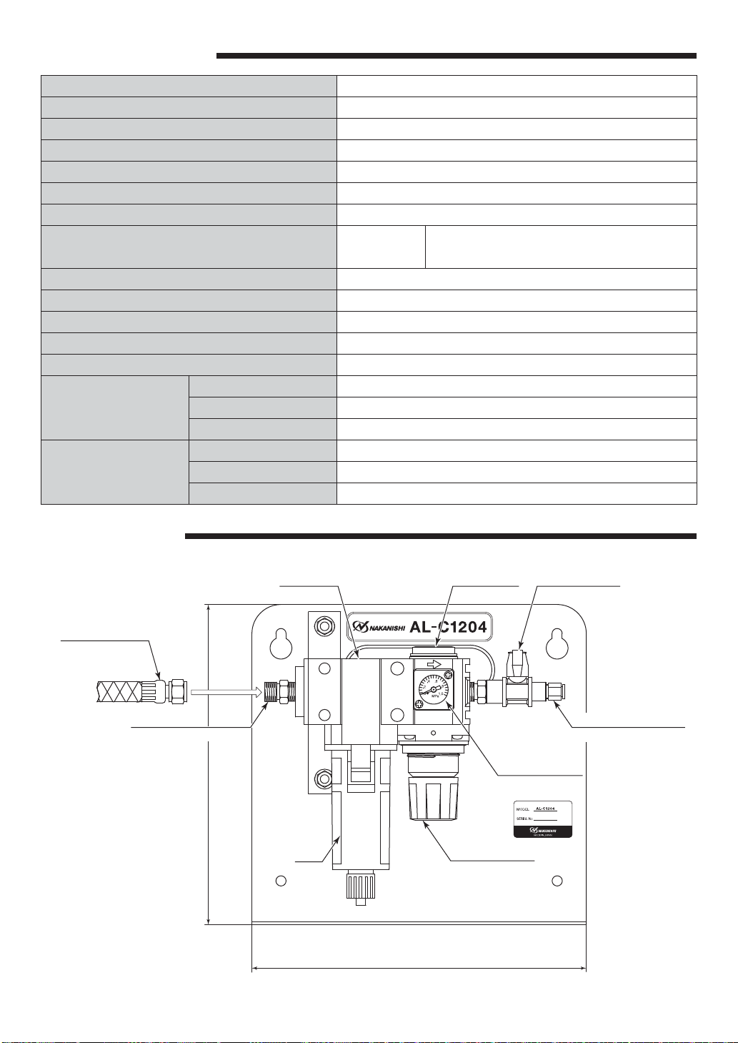
①Handling
Connection to the Air Line Kit should be performed by a person with experience with
compressed air and air compressors.
②Air Pressure
Compressed air is required. Do not exceed an air pressure of 1.0MPa (145psi) at primary side
and 0.85MPa (123.3psi) at secondary side of the Air Line Kit.
③Use of Clean Air
Do not use compressed air contaminated with chemicals, oil compounds, organic solvents,
salinity or corrosive gasses in order to avoid damage to the device.
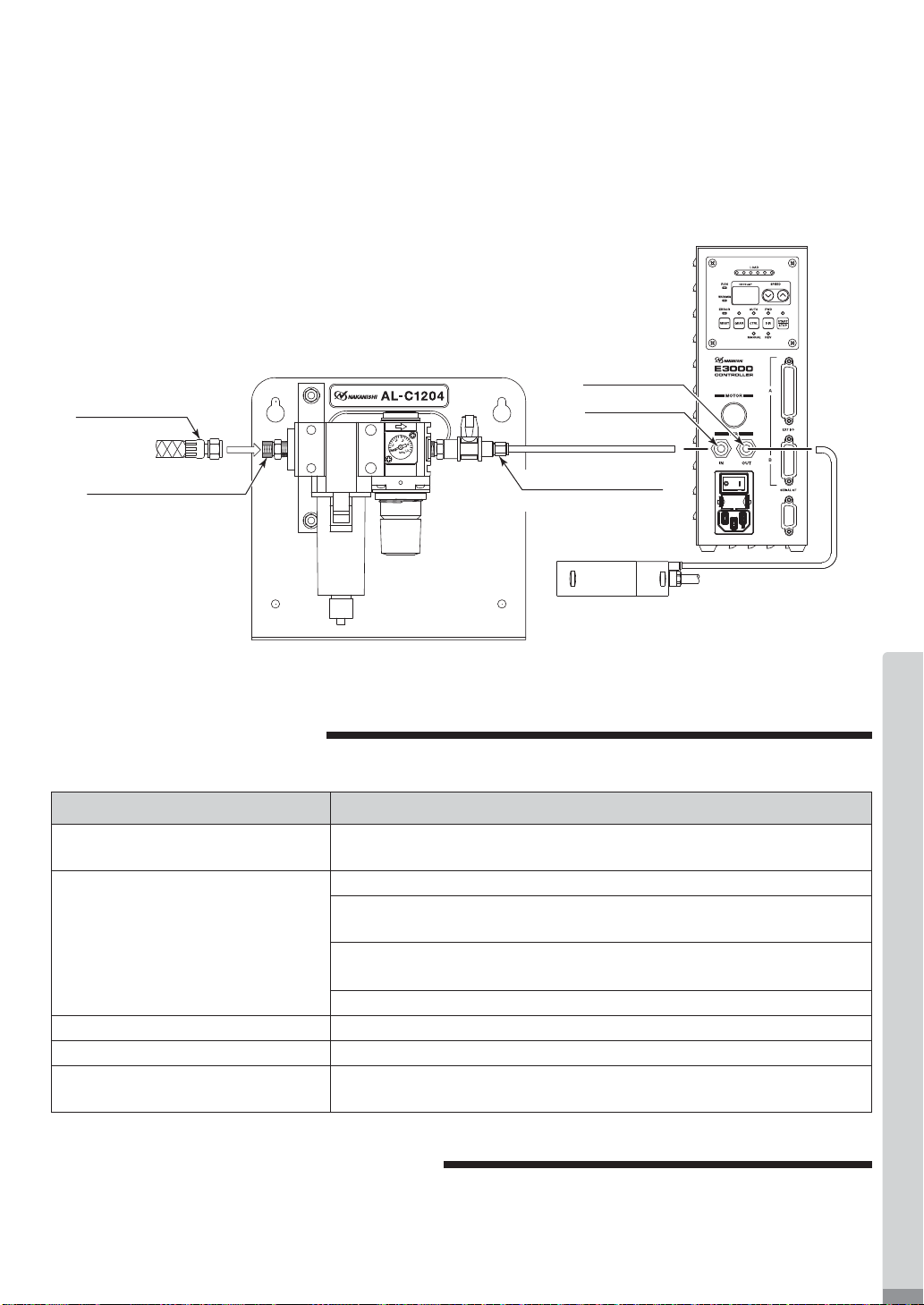
④Connection of connection hose and supply air hose
Connect the input connection hose and supply air hose securely to avoid accidental
disconnection during use. Input air pressure should never exceed 1.0MPa (145psi).
Pressure exceeding 1.0MPa (145psi) may cause the connection hose and supply air hose to
rupture.
⑤Inlet and Outlet Connections
Do not hit, impact or cause shock to the Inlet or Outlet Connector Connections. Never put undo
stress or load on the Inlet or Outlet Connector Connections. Any damage to these components
can cause air leakage and the inability of the inlet or outlet quick disconnect to adequately
secure the connection hose and supply air hose.
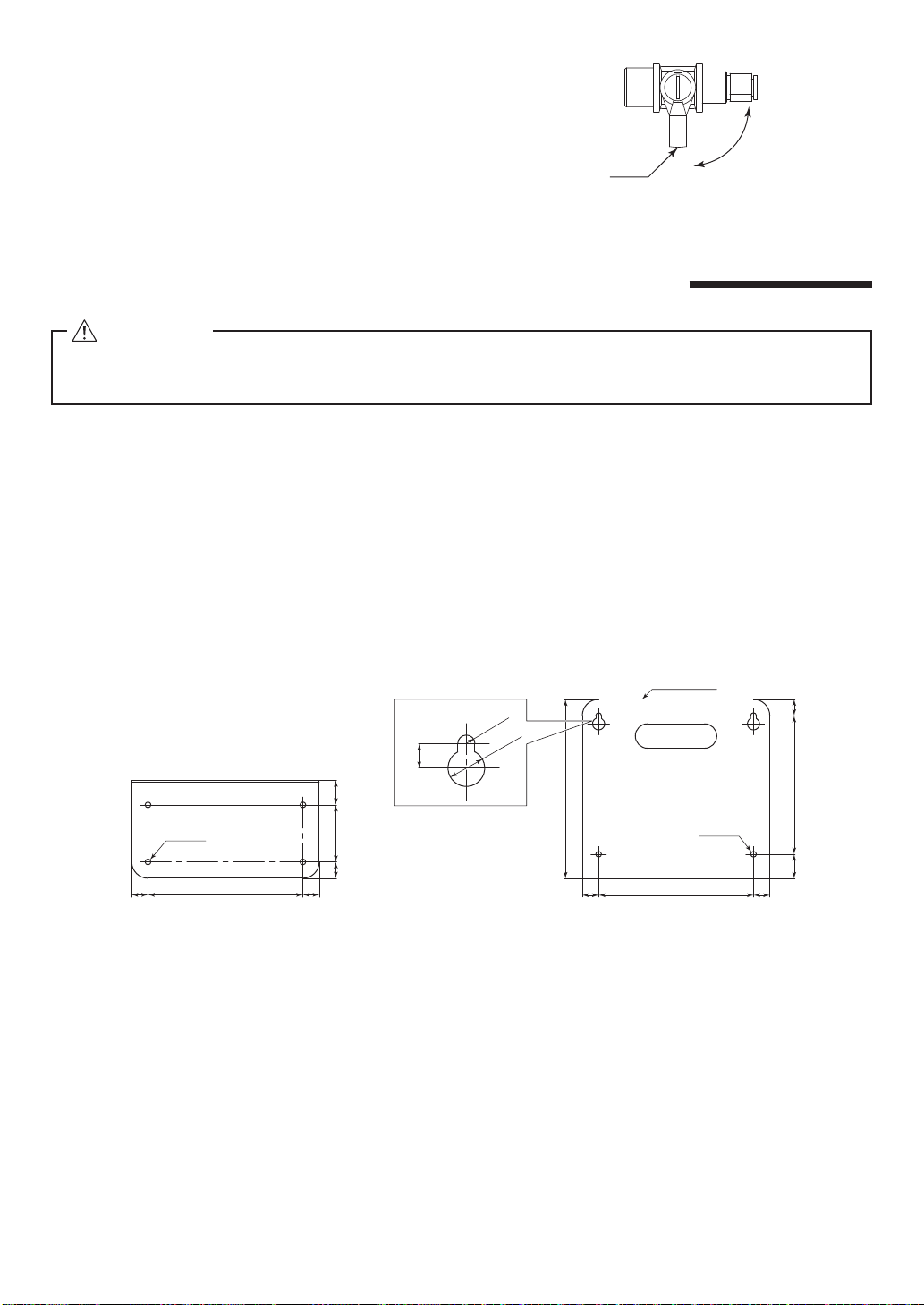
⑥Mounting the Air Line Kit
When installing the Air Line Kit, securely install the Air Line Kit by mounting it on a Àat, level
surface. If the Air Line Kit is dropped, damage to the Air Line Kit and injury to the operator is
possible.
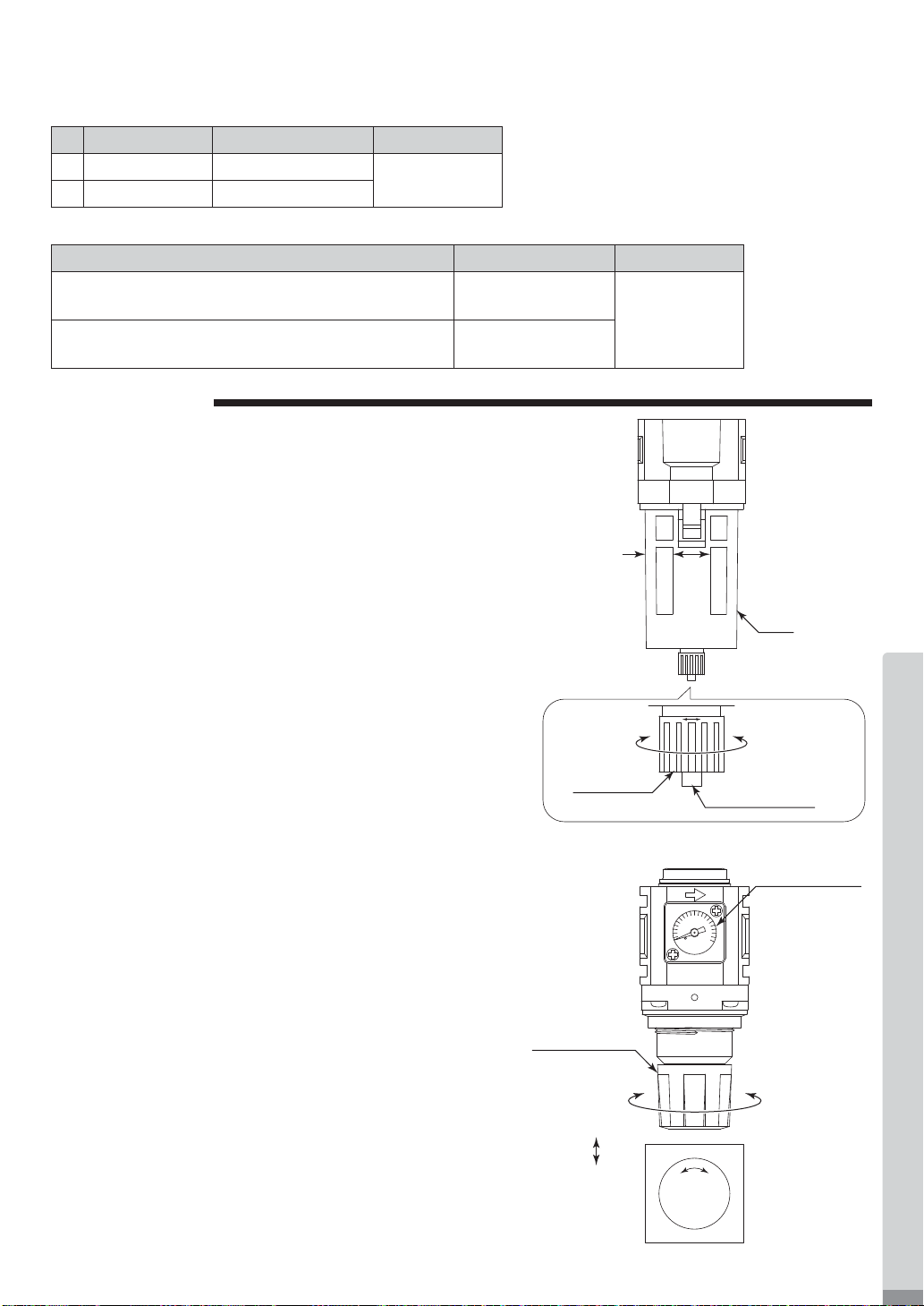
⑦Air Regulator Bowl
・The bowl is made of a polycarbonate.
Do not use the Air Line Kit in conditions where chemicals or organic solvents are present in
the atmosphere.
・Do not remove the bowl guard. Using the Air Line Kit without the bowl guard may cause
injury to the operator should the bowl burst.
・When removing the bowl from the regulator, remove all pressure from the Input and Output
sides of the Air Line Kit.
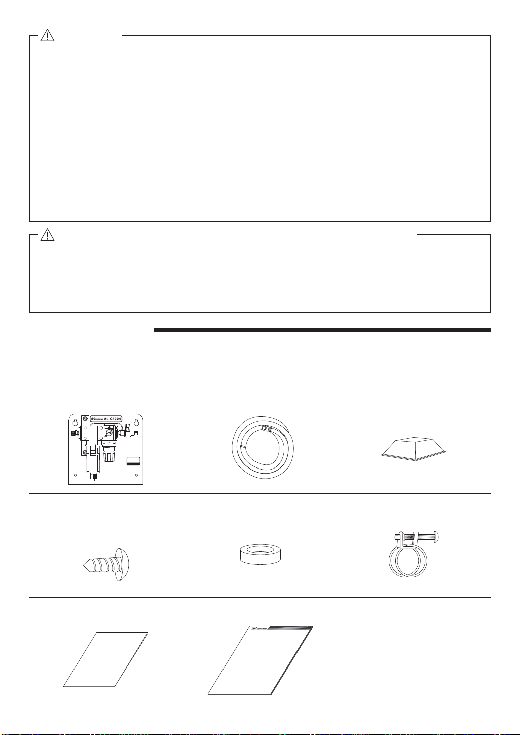
Thank you for purchasing the "AL - C1204" Air Line Kit. This Air Line Kit will supply clean and dry cooling air to the
motor and spindle. THIS AIR LINE KIT IS NOT A SUBSTITUTE FOR AN AIR DRYER.
Read this and all the associated component Operation Manuals carefully before use. Always keep this Operation
Manual in a place where a user can referred to for reference at any time.