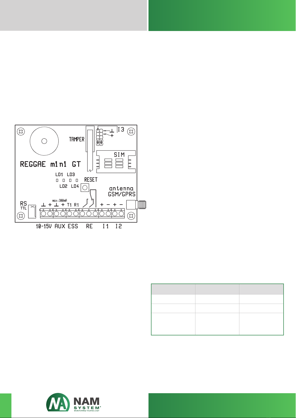
Uninsulated voltage input I3:
The communicator has one voltage uninsulated input
I3. The input connector is implemented by using 2 pins
situated on the two-row pin lath. The input pins are mar-
ked“+” and “GND” in the row next to the marking “I3”.
The pin marked “+” is the live terminal input, the second
pin of the input is marked “GND” is connected to the
ground of the communicator.
The communicator recognizes two function statuses at
this input – closed and released. It is possible to close the
input by connecting the pins together. The resistance for
each input status is shown in the table. It is possible to
switch the input at voltage levels shown in the table. For
switching inputs it is possible to use outputs with open
collectors of the connected ESS panel.
In order to close the input, the appropriate voltage level
must be at the input longer than the time set in the con-
figuration of the communicator (100ms – fast input or
300ms – slow input).
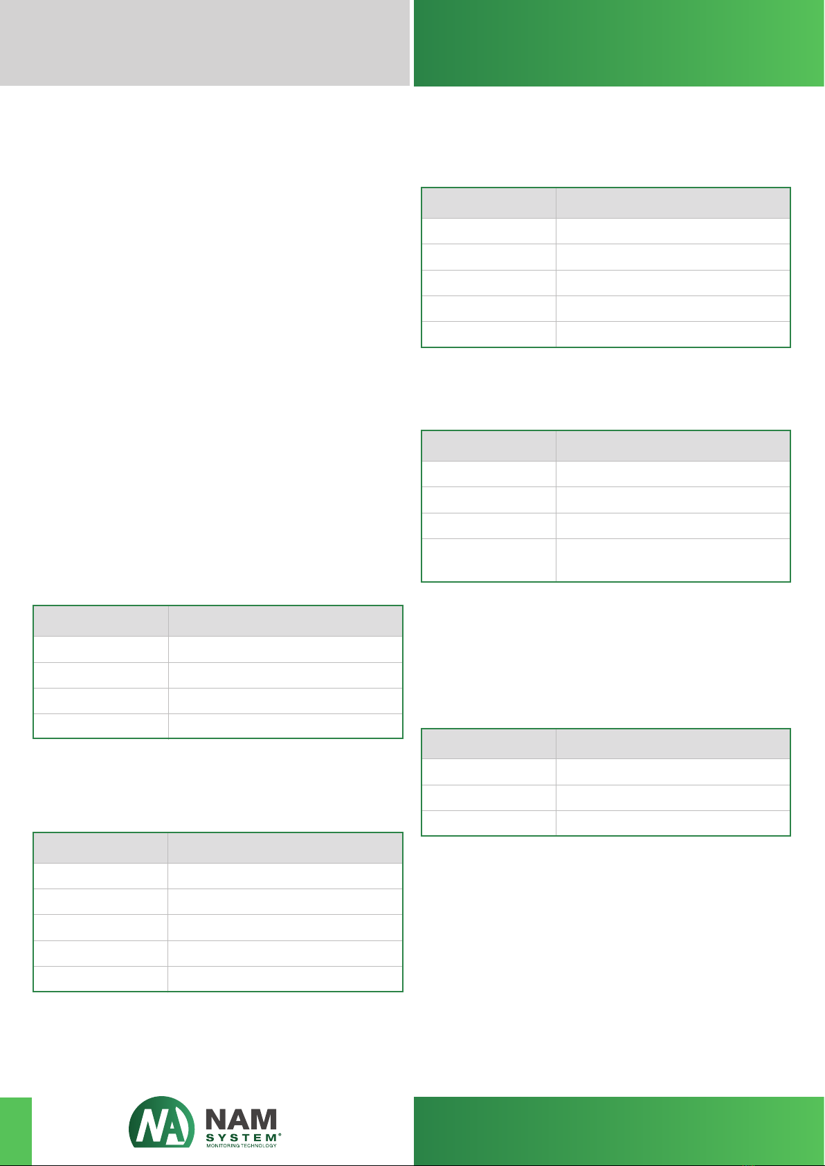
The table below shows the reactions to the inflowing vol-
tage respectively the connected resistance for input I3
Diagnostics and congurations serial port RS-TTL:
The connector of serial port RS-TTL serves for using dia-
gnostic and configuration software on the PC. The level
of these serial ports is TTL (3V). This serial port is not in-
sulated from the remaining parts of the communicator.
The programming cable RS/USB for REGGAE mini GT is
used to connect the circuit board of the REGGAE mini
GT communicator and PC. Please contact the producer,
NAM system, a.s. for this type of cable.
Status of input
closed – alarm
Unspecified status
Released –
idle-circuit
condition
Voltage at input
-15 V to +1.5 V
+1.5 V to +1.8 V
+1.8 V to +15 V
Resistance at input
0 to 1.5 kΩ
1.5 to 2.2 kΩ
> 2.2 kΩ
Relay output
On the circuit board of the REGGAE mini GT communica-
tor there is one relay output RE with one contact switch.
The terminal plate markings are standard. The mutual
outlet of the switch contact is marked„C“ (Common). The
contact outlet that is clamped close when the status is
idle-circuit is marked „NC“ (Normally-Closed). The con-
tact outlet that is in release when the status is idle-circuit
is marked„NO“ (Normally-Open).
The carrying capacity relay output is a maximum of
1 A / 30VDC (respectively 0.3 A / 60VDC) or 0.5 A / 125 VAC.
Supply output AUX
Supply of output AUX is achieved by using the terminal
plates marked„AUX“ and„GND“. This output is meant for
possible supply of the circuit of the voltage insulated in-
puts I1 and I2 on the circuit board of the REGGAE mini GT
communicator. The AUX output is not insulated from the
remaining parts of the communicator REGGAE mini and
so its usage for supplying any of the inputs I1 or I2 leads
to the breach of the insulation of the inputs involved.
During operation of the circuit board of the REGGAE mini
GT at a supply voltage of 13.8 V, the AUX output allows
direct current voltage in the range of 12.3 – 13.6V depen-
ding on the connected consumption. During operation
of the communicator using the back-up accumulator,
the voltage at the AUX output changes according to the
state of the accumulator and may fall to a value of 8.0 V.
The maximum power consumption of the AUX output is
300 mA at a temperature of approximately +25 °C.
The AUX output is protected from short-circuiting by a
return safety fuse. This guarantees the limiting of power
coming from the short-circuit of the output to less than
100 mA.
USER MANUAL
www.namsystem.com
REGGAE mini GT/GTbz
Communicator for GPRS transmission
7