NAM system REGGAE Series User manual

USER MANUAL
REGGAE GT/GTbz
Communicator for
GSM (GPRS/SMS) transmission
Document: 1.60

CONTENT
CONTENT . . . . . . . . . . . . . . . . . . . . . . . . . . . . . . . . . . . . . . . . . . . . . . . . . . . . . . . . . . . . . . . . . 2
INTRODUCTION . . . . . . . . . . . . . . . . . . . . . . . . . . . . . . . . . . . . . . . . . . . . . . . . . . . . . . . . . . . . . 3
OPERATING CONDITIONS . . . . . . . . . . . . . . . . . . . . . . . . . . . . . . . . . . . . . . . . . . . . . . . . . . . . . . . 4
DESCRIPTION OF COMMUNICATORS REGGAE GT/GTBZ/GTBZXXX . . . . . . . . . . . . . . . . . . . . . . . . . . . . . 5
Basic technical parameters . . . . . . . . . . . . . . . . . . . . . . . . . . . . . . . . . . . . . . . . . . . . . . . . . . . . . 5
Circuit board of REGGAE GT communicator. . . . . . . . . . . . . . . . . . . . . . . . . . . . . . . . . . . . . . . . . . . 6
Powering REGGAE GT communicators . . . . . . . . . . . . . . . . . . . . . . . . . . . . . . . . . . . . . . . . . . . . . . 7
Voltage of insulated inputs . . . . . . . . . . . . . . . . . . . . . . . . . . . . . . . . . . . . . . . . . . . . . . . . . . . . . . . . 7
Diagnostic and configuration of serial port RS1 . . . . . . . . . . . . . . . . . . . . . . . . . . . . . . . . . . . . . . . . . . . 8
Communication serial port RS2 . . . . . . . . . . . . . . . . . . . . . . . . . . . . . . . . . . . . . . . . . . . . . . . . . . . . . 8
Relay outputs . . . . . . . . . . . . . . . . . . . . . . . . . . . . . . . . . . . . . . . . . . . . . . . . . . . . . . . . . . . . . . . . 8
RESET button. . . . . . . . . . . . . . . . . . . . . . . . . . . . . . . . . . . . . . . . . . . . . . . . . . . . . . . . . . . . . . . . . 9
Indication of the state of the communicator - LED lights . . . . . . . . . . . . . . . . . . . . . . . . . . . . . . . . . . . . . 9
Antenna connector - GSM/GPRS . . . . . . . . . . . . . . . . . . . . . . . . . . . . . . . . . . . . . . . . . . . . . . . . . . . 10
Telephone unit of communicator . . . . . . . . . . . . . . . . . . . . . . . . . . . . . . . . . . . . . . . . . . . . . . . . . . . 10
Tampers on the communicator . . . . . . . . . . . . . . . . . . . . . . . . . . . . . . . . . . . . . . . . . . . . . . . . . . . . 10
Power source circuit board - REGGAE. . . . . . . . . . . . . . . . . . . . . . . . . . . . . . . . . . . . . . . . . . . . . . 11
Powering the REGGAE GTbz/GTbzxxx communicators . . . . . . . . . . . . . . . . . . . . . . . . . . . . . . . . . . . . . 11
Back-up accumulator. . . . . . . . . . . . . . . . . . . . . . . . . . . . . . . . . . . . . . . . . . . . . . . . . . . . . . . . . . . 11
Supply output AUX . . . . . . . . . . . . . . . . . . . . . . . . . . . . . . . . . . . . . . . . . . . . . . . . . . . . . . . . . . . . 11
LED indicators on the power source circuit board. . . . . . . . . . . . . . . . . . . . . . . . . . . . . . . . . . . . . . . . . 12
Safety fuses . . . . . . . . . . . . . . . . . . . . . . . . . . . . . . . . . . . . . . . . . . . . . . . . . . . . . . . . . . . . . . . . . 12
Operating time of REGGAE GT/GTbz/GTbzxxx communicators using the back-up accumulator . . . . . . . . . . . 12
Modules RS422/485 a RS23 . . . . . . . . . . . . . . . . . . . . . . . . . . . . . . . . . . . . . . . . . . . . . . . . . . . . 13
Connecting modules RS422/485 . . . . . . . . . . . . . . . . . . . . . . . . . . . . . . . . . . . . . . . . . . . . . . . . . . . 13
Connecting modules RS232 . . . . . . . . . . . . . . . . . . . . . . . . . . . . . . . . . . . . . . . . . . . . . . . . . . . . . . 13
INSTALLATION OF THE COMMUNICATOR REGGAE GT/GTBZ/GTBZXXX . . . . . . . . . . . . . . . . . . . . . . . . . 14
Location requirements for communicator REGGAE GT. . . . . . . . . . . . . . . . . . . . . . . . . . . . . . . . . . . 14
Placement requirements for communicator REGGAE GTbz/GTbzxxx . . . . . . . . . . . . . . . . . . . . . . . . . 14
Connecting the GSM/GPRS antenna . . . . . . . . . . . . . . . . . . . . . . . . . . . . . . . . . . . . . . . . . . . . . . 14
Connecting the inputs . . . . . . . . . . . . . . . . . . . . . . . . . . . . . . . . . . . . . . . . . . . . . . . . . . . . . . . 14
Connecting the outputs . . . . . . . . . . . . . . . . . . . . . . . . . . . . . . . . . . . . . . . . . . . . . . . . . . . . . . 14
Connecting the serial port RS2 . . . . . . . . . . . . . . . . . . . . . . . . . . . . . . . . . . . . . . . . . . . . . . . . . . 14
Connecting the telephone line . . . . . . . . . . . . . . . . . . . . . . . . . . . . . . . . . . . . . . . . . . . . . . . . . . 15
Power supply connection to the communicator REGGAE GT . . . . . . . . . . . . . . . . . . . . . . . . . . . . . . . 16
Power supply connection to the communicator REGGAE GTbz/GTbzxxx . . . . . . . . . . . . . . . . . . . . . . . 16
Conguration and testing the communicator . . . . . . . . . . . . . . . . . . . . . . . . . . . . . . . . . . . . . . . . 16
MESSAGE RECEPTION FROM REGGAE GT/GTBZ COMMUNICATORS . . . . . . . . . . . . . . . . . . . . . . . . . . . 17
Basic parameters of the NSG Receiver . . . . . . . . . . . . . . . . . . . . . . . . . . . . . . . . . . . . . . . . . . . . . 17
USER MANUAL REGGAE GT/GTbz
Communicator for GSM (GPRS/SMS) transmission
www.namsystem.com
2

INTRODUCTION
Communicators REGGAE GT, REGGAE GTbz, REGGAE
GTbz232, REGGAE GTbz485, REGGAE eps GTbz232 and
REGGAE eps GTbz485 are devices which allow the rece-
ipt of messages and occurrences from security centrals
Electronic Security System (AS) and Electronic Fire System
(FAS) and they also allow transmission by different com-
munication channels to Alarm Receiving Centres (ARC).
AS panels receive messages via telephone line. Messages
from FAS panels are received via serial ports. Reception
of occurrences is ensured by insulated inputs. Communi-
cators also generate several occurrences of inner states.
Messages and occurrences are then transmitted to ARC
by GPRS channel or via SMS (GSM channel).
The phone unit in communicators REGGAE GT, REGGAE
GTbz/GTbzxxx and REGGAE eps is capable of communi-
cation with AS panels in all common pulses and DTMF
formats. Receipt of dialled phone numbers from AS may
be pulse or DTMF. Communicators are capable of detecti-
ng a fault on the line of public switched telecommunica-
tions networks (PSTN) and are capable of disconnecting
this network whilst continuing to receive messages from
AS and transmitting them to ARC via GPRS channel.
Configuration of the communicators can be done remo-
tely via GPRS channel, or locally via serial port.
Diagnostics of operating and fault states of the commu-
nicators can be done locally via serial port or remotely via
GPRS channel.
Communication between REGGAE GT or REGGAE GTbz/
GTbzxxx and REGGAE eps GTbzxxx and ARC takes place
in both directions with confirmation of receipt from ARC.
Connection between communicators and ARC is regular-
ly checked during message transmission via GPRS cha-
nnel. Communication failure is reported to ARC.
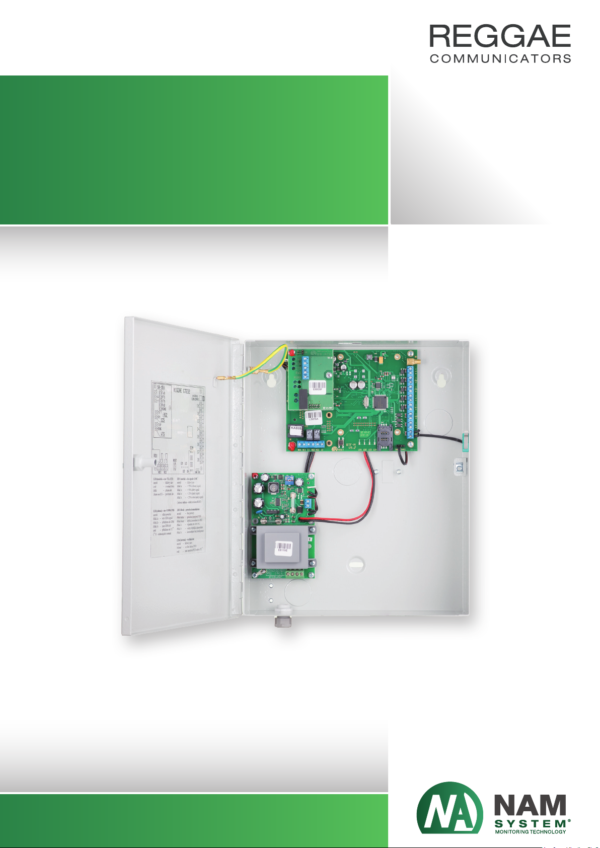
Communicator REGGAE GTbz is a version of communica-
tor REGGAE GT supplemented by a REGGAE power sour-
ce and placed into a case.
Communicator REGGAE GTbz232 is a version of commu-
nicator REGGAE GTbz supplemented by insulated serial
interface module RS232.
Communicator REGGAE GTbz485 is a version of commu-
nicator REGGAE GTbz supplemented by insulated serial
interface module RS422/485.
Communicators REGGAE GTbzxxx receives messages
from FAS panels via serial line through third-party con-
verters. Third-party converters transforms messages
from FAS panels to the format DTX.
Communicators REGGAE eps GTbzxxx have the message
receipting from the FAS panels implemented over the se-
rial line directly without using the third-party converters.
Communicators REGGAE GTbzxxx and REGGAE eps
GTbzxxx do not differentiate in hardware. Communica-
tors REGGAE GTbzxxx and REGGAE eps GTbzxxx do diffe-
rentiate only in installed firmware and configuration.
Further in the manual there are described communica-
tors REGGAE GTbzxxx. The description is common also
for communicators REGGAE eps GTbzxxx.
USER MANUAL REGGAE GT/GTbz
Communicator for GSM (GPRS/SMS) transmission
www.namsystem.com
3

OPERATING CONDITIONS
Devices
REGGAE GT,
REGGAE GTbz,
REGGAE GTbz232
and REGGAE GTbz485
contain a radio transmitter in the GSM band (900/1800
MHz). Their operation is possible under the general
authorization number VO-R/1/04.2014-2 issued by The
Czech Telecommunication Office.
NAM system,a.s. hereby declares that devices
REGGAE GT,
REGGAE GTbz,
REGGAE GTbz232
and REGGAE GTbz485
are in conformity with the essential requirements and
other relevant provisions of Guideline 199/5/ES. Gover-
nment Regulation number 13/2003 Sb. Government Re-
gulation number 616/2006 Sb. and Government Regula-
tion number 481/2012 Sb.
“Declarations of conformity”are issued for communicators
REGGAE GT,
REGGAE GTbz,
REGGAE GTbz232
and REGGAE GTbz485,
these are stored at the device manufacturer.
Operating
REGGAE GT,
REGGAE GTbz,
REGGAE GTbz232
and REGGAE GTbz485
is not possible near medical instruments and other equi-
pment sensitive to electromagnetic field.
The manufacturer shall not be liable for any damages re-
sulting from interventions in the devices
REGGAE GT,
REGGAE GTbz,
REGGAE GTbz232
and REGGAE GTbz485
outside the scope of this installation manual (in particu-
lar method of installation, repair and modifications not
approved by the manufacturer).
Devices connected to
REGGAE GT,
REGGAE GTbz,
REGGAE GTbz232
and REGGAE GTbz485
must comply with the applicable standards (according to
safety EN 60950-1 etc.).
PC of class I can be connected to the
REGGAE GT,
REGGAE GTbz,
REGGAE GTbz232
and REGGAE GTbz485
devices only if it has properly applied its own protection
against accidental contact respectively against electric
shock.
Devices must be installed and operated in dry places and
in the temperature range between
-25 °C to +65 °C.
USER MANUAL REGGAE GT/GTbz
Communicator for GSM (GPRS/SMS) transmission
www.namsystem.com
4

DESCRIPTION OF COMMUNICATORS REGGAEGT/GTBZ/GTBZXXX
Basic technical parameters
REGGAE GT
Rated power REGGAE GT
Environment
Operating temperature range
Dimensions REGGAE GT
Dimensions REGGAE GT232/GT485
10 – 15 VDC; max. 400 mA
class II, inner according to general ČSN EN 50131-1
-25 °C to +65 °C
146 × 114 × 25 mm
146 × 114 × 43 mm
Inputs
Outputs
8× insulated voltage loop
2× changeover relay contact max. 1 A / 30 VDC
(0.3 A / 60 VDC), 0.5 A / 125 VAC
Communication channels serial port RS1 – standard RS232 uninsulated (R×D, T×D, RTS, CTS)
serial port RS2 – TTL (3V) uninsulated (R×D, T×D, RTS, CTS)
– TTL (5V) uninsulated (R×D, T×D)
– standard RS232 insulated (R×D, T×D, RTS, CTS)
– standard RS422/485 insulated
telephone communicator (line PSTN, line AS)
GSM/GPRS communicator (SMS/data channel)
USER MANUAL REGGAE GT/GTbz
Communicator for GSM (GPRS/SMS) transmission
www.namsystem.com
5

GSM/GPRS
Communication band
Output power
GPRS class
Antenna impedance
Connector type
900 / 1800 MHz
2 W / 900 MHz, 1 W / 1800 MHz
8
50 Ω
SMA
Circuit board of REGGAE GT communicator
The circuit board of the REGGAE GT communicator
enables the control and configuration of the complete
mechanism. It includes terminal plates for connecting
voltage insulated inputs, relay outputs and telepho-
ne lines (AS and PSTN). It also contains connectors for
connectingserialports(RS232andTTL)andaconnectorfor
connecting antennas for GSM/GPRS.
REGGAE GTbz/GTbzxxx
Power voltage
Supply current
Medium wattage
Power frequency
Output voltage AUX
Output current AUX
Output fuse AUX
Type of backup battery
Capacity of backup battery
Battery charge current
Operating temperature range
Operating humidity
Protection level
Class of device protection
Dimensions REGGAE GTbz/GTbzxxx
230 VAC ± 10 % (207 VAC to 253 VAC)
max. 0.15 AAC
< 4 W
50 Hz ± 2 Hz
> 13.10 V @ 50 mA; +25 °C
max. 50 mA
return safety fuse
12 V, leaden without maintance hermetically sealed (VRLA/SLA)
1.3 Ah, (2.3 Ah), 4 Ah, 7 Ah
typ. 400 mA, max. 435 mA
-25 °C to +65 °C (except backup battery)
0 – 95 % noncondensing
IP20
class I
301 × 249 × 78 mm (without cable bushing)
USER MANUAL REGGAE GT/GTbz
Communicator for GSM (GPRS/SMS) transmission
www.namsystem.com
6

Powering REGGAE GT communicators
Voltage supply to the REGGAE GT communicator is brou-
ght in through the terminal plate marked „12V“ and
„GND“. Positive field supply is connected to terminal„12V“,
negative to terminal „GND“. The communicator must be
powered by direct current voltage in the range of 10 –
15 VDC. Supply voltage cannot have undulations of more
than 0.2 Vrms. During supply of voltage there cannot be
a faster decline in supply (during normal operation) of
more than 2 V per 1 s (a faster decline will be detected
as a power failure). Medium current consumption of the
communicator is less than 150 mA. During communica-
tion with GSM/GPRS, consumption may rise to up to 400
mA. At this consumption level the power source must be
dimensionalized.
It is possible to power the communicator from the power
source of the AS/FAS panel, as long as the source of the
panel is sufficiently dimensionalized for this additional
consumption.
It is assumed that the voltage supply is protected at the
source, this being with a fast fuse with a current rating
of 630 mA to 1.6 A (F630 mA/250 V to F1.6 A/250 V).
If the power source does not contain this type of fuse at
its output, it is necessary to add this to the power carrier
of the communicator (as close as possible to the power
source output).
Voltage of insulated inputs
The communicator has eight voltage insulated inputs I1
to I8, which switch the supplied voltage to the correct
pole. Each input is implemented by two terminal plates,
on which the polarity of the incoming voltage is marked.
Each input is insulated by an optocoupler. The strength
of insulation between the input terminals I1 to I8 and the
remaining circuits of the REGGAE GT communicator is at
least 1 kVAC (50 Hz). The same strength of insulation is
also mutually between each input.
Voltage at the inputs must be brought in for longer than
the time set in the configuration of the communicator in
order to make sure that inputs are clamped closed (100
ms – fast input or 300 ms – slow input).
The reaction of inputs to inflowing voltage can be inver-
ted in the configuration of the communicator.
The table below shows the reaction of inputs to inflowing
voltage:
USER MANUAL REGGAE GT/GTbz
Communicator for GSM (GPRS/SMS) transmission
www.namsystem.com
Loop status
Closed – alarm
Unspecified status
Released –
idle-circuit
condition
Voltage in loop
+8 V až +40 V
+5 V až +8 V
-40 V až +5 V
Consumption
max. 6 mA
max. 6 mA
7

Diagnostic and conguration of serial portRS1
Serial port RS1 serves to connect the communicator to
a PC with the diagnosis and configuration programme
NAM-manager. The standard of this connector conforms
to the standards RS232 (EIA-232-F, ITU V.28). This serial
port is not insulated from the remaining parts of the co-
mmunicator. A cable reducer, KAB 08, is used for conne-
cting the circuit board of the REGGAE GT communicator
to a PC. Please contact the producer, NAM system, a.s., for
more details of this cable reducer.
Communication serial port RS2
Serial port RS2 serves to transfer news from FAS panels
either through the third-party converters, or in case of
communicators REGGAE eps GTbzxxx, through direct co-
nnection to the serial interface of the FAS panel. Serial
port RS2 is brought out to the pin field CON9. The stan-
dard of the serial port on this connector is TTL (3V). The
serial port at the TTL (3V) level is not insulated from the
remaining parts of the communicator. For connections
with FAS it is necessary to have a module for transfers at
the TTL (3V) level to the circuit board of the REGGAE GT
communicator that is at the standard of the serial port of
the specific FAS interface. The basic type of module for
uninsulated interfaces TTL (5V) and insulated interfaces
RS232, RS422 or RS485 are available from the producer,
NAM system, a.s. The description of the modules for the
insulated serial ports RS232 and RS422/485 can be found
on page 14. The modules ensure insulation of the seri-
al ports RS232/422/485 from the remaining parts of the
communicator. Description and technical parameters
of module TTL (5V) can be found in the actual manual
REGGAE reduction TTL 3V/5V.
Relay outputs
On the circuit board of the REGGAE GT communicator
there are two relay outputs RE1 a RE2 implemented by
two independent relay contact switches.
The terminal plate markings are standard. The mutual
outlet of the switch contact is marked„C“ (Common). The
contact outlet that is clamped close when the status is
idle-circuit is marked „NC“ (Normally-Closed). The con-
tact outlet that is in release when the status is idle-circuit
is marked„NO“ (Normally-Open).
The carrying capacity of each relay output is a maximum
of. 1 A / 30 VDC (respectively 0.3 A / 60 VDC) or 0.5 A / 125
VAC.
USER MANUAL REGGAE GT/GTbz
Communicator for GSM (GPRS/SMS) transmission
www.namsystem.com
8

LD2 (green) – state of GSM/GPRS
(*) technological centre
LD3 (yellow) – breakdown of communicator
(*) only when FAS is activated in configuration
(**) only for communicators GTbz/GTbzxxx
If a number of breakdowns occur at one time, they are
shown in sequence with 1 second gaps between each
breakdown.
LD4 (red) – data transmission
(*) technological centre
RESET button
The RESET button serves to carry out the initiation of the
status of the REGGAE communicator. Pressing the RESET
button for a longer time (longer than 1s) initiates the
restart of the communicator. During this restart, initiation
of all communication channels is carried out. Restart of
the communicator does not cause the deletion of news
and occurences tables and corresponds to the turning on
of supply to the communicator.
Pressing the RESET button for a short time starts the in-
dication of the signal strength of GSM/GPRS on the blue
LED LD1. This indication is active for 1 minute. After this
time, the blue LED LD1 will again indicate the status of
the telephone communication wilth the AS.
Indication of the status of the communicator - LED
lights
LED LD1 to LD4 on the circuit board of the REGGAE GT
communicator serve to indicate the present state of the
REGGAE communicator.
The meaning of the LED indication lights are as follows:
LD1 (blue) – state of telephone communication
with AS
LD1 (blue) – strength of GSM/GPRS signal
(1 minute after a short press of the RESET button)
LD1 (blue)
Not shining
Shining
Flashing
Turns off for 0.5 s
Meaning
Idle-circuit state
Line is being answered
or PSTN disconnected
Receiving data
Confirmation of data receipt
USER MANUAL REGGAE GT/GTbz
Communicator for GSM (GPRS/SMS) transmission
www.namsystem.com
LD1 (blue)
Not shining
Flashes 1×
Flashes 2×
Flashes 3×
Flashes 5×
Meaning
Idle-circuit state
Excellent signal (>75 %)
Good signal (>50 %)
Bad signal (>25 %)
Very bad signal (<25 %)
LD2 (green)
Not shining
Flashes 1×
Flashes 2×
Flashing quickly
Shining
Meaning
Serious breakdown of GSM/GPRS
No GSM signal
Logged in GSM
Scanning of GSM network
Logged in TC (*)
LD2 (green)
Not shining
Short flashes
Long flashes (*)
Flashes 2× (**)
Flashes 3× (**)
Flashes 5×
Meaning
No breakdown
Breakdown (disconnected) PSTN
Communication problem at RS2
Outage of 230 VAC network
Defective/missing accumulator
Communicator without
configuration
LD4 (red)
Not shining
Flashing
Shining
Meaning
Idle-circuit state
Transmitting data to ARC
Not connected to ARC or to TC (*)
9

Antenna connector - GSM/GPRS
For connecting antennas for GSM/GPRS there is a conne-
ctor of type SMA on the circuit board of the REGGAE GT
communicator. Any antenna that satisfies the necessary
operation conditions in the range GSM/GPRS 900/1800
MHz with impedance 50 Ω can be used.
Antennas must be adapted for both indoor and outdoor
usage.
Antennas with a magnetic base are most commonly
used, and these can be fixed to the outer surface of the
panel or REGGAE communicator cases.
Telephone unit of communicator
The telephone unit of the circuit board of the REGGAE
GT communicator is able to communicate with the AS
panel in all common pulsation and DTMF formats. Supp-
orted formats are 4+2, Ademco Point ID (Contact ID),
communication speed 10, 20 or 40 bps with handshake
1400 Hz, 2300 Hz or multi-tone.
Dialled telephone numbers can be set up as pulsation or
DTMF at the AS panel.
The telephone unit of the REGGAE GT communicator can
generate the dialling tone of the line for the AS panel
(from the FW 6.xx communicators). This function is optio-
nal in the communicator configuration.
The terminal plates marked „T1“ and „T2“ are used for
connecting telephone lines from the AS panel. If the AS
panel has to communicate directly with the ARC, the
PSTN telephone line must be connected to the terminal
plates marked „TIP“ and„RING“. Also, if the communicator
has to send news and occurences on the ARC channel,
the VTS telephone line must be connected to the termi-
nal plates marked„TIP“ and„RING“.
Tampers on the communicator
The connectors TMP1 TMP2 on the circuit board of the
REGGAE GT communicator are used to connect up to
two tampers. The connector has four pins. The two pins
on the left side marked TMP1 are used to connect the first
tamper. The two pins on the right side marked TMP2 are
used to connect the second tamper.
For both tampers it is assumed that contact will be
released immediately if they are disrupted.
The tamper on the box of REGGAE GTbz/GTbzxxx com-
municators is standardly connected as TMP1. TMP2 is
normally used for power outage detection.
USER MANUAL REGGAE GT/GTbz
Communicator for GSM (GPRS/SMS) transmission
www.namsystem.com
10

Power source circuit board - REGGAE
REGGAE GTbz/GTbzxxx communicators are powered by
alternating supply grid 230 V / 50 Hz. The power source
circuit board is used to create direct current power vol-
tage 13.8 V for the REGGAE GT communicator. The out-
put of direct current voltage from the power source cir-
cuit board is backed up by a VRLA accumulator 12 V.
Powering the REGGAEGTbz/GTbzxxx communicators
Direct current power voltage 230 V is brought into the
communicator through the terminal plates marked „L“,
„N“ and „PE“. The maximum power consumption of the
communicator from the alternating current supply grid
is less than 150 mA.
Back-up accumulator
The back-up accumulator is connected to the red and
black conductors of the power source circuit board (with
end fasteners). The power source circuit board ensures
the operating state of the accumulator – this means char-
ging and connection/disconnection of the accumulator
from the direct current output from the power source
circuit board. The maximum charging supply of the accu-
mulator is limited to 435 mA. During operation of the
power source circuit board at alternating grid 230 V, the
accumulator is constantly charged at a voltage of 13.8 V.
The power source is designed to serve VRLA accumula-
tors 12 V with a capacity in the range of 1.2 to 7.5 Ah.
The power source circuit board ensures automatic dis-
connection of the accumulator in cases where its open
circuit voltage falls below 8.9 V during operation of the
communicator by the accumulator (this means at times
of loss of alternating current supply voltage 230 V). Even
during the absence of alternating current supply voltage
230 V it is possible to put the communicator into opera-
tion by connecting an accumulator with an open circuit
voltage of more than 11.5 V.
Supply output AUX
Supply of output AUX is achieved by using the terminal
plates marked„AUX“ and „GND“. This output is meant for
possible supply of the circuit of the voltage insulated in-
puts I1 to I7 on the circuit board of the REGGAE GT com-
municator. During operation of the communicator using
the alternating grid 230 V the AUX output allows direct
current voltage of 13.1 – 13.8 V. During operation of the
communicator using the back-up accumulator, voltage
of the AUX output may fall to a value of 8.5 V. The maxi-
mum power consumption of the AUX output is 50 mA.
The AUX output is not insulated from the remaining parts
of the communicator and so its usage for supplying any
of the inputs I1 to I7 leads to the breach of the insulation
of the inputs involved.
The AUX output is protected from short-circuiting by a
return safety fuse. This guarantees the limiting of power
coming from the short-circuit of the output to less than
100 mA.
USER MANUAL REGGAE GT/GTbz
Communicator for GSM (GPRS/SMS) transmission
www.namsystem.com
11

LED indicators on the power source circuit board
Two LED indicators are located on the power source
circuit board.
When the green LED light marked „AC“ shines this indi-
cates the presence of alternating current voltage at the
input 230 V.
When the green LED light marked„AKU“ shines, this indi-
cates that the power source is ready to charge the circuit
board of the REGGAE GT communicator from the accu-
mulator and also from the grid 230 VAC. The LED light
„AKU“ shines even when the accumulator is not connec-
ted as long as alternating current power voltage 230 V is
connected. The LED light„AKU“ does not indicate the sta-
tus of the accumulator. Diagnosis of the state of the accu-
mulator is carried out and indicated on the circuit board
of the REGGAE GT communicator.
During operation of the REGGAE GTbz/GTbzxxx commu-
nicator by the back-up accumulator, the LED light „AKU“
will shine when the accumulator is connected to the
power source circuit board of the REGGAE GT commu-
nicator. If the circuit source disconnects the accumulator
due to its low open circuit voltage (< 8.9 V), the LED light
„AKU“ will turn off.
Safety fuses
Two safety fuses are located on the power source circu-
it board. Safety fuse T800mA serves to protect output
transformators at source in the case of serious violations
of the output circuit source.
Safety fuse F1.6A protects the circuit source against the
reserval of poles on the accumulator. It also protects the
accumulator in the case of serious violations of the out-
put circuit source.
Operating time of REGGAE GT/GTbz/GTbzxxx com-
municators using the back-up accumulator
The table below shows the approximate times that RE-
GGAE GT, REGGAE GTbz, REGGAE GTbz232 a REGGAE
GTbz485 communicators are capable of operating for
when using back-up accumulators of various capacities.
The times shown in the table are for standard operation
of the communicators (e.g.10 telephone line communi-
cations daily with the AS including news sent on the ARC
channel GPRS). Operation of the communicator is expec-
ted up to a voltage of 9 V on the accumulators terminal.
The operating times for new accumulators shown in the
table are valid when the capacity of the accumulator is
100 % of its voltage rating.
The operating times shown for older accumulators are
valid when the capacity of the accumulator is 80 % of
its voltage rating. Standard VRLA accumulators usually
reach a capacity of 80 % of voltage rating after approxi-
mately 2 years operation at room temperature (20 °C to
30 °C), according to information from the producers of
the accumulators.
USER MANUAL REGGAE GT/GTbz
Communicator for GSM (GPRS/SMS) transmission
www.namsystem.com
12
Capacity
accumulator
1.3 Ah
4 Ah
7 Ah
Operating time
new accumulator
16 hours
75 hours
120 hours
Operating time
older accumulator
13 hours
60 hours (2,5 days)
96 hours (4 days)

Modules RS422/485 and RS232
Modules serve to transfer data between FAS interface
and REGGAE communicators. The standard of input and
output modules RS422/485 fully conform to standards
ANSI RS-485 and ISO 8482:1987(E). The standard of input
and output module RS232 fully conforms to standards
EIA-232-F and ITU V.28.
Modules RS422/485 and RS232 ensure the insulation of
the communication channel RS2 from the remaining parts
of the communicator. The strength of insulation between
the communication channel and the remaining circuits of
the communicator is a minimum of 1 kVAC (50 Hz).
Connecting modules RS422/485
The meanings of each terminal on the circuit board of the
module RS485 in relation to the REGGAE GTbz485 com-
municator are as follows:
The length of the connecting cable for the communica-
tion serial port RS422/485 may be a maximum of 1000m
taking into account possible disturbances and overall ca-
pacity. The recommended type of cable is UTP. If a STP
cable is used, the shielded cable is connected to terminal
„RGND“.
Short-circuit connectors J1 to J5 are configurated by mo-
dule RS422/485 according to requested type of interface.
Closed connector J1 is connected to end resistor 120 Ω
between inputs A-B. Closed connectors J3 and J4 conne-
ct inputs A/B with outputs Y/Z for interface RS485. Clo-
sed pins 1 and 2 of connector J5 set a positive idle-circuit
level at input A/B. Closed pins 2 and 3 of connector J5
set a negative idle-circuit level at input A/B. To ensure the
correct function setting of the idle-circuit level using co-
nnector J5, connector J2 must be closed.For configurati-
on of the module at interface RS485, it is usual to use all
connectors. For interface RS422 it is usual to close only
connector J1.
Connecting modules RS232
The meanings of each terminal on the circuit board of the
module RS232 in relation to the REGGAE GTbz232 com-
municator are as follows:
The length of the connecting cable for the communica-
tion serial port RS232 may be a maximum of 15 m taking
into account possible disturbances and overall capacity.
The overall capacity for each signal conductor again-
st grounding of communication lines cannot exceed
approx. 2000pF.
Terminal
Y
Z
A
B
RGND
Meaning
Data output Y
Data output Z
Data input A
Data input B
Signal - Reverse ground
Terminal
T×D
RTS
CTS
R×D
RGND
Meaning
Data output
RTS output
CTS input
Data input
Signal – Reverse ground
USER MANUAL REGGAE GT/GTbz
Communicator for GSM (GPRS/SMS) transmission
www.namsystem.com
13

INSTALLATION OF THE COMMUNICA-
TOR REGGAE GT/GTBZ/GTBZXXX
Location requirements for
communicator REGGAE GT
Handle the REGGAE GT communicator circuit board with
care to avoid damaging (breaking) ferrite inductors, par-
ticularly on the underside of the circuit board.
Fasten the circuit board into the panel box or into ano-
ther device with four self-adhesive distance columns
(included in the packaging of the REGGAE GT communi-
cator). When placing the circuit board of the communi-
cator onto the metal base, secure the space underneath
the bottom side. Check, if any surface inequalities are not
too close to the board components. Minimum distance
between components and surface must be more than
3 mm.
Placement requirements for
communicator REGGAEGTbz/GTbzxxx
In the rear wall of the metal box of the communicator RE-
GGAE GTbz/GTbzxxx there are holes prepared for pulling
through all the cabling. Holes are covered during produc-
tion. Remove the metal disc covers from holes required
and pull the cabling through into the of communicator
case.
Fix the communicator case onto the wall using three
screws, for which there are three holes designated on
the back wall of the metal case. Two holes in the upper
corners of the case are adapted for hanging up the case.
Screw a screw into the third hole in the middle of the
bottom part of the case in order to protect the case from
slipping from its hung position.
After installing the metal case on the wall, always check
the strength of fixation in order to prevent later injury or
property damage caused by the communicator box fa-
lling down!
Connecting the GSM/GPRS antenna
GSM/GPRS antenna must be placed outside the metal
case where the communicator is placed, otherwise pr-
oper communication will not be ensured.
Coaxial antenna cables designed for interiors are thin
and flexible. It is possible to connect such antenna types
directly to the SMA connector of the communicator wi-
thout major problems. Always make sure to avoid bre-
akage of the coaxial cable, respectively sharp bends on
a small radius.
It is appropriate to connect external antenna and com-
municator with quality coaxial cable (impedance 50 Ω),
e.g. type RLH1000. Such cable types cannot be directly
connected to the SMA connector of the communicator.
Use short cable reduction with corresponding connec-
tors in order to connect inflexible coaxial cables to the
connector of the communicator (e.g. SMA <--> N).
Connecting the inputs
Connect the insulated voltage inputs. In the inputs de-
scription and in the communicator configuration you will
find detailed information about input functions.
Connecting the outputs
Connect the relay outputs. In the relay outputs descripti-
on and in the communicator configuration you will find
detailed information about technical parameters and
about output functions.
Connecting the serial port RS2
Detailed information about connecting the terminal pla-
te and about technical parameters of serial port modules
can be found in the module RS422/485 and RS232 de-
scriptions.
USER MANUAL REGGAE GT/GTbz
Communicator for GSM (GPRS/SMS) transmission
www.namsystem.com
14

Connect the panel AS telephone line RING/TIP onto the
terminal plates marked “R1”and“T1” on the communica-
tor REGGAE GT circuit board.
For proper functioning of telephone communication be-
tween AS and communicator, connection to PSTN is not
necessary. When PSTN line is not connected, communi-
cator automatically transfers to the simulated line regime
on the AS side. If the line is not answered on the side of
the AS in the simulated line regime, there is voltage of
approx. 23 V on the terminal plates “R1” and “T1” of the
communicator REGGAE GT circuit board.
If you want to retain the option of communication be-
tween AS panel and ARC, then connect telephone line
PSTN onto the terminal plates marked “RING” and “TIP”
on the communicator REGGAE GT circuit board.
Connecting the telephone line
In case of disturbance on the telephone line PSTN (vol-
tage drop on the line) the line is automatically disconne-
cted to avoid communication interference between AS
and communicator.
In order to have a functionally connected telephone
device on terminal plates R1/T1 of the AS panel, there
must be an available connection to the PSTN line for the
communicator. The circuit board of the communicator
REGGAE GT desk is not capable of the GSM gateway func-
tion.
Detailed information about technical parameters and
about the functions of telephone communication can
be found in the description of the telephone unit of the
communicator and in the description of the communica-
tor configuration.
USER MANUAL REGGAE GT/GTbz
Communicator for GSM (GPRS/SMS) transmission
www.namsystem.com
15

Power supply connection to the
communicator REGGAE GT
Connect power supply 10 – 15 V to the communicator
REGGAE GT. Conduction of the supply voltage wires,
which is used for the communicator, must be secured
against possible circuiting sabotage. Therefore it is
inappropriate to use the same power supply as for the
sensors, where the short circuit, in this usually relatively
easily accessible charge, causes communicator disfunc-
tion. It is necessary that on the terminal plates of the
communicator, parameters listed in the description of
powering the communicator REGGAE GT are respected.
Detailed information of power supply technical para-
meters can be found in the description of powering the
communicator REGGAE GT.
Power supply connection to the communicator
REGGAE GTbz/GTbzxxx
Connect power supply 230 VAC of the communicator RE-
GGAE GTbz/GTbzxxx to the terminal plates “PE”, “N” and
“L” on the power source circuit board. Communicator
must always be connected to the protective conduc-
tor of the grid 230 V. Carry out connection to the grid
230 V by using a flexble supply line with plug or by fi-
xed supply. Flexible supply lines must lead through
bushing. In the bushing this must be well fixed against
pulling out. Bushing also protects the supply line again-
st abrasion of the insulation by sharp edges of the case.
The network plug of the exible supply line serves as
a means for disconnecting the communicator from
the grid. The power socket must then be close to the
device and must be easily accessible. Overcurrent
protection must be part of the installation of the soc-
ket. If necessary, the flexible supply line with plug can be
replaced by wired connection. Wired connection must
only be performed by a person with a valid certicate
for such activity! When connecting the wired connec-
tion, there must be an appropriate disconnecting me-
dium implemented as part of the electrical installati-
on in the building. The nominal value of superposed
overcurrent protective element can be maximum 16
A. Detailed information about technical parameters of
supply voltage can be found in the description of the po-
wer supply of the communicator REGGAE GTbz/GTbzxxx.
Conguration and testing the
communicator
Configure the communicator locally on PC by using pro-
gramme NAM manager (connection via serial port), or
remotely again by using programme NAM manager. The
process of configuration is listed in the user manual of
the programme NAM manager.
Test all of the installed communication channels (co-
mmunication with AS/FAS, communication with ARC
and GSM/GPRS). Then also test functions of all installed
inputs and outputs. For testing preferably use a serial
port connection to PC and programme NAM manager.
Detailed information about testing options are listed in
the user manual of the programme NAM manager (in the
description of diagnostics of the communicator). For cur-
sory communicator function testing, status indication via
LED LD1 to LD4 can be used (see communicator status
indication via LED).
USER MANUAL REGGAE GT/GTbz
Communicator for GSM (GPRS/SMS) transmission
www.namsystem.com
16

MESSAGE RECEPTION FROM REGGAE GT/GTBZ COMMUNICATORS
USER MANUAL REGGAE GT/GTbz
Communicator for GSM (GPRS/SMS) transmission
We use a NSG Receiver for receiving messages from REGGAE communicators. The receiver can communicate
with ARC via TCP/IP or via serial port (optional accessories) by universal format Sur-Gard. This format is supported by
almost all common software for ARC.
Basic parameters of the NSG Receiver
• Main channel for communication with NSG: Encrypted connection via internet
• Backup channel for communication with NSG: GSM/GPRS
• Output Sur-Guard: Serial (assisted by MOXA convertor) or via TCP/IP
• Number of connectable devices (REGGAE): 0xFFF = 4095
• Formats of output codes: 4+2, Contact ID, BSD
The table of occurrence codes from the REGGAE communicator can be found in the separate manual for the
NSG Receiver, version 1.60.
www.namsystem.com
PRODUCER:
NAM system, a.s.
U Pošty 1163/13
735 64 Havířov - Prostřední Suchá
Czech Republic
Tel.: (+420) 596 531 140
E-mail: [email protected]
www.nam.cz; www.onisystem.cz
Version: 6/2016
17
This manual suits for next models
6
Table of contents
Other NAM system Cell Phone manuals