ENGLISH
1.0 GENERAL CHARACTERISTICS
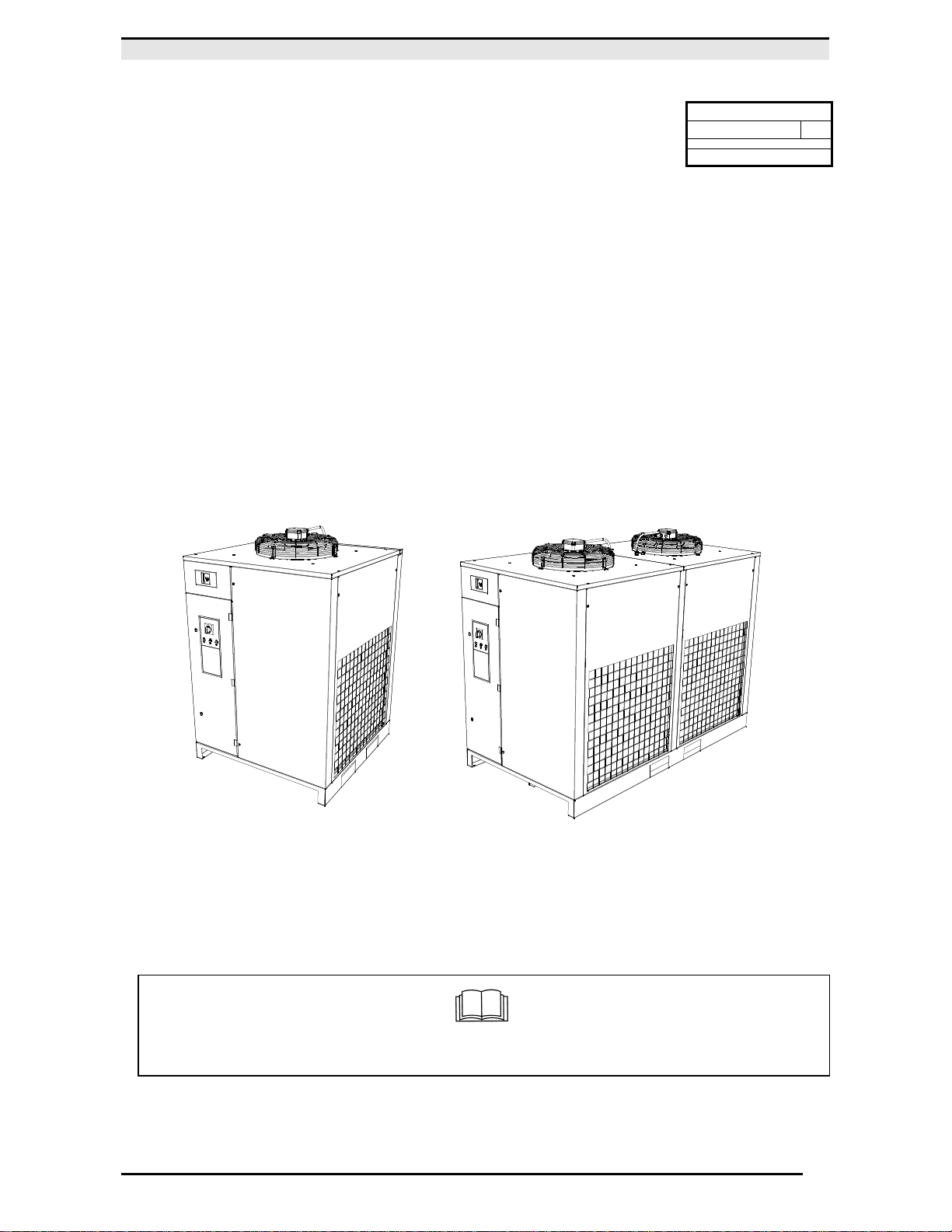
The dryer is a chilling machine with direct expansion heat exchanger and dry evaporator.
The air to be dried is sent to the heat exchanger in which the water vapor present is condensed: the condensate gathers
in the separator and is discharged outside through an electronic level sensing drain..
2.0 INTENDED USE
The dryer has been designed and built to dry compressed air for industrial use. The dryer cannot be used in premises
where there is a risk of fire or explosion or where work is carried out which releases substances into the environment
which are dangerous with regard to safety (for example: solvents, inflammable vapours, alcohol, etc.).
In particular the appliance cannot be used to produce air to be breathed by humans or used on direct contact with
foodstuffs. These uses are only allowed if the compressed air is additionally treated by means of a suitable purification
system
(Consult the manufacturer for these special uses.)
This appliance must be used only for the purpose for which it was specifically designed. All other uses are to be
considered incorrect and therefore unreasonable. The Manufacturer cannot be held responsible for any damage resulting
from improper, incorrect, or unreasonable use.
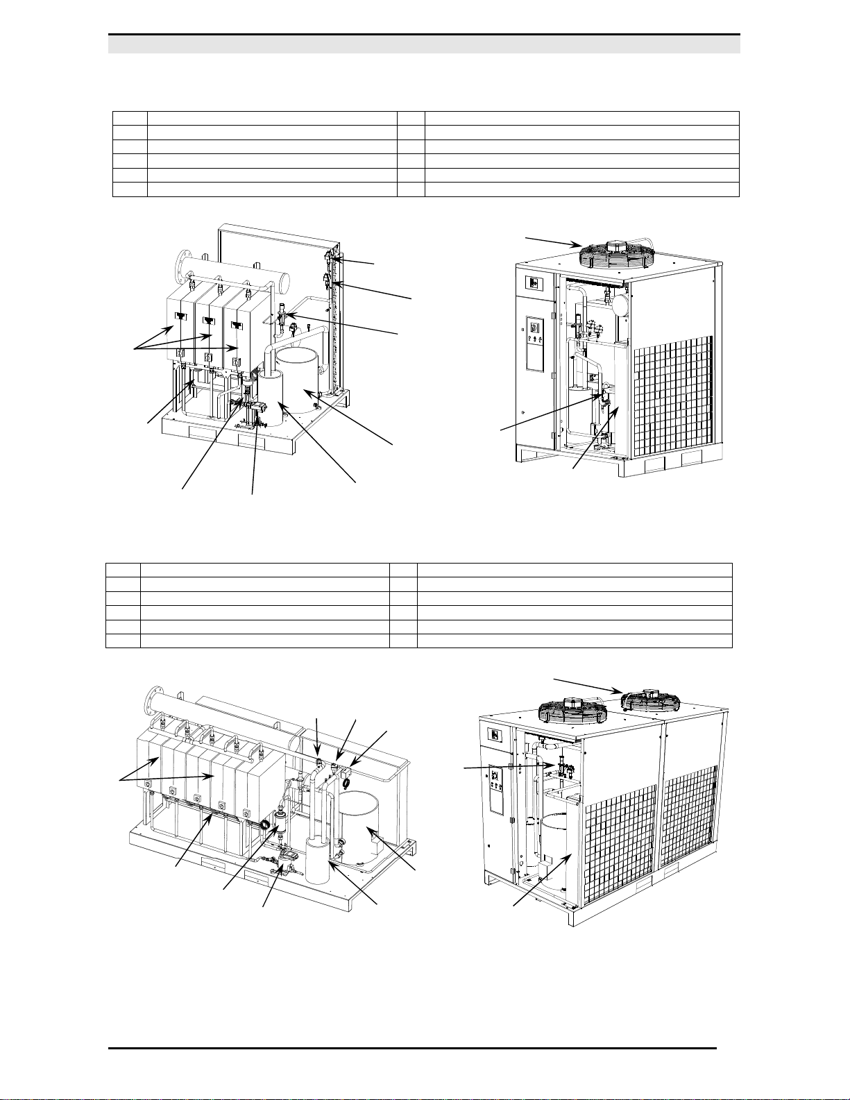
3.0 OPERATION
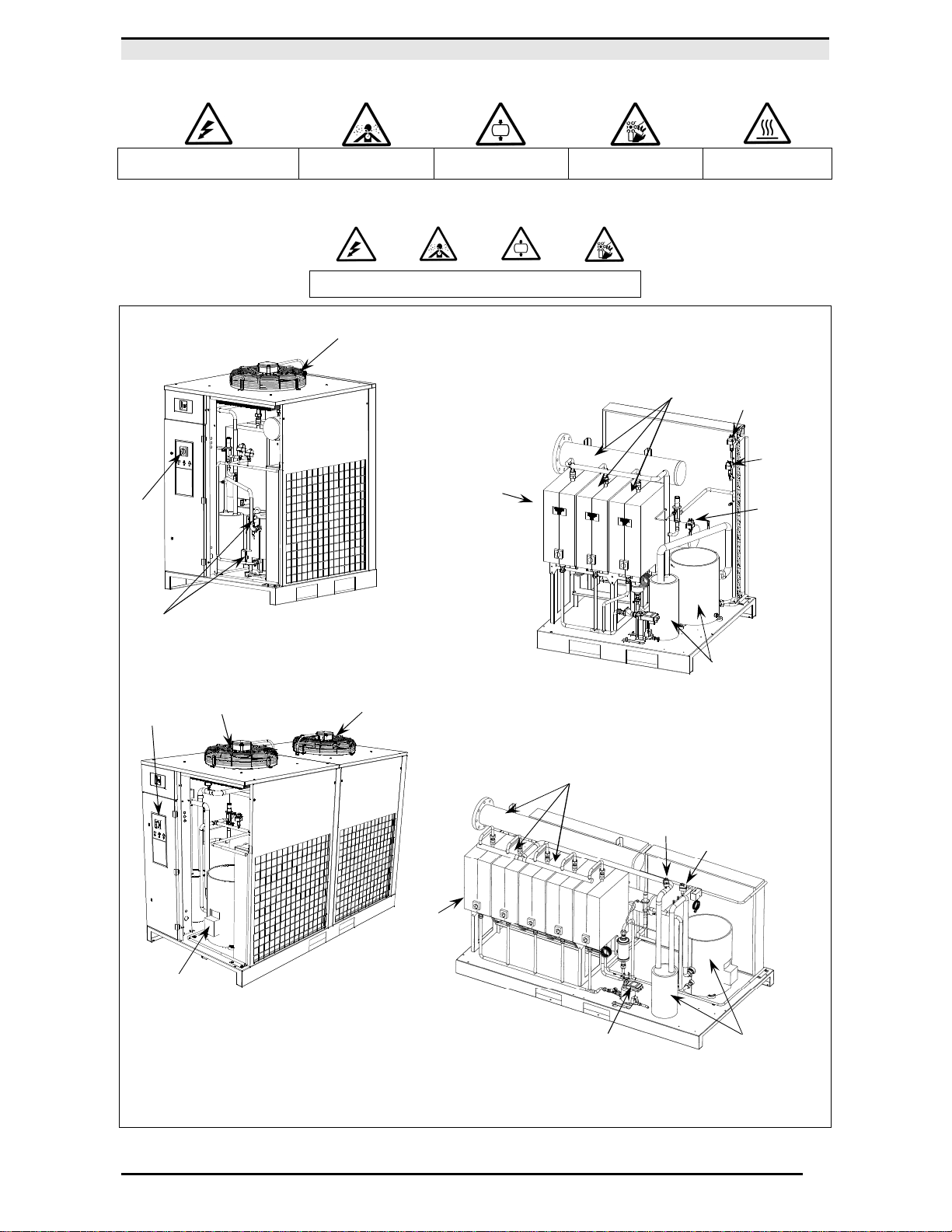
The hot gaseous refrigerant leaves the evaporator (4) and enters the refrigeration compressor (1) where it is compressed
and pumped into the condenser (2). With the aid of a cooling fan (3) the refrigerant is condensed into a liquid. The
condensed liquid refrigerant then passes through a filter/dryer (8) to remove any residual moisture. A capillary tube (7) is
used as an expansion device before the refrigerant re-enters the evaporator (4). The expansion and evaporation of the
refrigerant produces a cooling effect. Due to the heat exchange with the compressed air passing through the heat
exchanger, the air temperature is reduced causing water vapour to condense out of the air stream. The water is
removed in a water separator (5) so that it can be evacuated though the automatic level drain (13). The now gaseous
refrigerant is returned to the compressor (1) where the cycle repeats.
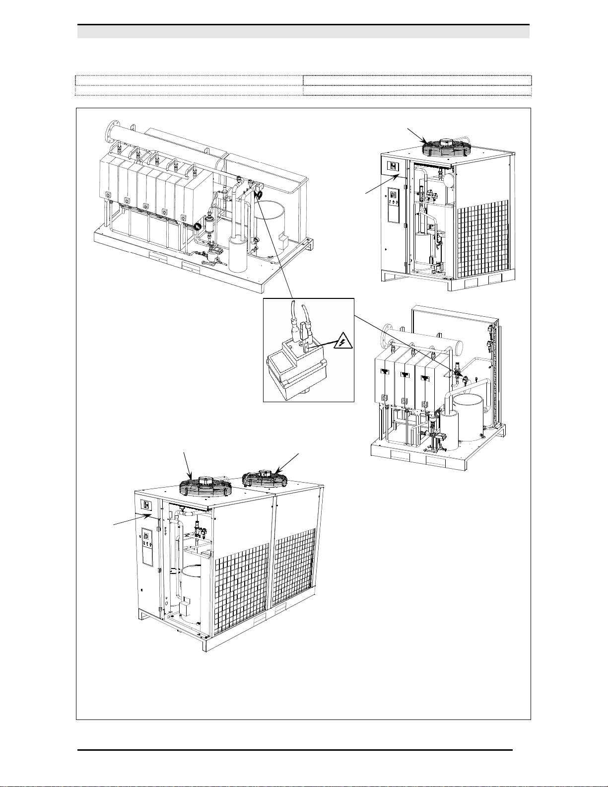
The circuit is equipped with a hot gas bypass (HGBP) system for the refrigerant which adjusts the available refrigerating
capacity to the actual cooling load. This is achieved by injecting hot gas under the control of the HGBP valve (9) to
maintain a constant refrigerant pressure in the evaporator. With this control the of the refrigeration pressure the
temperature never decreases below (32°F / 0°C).
DRYER FLOW DIAGRAM
1) REFRIGERANT COMPRESSOR
) FAN CONTROL PRESSURE SWITCH
5) DEMISTER CONDENSATE SEPARATOR 13) MAX PRESSURE SWITCH
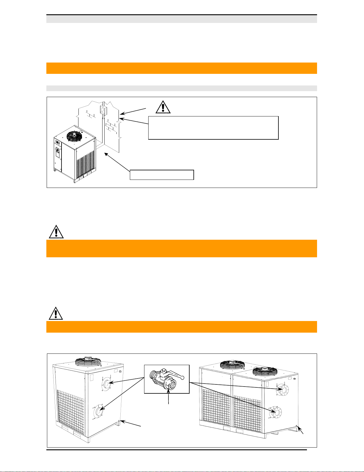
4.0 GENERAL SAFETY STANDARD
The appliance may be used only by specially trained and authorized personnel.
Any tampering with the machine or alterations not approved beforehand by the Manufacturer relieve the latter of
responsibility for any damage resulting from the above actions.
The removal of or tampering with the safety devices constitutes a violation of the European Standards on safety.
ALL WORK ON THE ELECTRONICS AND REFRIGERANT CIRCUIT, HOWEVER SLIGHT, MUST BE CARRIED OUT BY PROFESSIONALLY
SKILLED PERSONNEL.
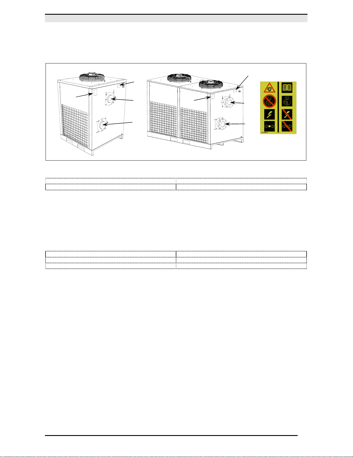
AIR OUTLET
CONDENSA
D