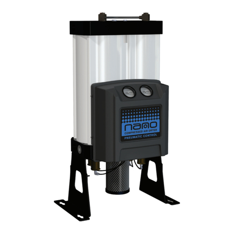
NANO D1-C Manual

Maintenance & Service Manual
heatless desiccant air dryer
revision: 2021-307 document: 17-100-0691
© 2021 Nano Purication Solutions Ltd.
www.n-psi.co.uk

Experience. Customer. Service.
about us
Experience.
Our team is comprised of and supported by individuals spanning
all disciplines from research & development, engineering &
manufacturing, marketing & sales and service & support. Our
backgrounds are in air and gas purication and our experience
in this eld spans a wide range of industries. We combine this
knowledge and experience to ensure our products and services are
designed and provided to meet the objectives and expectations
of you - our Customer.
At nano we recognise that world-class customer service is the
most important component to any successful business. Your
business needs to exceed your customers’ expectations to
stand out from your competitors and our service must positively
impact your business so you can be successful in doing so. Our
commitment is simple… we will stand behind our products and
ensure that our customer service is unrivaled in the industry.
Customer.
We recognise that our Customers are not only our valuable
distribution partners who sell and support our products or the
machine builders who depend on them as protection for their
equipment. They are the contractors who install them, the
manufacturers who use them in their processes and the service
people who maintain them. At nano we have developed our
products, packaging and support materials to ensure they exceed
all of our Customers’ expectations.
Service.

3
section description page
1. support details 4
2. general information
5
2.1 document introduction
2.2 warranty guidelines
2.3 general safety
2.4 intended use of the product
3. technical specications
6
3.1 ow rates
3.2 correction factors
3.3 product dimensions 7
4. product overview 8
4.1 typical system layout 9
4.2 remote start/stop control 10
4.3 start-up procedure 11
4.4 shutdown procedure
4.5 control panel displays 12
5. maintenance
13
5.1 cleaning
5.2 daily checks
5.3 service guidelines
5.4 service schedule and breakdown 14
5.5 service kits and spares 15
6trouble shooting 16
7process and instrumentation diagram 17
7.1 wiring diagram 18
notes 19

4
heatless desiccant air dryers
D1-C
1. manufacturers details and support
nano-purification solutions ltd. (Manufacturer)
address: Dukesway
Team Valley Trading Estate Gateshead
NE11 0PZ
United Kingdom
telephone: +44 (0) 191 497 7700
internet: www.n-psi.co.uk
email: [email protected]
usa - nano-purification solutions inc.
address: 5509 David Cox Road
Charlotte, NC 28269
USA
telephone: +1 (704) 897-2182
internet: www.n-psi.com
email [email protected]
canada - nano-purification solutions inc.
address 7 Petrie Street
St. Catharines,
Ontario
L2P 3J6
Canada
telephone: +1 (905) 684-626
internet: www.n-psi.com
email: [email protected]
germany - nano-purification solutions inc.
Mommenpesch, 46
D-47839 Krefeld
Germany
telephone: +49 2151 4828 418
internet: www.n-psi.de
email: [email protected]

5
heatless desiccant air dryers
D1-C
5
2. general information
This manual is copyrighted, all rights reserved. It may not, in whole or in part, be copied, photocopied, reproduced, translated, or reduced
to any electronic medium or machine readable form without prior consent in writing. It may not be distributed through the internet or
computer bulletin board systems without prior consent.
2.1 document introduction
This manual provides factory prescribed maintenance procedures for the heatless desiccant air dryers. The procedures illustrated in this
document are only to be performed by authorized personnel. For further information regarding the procedures outlined in this document
contact the manufacturer before proceeding.
2.2 general safety
No modications must be made to the product. Any modications may reduce the operational safety of the product and invalidate the
manufacturer’s warranty. This could potentially result in damage to the product and serious personal injury.
For your own safety, when carrying out work on this product, all relevant national safety regulations must be complied with relating to
pressurized and electrical systems.
Only authorized, competent and trained personnel are permitted to work on this product. This user guide is intended solely for such
personnel and is to be used only as a reference; it should not be used to replace conventional training.
2.3 packaging
All products are securely packaged in a specically designed wooden packing box. The dryer will be held in a horizontal position by
wooden struts; using straps to secure the product to the box base. The box top cover can be removed by removing the 4 xing screws
and lifting off in one piece.
2.4 intended use of the product
The heatless desiccant air dryers is exclusively intended for the treatment of compressed air, which is free from bulk water, oil and
solid matter constituents.
The product should be located within a building and protected from extreme conditions and weather. The heatless desiccant air dryers
must be operated only in accordance with the data on the rating plate. Any operations that do not comply with those stated on the
product rating label will render the warranty void
NOTES: highlight important sections of
information where particular care and
attention should be paid.
CAUTIONS: indicate any situation or
operation that may result in potential
damage to the product, injury to the user,
or render the product unsafe.
annotations

6
D3
heatless desiccant air dryer
2.5 service schedule and breakdown
service year 1
(12 mths)
year 2
(24 mths)
year 3
(36 mths)
year 4
(48 mths)
year 5
(60 mths)
year 6
(72 mths)
year 7
(84 mths)
year 8
(96 mths)
Aüüüüüüüü
Büüüü
Cü ü
E
(ES MODELS ONLY) üüüüüüüü
Service A - Every 1 year (12 months)
Replace external exhaust silencer/mufer element(s)
Service B - Every 2 year (24 months)
Replace integrated lters
Replace exhaust valves
Replace inlet valves
Replace outlet valve seals
Replace top manifold gasket seals
Service C - Every 4 year (48 months)
Replace control valves [inc. solenoid coils]
Service E - Every 1 year (12 months)
Calibrate dew-point sensor
(Applicable to ES models only)
When contacting your service provider be sure to provide the part number and serial number of your dryer, this can be found
on the rating plate.

7
D3
heatless desiccant air dryer
2.7 service kits and spares
model (example) kit number description
Service A - Replace external exhaust silencers / mufers
40-110-G-0000- BSP - 130 BSPT exhaust silencer element
40-110-A-0000- NPT - 130 NPT exhaust silencer element
Service B - Desiccant replacement kit
40-110-T-2110- NDA-110 (x2)
loose ll desiccant and gaskets
40-110-T-2120- NDA-120 (x2)
40-110-T-2130- NDA-130 (x2)
40-110-T-3130 NDA-130 (x3)
40-110-T-4130- NDA-130 (x4)
40-110-T-6120- NDA-120 (x6)
40-110-T-6130- NDA-130 (x6)
40-110-S-2110- NDK-110 (x2)
desiccant cartridge and gaskets
40-110-S-2120- NDK-120 (x2)
40-110-S-2130- NDK-130 (x2)
40-110-S-3130- NDK-130 (x3)
40-110-S-4130- NDK-130 (x4)
40-110-S-6120- NDK-120 (x6)
40-110-S-6130- NDK-130 (x3)
40-110-L-2110- NDA-110-LDP (x2)
low point desiccant (LDP) cartridge and gaskets
40-110-L-2120- NDA-120-LDP (x2)
40-110-L-2130- NDA-130-LDP (x2)
40-110-L-3130- NDA-130-LDP (x3)
40-110-L-4130- NDA-130-LDP (x4)
40-110-L-6120- NDA-120-LDP (x6)
40-110-L-6130- NDA-130-LDP (x6)
40-110-M-2110- NDK-110-LDP (x2)
loose ll low dew point (LDP) desiccant and gaskets
40-110-M-2120- NDK-120-LDP (x2)
40-110-M-2130- NDK-130-LDP (x2)
40-110-M-3130- NDK-130-LDP (x3)
40-110-M-4130- NDK-130-LDP (x4)
40-110-M-6120- NDK-120-LDP (x6)
40-110-M-6130- NDK-130-LDP (x6)

8
D3
heatless desiccant air dryer
model (example) kit number description
Service C - Valve servicing (NOTE; you may require more than one kit)
all models EVK-6130 2 internal exhaust valves
all models IVK-6130 2 internal inlet valves
all models OVK-6130 2 internal outlet valves
40--O-0000-QPVKO-6130-024 24v pilot normally open operation valves
40--O-0000-SPVKO-6130-240 240v pilot normally open operation valves
40--O-0000-RPVKO-6130-110 110v pilot normally open operation valves
40--C-0000-QPVKC-6130-024 24v pilot normally closed operation valves
40--C-0000-SPVKC-6130-240 240v pilot normally closed operation valves
40--C-0000-RPVKC-6130-110 110v pilot normally closed operation valves
Service C - Overhall kits
40--O-0000-QNOKO-6130-024 PVKO-6130-024, EVK-6130, IVK-6130 & OVK-6130
40--O-0000-SNOKO-6130-240 PVKO-6130-240, EVK-6130, IVK-6130 & OVK-6130
40--O-0000-RNOKO-6130-110 PVKO-6130-110, EVK-6130, IVK-6130 & OVK-6130
40--C-0000-QNOKC-6130-024 PVKC-6130-024, EVK-6130, IVK-6130 & OVK-6130
40--C-0000-SNOKC-6130-240 PVKC-6130-240, EVK-6130, IVK-6130 & OVK-6130
40--C-0000-RNOKC-6130-110 PVKC-6130-110, EVK-6130, IVK-6130 & OVK-6130
Service D - Dew point sensors (optional)
40--S-0000-E
40--T-0000-ENSK-130 Dew point sensor calibration for standard -40C (-40F)
40--L-0000-E
40--M-0000-ENSK-130-LDP Dew point sensor calibration for standard -70C (-95F)
Energy saving upgrade kits
40--S-0000-
40--T-0000- ESU-130 Energy saving upgrade kit; Dewpoint sensor and accessories
40--L-0000-
40--M-0000- ESU-130-LDP Energy saving upgrade kit; Low-dewpoint sensor and accessories

9
D3
heatless desiccant air dryer
2.8 shutdown procedure
Isolate unit from compressed air system.
The unit will still be pressurized
Ensure the unit is fully depressurized and isolated
To fully depressurize, following the steps below;
• Once isolated from the compressed air source
• Cycle the dryer at least twice to ensure the unit exhausts and is completely depressurized.
• When fully depressurized the ‘clicking’ of the exhaust valves will be heard but no air exhausted.
• When the unit is fully depressurized, isolate from the electrical supply.
• Press to to return to l.

10
D3
heatless desiccant air dryer
2.9 start-up and operation
Do not allow the unit to ow air unless switched on and cycling. Resulting effect could be desiccant
contamination; requiring a desiccant service.
• Ensure all pipe work is connected as per the typical layout
• The unit is connected with a power supply as stated on the rating label.
• Ensure the inlet air pressure is with in limits as stated on the rating label on the product.
• Ensure the inlet air temperature is with in limits as stated on the rating label on the product.
• Slowly open the inlet ball valve and allow the unit to pressurize
• Turn on the unit, the unit will display its’ status. Press 1
• Allow the unit to cycle at least 2 times before slowly opening the outlet ow.
15
99
26
37
48
This unit must be grounded. In the event of an electrical short circuit, grounding reduces the risk of electric
shock by providing an escape wire for the electric current. This unit is equipped with a cord having a grounding
wire with an appropriate grounding plug. The plug must be plugged into an outlet that is properly installed and
grounded in accordance with all local codes and ordinances. Do not modify the plug provided; if it does not t
the outlet, have the proper outlet installed by a qualied electrician.
After 10 minutes of inactivity, the HMI will enter an energy saving mode where the HMI screen will go black. A green LED will
remain lit at all times to indicate the HMI is still fully functional. If at any point the HMI detects human interaction the energy
saving mode will deactivate and the screen will revert back to the main display seen above.

11
D3
heatless desiccant air dryer
1
start button;
the dryer is ready to start-up.
Press to Start.
stop button;
the dryer is ready to shutdown.
Press to Stop.
2menu;
access to the menu structure.
3
general information
view the model number, serial number, build date and
installation date.
4
service information;
access total hours, hours run since last service and
service provider details.
service reminder;
the dryer will require a service soon.
sevice required
the dryer requires a service.
5
alarm records;
access alarm and event logs such as low inlet pressure
and high purity alarm.
alarm records;
minor alarm is active.
alarm records;
major alarm is active
No. symbol description No. symbol description
6
dew point status;
access to the outlet dew point measurement
(optional extra)
7
economy;
access total hours in economy, percentage savings
economy;
if ashing green the dryer is in energy saving mode
8
language selection;
access to different languages such as french and
german.
9
column status;
when grey. column A and/or B is ofine.
column status;
when amber, column A and B is equalising.
column status;
when green, column A or B is online and
producing gas.
10
remote start/stop;
the generator is/has shutdown due to the
remote start connection being broken

12
D3
heatless desiccant air dryer
3. service ‘A’ instructions - silencers/mufers
Replace external exhaust silencers/mufers (every year or 6,000 hours)
1. Ensure the dryer is shut down and fully depressurised. See Page 8, section 4.1.
2. Remove Exhaust Silencer/Mufers from the unit and discard (gure A.1)
3. Clean the thread and remove any sealing material debris from external exhaust elbow (gure A.3)
4. Apply new thread sealing material to new Exhaust Silencer/Mufers, shown in gure A.4
5. Attach Exhaust Silencer/Mufers, ensuring they are tight.
A A
B B
C C
D D
E E
F F
8
8
7
7
6
6
5
5
4
4
3
3
2
2
1
1
DRAWN
CHK'D
APPV'D
MFG
Q.A
UNLESS OTHERWISE SPECIFIED:
DIMENSIONS ARE IN MILLIMETERS
SURFACE FINISH:
TOLERANCES:
LINEAR:
ANGULAR:
FINISH:
DEBURR AND
BREAK SHARP
EDGES
NAME
SIGNATURE
DATE
MATERIAL:
DO NOT SCALE DRAWING
REVISION
TITLE:
DWG NO.
SCALE:1:20
SHEET 1 OF 1
A3
WEIGHT:
Series3_ServiceManual

13
D3
heatless desiccant air dryer
4. service ‘B’ instructions - desiccant change
Replacing desiccant contents - (every 2 years or 12,000 hours)
1. Ensure the dryer is shut down and fully depressurised.
2. Remove the 4 x M10 bolts from the outlet
connection ange at the rear of the dryer.
A A
D D
DRAWN
figure B.2figure B.1
figure B.3

14
D3
heatless desiccant air dryer
3. If a dewpoint sensor is tted, disconnect the nut attached
at outlet block and pull through the tubing, (maintain
attachment to the sensor assembly).
4. Undo the M12 retaining bolts from the top manifold.
(8 bolts per column)
5. Remove the top manifold (care should be taken not to
damage the sealing face).
6. Remove all of the column caps exposing the drying
media.
7. Using a suitable vacuum cleaner, remove the expended
dessicant media from each column.
8. Remove any contaminants from the columns internal
surface.
9. Using a nano suitable snow storm ller, replace
the dessicant media ensuring continuous lling is
maintained. A gap of 30mm must be left free at the top
of each column for the column cap [gure B.5].
10. Install a new 150mm diameter media disc onto the top of
the dessicant ll and t column caps.
11. New column top caps must be installed. (Caps should
stand approx. 2mm above column length).
12. Clean top manifold and replace all gaskets (use a suitable
grease to hold gaskets into place).
13. Ensure all column sealing faces are clean and free from
dust.
14. Reassemble the dryer by replacing the top manifold
ensuring it is lined up correctly with the columns, using
Guide Pins (see parts list). Insert all M12 bolts and torque
to a setting of 80Nm following the correct tightening
sequence on page 19-20.
15. Ret the door.
16. Re-connect the outlet manifold connection
using 4 x M10 bolts.
17. Start up the Dryer (see page 8)
SECTION A-A
SECTION A-A
SECTION A-A
30mm
2mm

15
D3
heatless desiccant air dryer
4.1 service ‘C’ instructions - exhaust valves
replacing exhaust valves - (every 4 years or 24,000 hours)
If the exhaust valves are not intented to be serviced, continue to
page 13.
1. Ensure the dryer is shut down and fully depressurised (See page 8,
section 4.1).
2. remove the bottom cover attached by 3 screws.
3. remove the 8 x M10 socket head cap screws and 8 x washers to
release the valve block from the bottom manifold (gure C.1).
4. remove the co-axial valves from the valve orice within the bottom
manifold and discard.
5. lightly grease and insert the new inlet valves into the valve block
ensuring the ow direction arrow is pointing as shown and the
valve ridge details cover the spill port. (See gures C.1.1, and
C.1.2).
6. Reassemble valve block to the bottom manifold (torque setting;
40Nm). Refer to page 19-20 and follow the correct tightening
sequence when replacing block.
7. Ret the bottom cover.
8. Start up the Dryer (page 8), or continue to complete service C
The spoill ports are 1.5mmØholes
within the bottom manifold.

16
D3
heatless desiccant air dryer
4.2 service ‘C’ instructions - outlet valves
replacing outlet non-return valves - (every 4 years or 24,000 hours)
If the Outlet valves are not intented to be serviced, continue to page 14
1. Ensure the dryer is shut down and fully depressurised
(See page 8, section 4.1).
2. Remove the 8 x M10 socket head cap screws and 8 x
washers to release the outlet manifold from the top
manifold.
3. Remove 4 x M10 bolts holding the outlet ange
4. Remove the non return valve from the valve orice within
the top manifold and discard.
5. Lightly grease and insert the new non return valves into
the valve orices within the top manifold ensuring the
valve has been insert in the correct orientation. Refer to
gure C.2.1
6. Place the valve block to the top manifold and insert the
8 x M10 socket head cap screws and the 8 x washers to
complete the assembly. Refer to page 21-22 and follow
the correct tightening sequence when replacing the valve
block
7. Ret the ange
8. Start up the Dryer (page 8), or continue to complete
service C
Outlet Manifold
Return Valves
top manifold

17
D3
heatless desiccant air dryer
4.3 service ‘C’ instructions - inlet valve
replacing inlet control valves - (Every 4 years or 24,000 hours)
Coaxial
Valves
Figure C.3 - If the Inlet valves are not intented to be serviced,
continue to page 15
1. Ensure the dryer is shut down and fully depressurised
(See page 8, section 4.1).
2. Remove the ange and remove the 8 x M10 socket head cap
screws and washers to release the valve block from the bottom
manifold.
3. Remove the inlet valves from the orice within the botton
manifold and discard.
4. light grease and insert the valves into the orices within the
bottom manifold ensuring the ow direction arrow is pointing as
shown and the valve ridge details [Fig C.3.1] cover the spill port.
(See gure C.3.2).
5. Place the valve block to the bottom manifold and insert the 8 x
M10 socket head cap screws and the 8 x washer, tightening to
a torque setting of 40Nm. Refer to page 19-20 and follow the
correct tightening sequence when replacing the valve block.
6. Ret the inlet ange and start up the Dryer (page 8)

18
D3
heatless desiccant air dryer
4.4 service ‘C’ instructions - pilot valves
replacing pilot valves - (Every 4 years or 24,000 hours)
1. Ensure the dryer is shut down and fully depressurised (See page 8, section 4.1)
2. Disconnect and note conguration of the tubing, cables and variation between the pilot valves
(Normally Open and/or Normally Closed)
3. Remove the 4 screws to release the pilot valve assembly
4. Remove the elbows and joints
5. Ret the elbows and joints with thread sealing material to the new pilot valve if required
6. Ret the pilot valve assembly and tubing
7. Start up the Dryer (page 8)

19
D3
heatless desiccant air dryer
5. service ‘d’ instructions - dew point sensor
replacing or recalibrating the dew point sensor - es models only (every 1 year or 6,000 hours)
1. Ensure the dryer is shut down and fully depressurised before attempting any maintenance work.(See Page 8, section 4.1)
2. Release the catch located on the right side of the shroud to open it (See Figure D.1.1)
Dew point
pipe
shroud
latch
Figure D.1.1

20
D3
heatless desiccant air dryer
3. Remove the screw from the sensor plug (Figure D.2) and detach it from the dew point sensor assembly. (See Figure D.2.1)
4. Unscrew the dew point sensor from the sensor block and replace with the new or
re-calibrated sensor making sure the mating surfaces are clean. (See Figure D.3.2)
5. Reattach the new or re-calibrated dew point sensor and sensor block assembly to
the controller chassis plate using the 2x xing screws.
6. Replace the sensor plug and screw to complete the sensor assembly.
7. Close the shroud and ensure the latches are in position.
8. Start up the Dryer (page 8)
9. Allow for sensor ‘bedding in’ time.
This manual suits for next models
2
Table of contents
Other NANO Dryer manuals
Popular Dryer manuals by other brands

Perry Electric
Perry Electric EOLO JET 1DCAMF05 Instructions for installation and use

LG
LG DLGX5781 Service manual

VOX electronics
VOX electronics TDM-800T user manual

Bosch
Bosch Programme Table Instructions for installation and use

Beko
Beko BT3103IS user manual

GE
GE DCVH680GJMR Dimensions and installation information