nanoplanes Baby Shark User manual

Please review this entire manual before beginning assembly.
By doing so it will help you better understand each step as you progress in the
actual building of your kit, and you will do a better job in assembly.
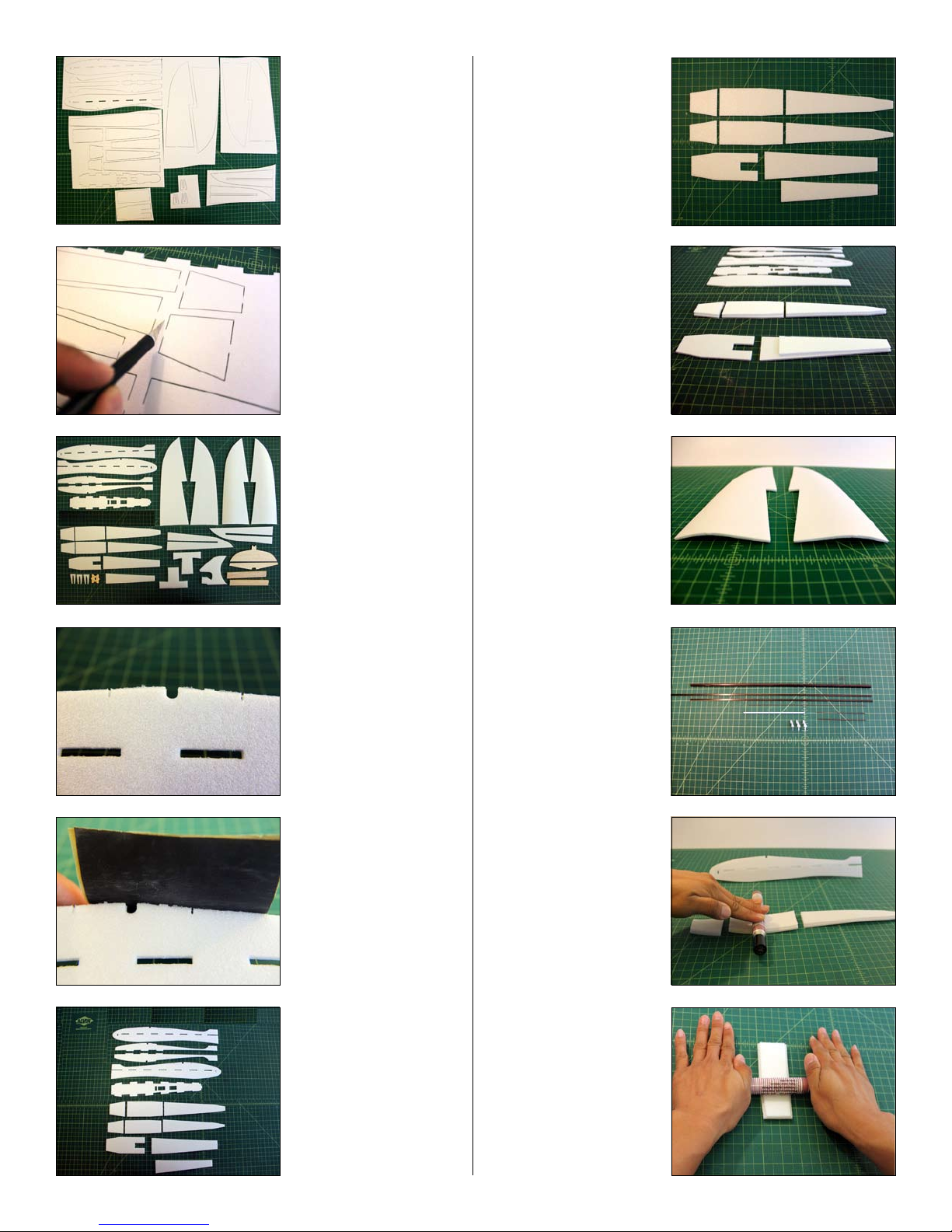
INCLUDED IN THIS KIT:
• All laser cut Depron parts
• Balsa ailerons, balsa horizontal stabilizer, and balsa elevator
• Plywood motor mount
• 3 Pushrods + 1 Pushrod tube
• 3 Micro control horns
• 1 Carbon ber tube and 2 at spars
• 1 Balsa short stick for servo mount
SPECIFICATION:
• Wing Span: 24 inch
• Length: 17.5 inch
• Dry weight: 5.5 oz
• Ready to Fly Weight: 7.7 oz with 2S 7.4v 1050mAh
NEEDED BUILDING TOOLS:
• Foam Safe / Odorless CA glue + Foam Safe Accelerator
(User Friendly Odorless “UFO” highly recommended)
• Blenderm Hinge Tape or Transparent Scotch Tape
• Sandpaper + Sanding Bar
• Hobby Knife
• Ruler (preferably metal)
REQUIRED EQUIPMENT:
• 4 Channel Transmitter + Micro Receiver (AR6100E, AR6110E or similar)
• 2 Micro Servos (5~8 gram)
(HXT500, SG-50 or Hitec HS-55 or similar)
• Small & Light High KV Outrunner
(HXT 24gram 3000kv, Turnigy 2730 3000kv or similar)
• ESC: 30Amp
• APC Prop: (4.75x4.75 on 3S ONLY), or (5x5~6x5 on 2S only)
• Prop Adapter: 3mm (will t both recommended motors)
• Lipo Battery: Nano-Power 1100mAh 11.1v 35C
• Maximum Battery size: 73x34x18 mm
(Size is very crucial here. This size is the largest t for width and thickness possible in
the small fuselage)

The uncut Depron parts
as you will receive
them.
Begin by carefully cut-
ting all the tabs.
All the parts once cut
out.
The edges may be
burred.
Using 400 grit sand pa-
per give all the edges a
light sanding.
The fuselage section
parts shown here.
Look carefully at this
4 rows of parts. These
parts will be doubled
up.
(Notice the direction of
the taper on the center
sections on the rst 2
rows.)
Double up the parts
and glue them together
as shown. Keep them
centered leaving 3mm
on each left and right
side. The 3 sections
of parts is the bottom
fuselage.
The kit will include 2
wing halves that are
pre-curved. These will
be the top skins of the
wing.
The carbon ber parts
and hardware as in-
cluded.
Using a marker as
a rolling pin, roll the
bottom parts to form
a similar shape as the
bottom of the fuselage.
Use 2 hands and roll
it as if you’re rolling
dough, and it will curve
up.

Glue the fuselage
doublers over the side
pieces. Use left over
scraps to ensure the
parts line up properly
by inserting them in the
slots. (Do not glue the
scraps in!)
Make sure that these
parts line up exactly
when gluing the doubler
VERY IMPORTANT!
Make sure you have a
left and right side with
the doublers on the
inside.
Assemble half a fuse-
lage rst along with the
motor mount by gluing
the center section with
all the tabs. Remember
the doublers need to
be facing toward the
inside.
Glue the remaining
fuselage half together
as shown.
(Don’t forget to install
the motor mount in this
step)
Glue the bottom rear
portion of the fuselage.
For now stop here on
the fuselage and lets
start on the elevator
next.
Sand a bevel on the
stabilizer about 20
degrees.
(It is better to sand a
bevel on both sides
than only on the eleva-
tor.)
Sand a bevel on the
elevator about 20 de-
grees.
Sand the leading edge
of the stabilizer round.
(Sanding rounded lead-
ing edges and tapered
trailing edges will
improve performance,
don’t skip these steps)
Here you can see the
difference: Sanded on
the left and not sanded
on the right.
Use blue painters tape
or masking tape and at-
tach the elevator. Then
sand a taper to the
trailing edge. Don’t over
do it since you will be
sanding both top and
bottom.
Now ip over the tail
and leave on the tape
for now. Again sand
a taper to the trailing
edge. Again don’t over
do it.

This is how it should
look like after sanding
both the top and bottom
to a taper towards the
trailing edge.
Use “transparent”
Scotch tape, (NOT the
“invisible” type)
Or you can use 3M
Blenderm tape, com-
monly referred to as
“Hinge Tape”
Tape the top rst. Trim
any overhanging tape.
Then ip up and tape
the bottom. Again trim
any overhang.
After taping the bot-
tom of the hinge it will
remain ipped up. With
a hard tool, like your
blade handle, press
down and atten the
hinge edge to help it
remain neutral.
With a very sharp
blade lightly score the
scotch tape over the
hole meant for the
control horn. Cut away
a section about 1/4 inch
square.
Here is what your
stabilizer with elevator
attached should look
like. (Note the bevel
on both sides... This is
important that you do it
this way for best perfor-
mance.)
Now insert the stabilizer
into the fuselage and
glue ONLY the bottom
part for now. Make sure
the bevels are facing
toward the bottom.
(Photo shows the fuse-
lage upside down.)
Flip the fuselage back
right-side up. The top
portion where it is being
squeezed should NOT
be glued yet.
It should be free to
open as it is shown
here. We will glue it
later.
Flip over the fuselage
belly up again. Lay out
the remaining bottom
cover parts but do
NOT glue them in at
this point. Just position
them.
Flip the fuselage back
over and check the
front. You can see that
the motor mount does
not let the bottom piece
go all the way in.
PRESS down hard to
leave an imprint.

Remove the part and
look carefully as you
will see the imprint of
the motor mount.
Cut out just the one
layer (3mm deep) of
foam where the imprint
was left. Now it will go
in just ne and add
strength to the motor
mount and foam bond-
ing area.
Now ip the part over
again and attach the
remaining battery hatch
to the piece we just
worked on. Tape it as
you did the elevator.
Keep in mind there is
no bevel though.
Just as you did with the
elevator ip over the
part and tape the under
side. You will now have
a one-way moving
hinge.
Trim along the edges,
do not fold over the
tape. This will allow the
foam to glue nicely into
the fuselage with foam
on foam.
Now insert this as-
sembly into the bottom
part of the fuselage and
ONLY glue the front
part on.
Make sure there is
room for the battery
hatch to open and
close. Again, ONLY
glue the front part on.
The remaining parts of
the fuselage as shown
here. Put aside for now,
we will get back to it
later.
The parts required for
the main wing assem-
bly.
Tape down the left
and right bottom (at)
wings and use the 2 “T”
spacing jigs to set the
proper distance. Make
it secure and use more
tape if needed.
Lay down the carbon
ber tube. But do NOT
glue it in yet.
Lay out the center wing
panels as shown and
glue them in. Do NOT
glue the “T” jigs to this
assembly. After gluing
the center wing panels
and the carbon tube
remove the “T” jigs

Glue the longer 20”
carbon at spar to the
back of the center wing
panel. Make sure it is
centered equally on
the left and right of the
wing. Use wax paper to
keep your ngers clean.
Repeat this process for
the other side.
(In case you don’t get
it: It is being glued to
the trailing edge of the
smaller center wing
panel)
It will require some light
bending. It will bend
very easily as long as
your at spar is
standing vertically and
not laying at.
With the Remaining
shorter at spar repeat
the same process but
on the front leading
edge of the center wing
panel. Again using wax
paper to keep your
ngers clean.
Spraying accelerator
while holding the spar
with the wax paper will
make the end parts that
curve easier to as-
semble.
Use small 1/8” strip of
masking tape to line up
the top cover. This will
help you get the wing
on right with one try
by ipping it over after
you apply glue on the
inside.
Apply glue to sections
in Red. Marking yours
the same way only on
the outer most edges
will help you in later
steps with sanding the
leading and trailing
edges. (Don’t forget
to apply glue on the
Carbon tube also)
Carefully ip over the
top and make sure it is
lined up. Hold it down
with pressure until the
glue starts holding.
Spray accelerator over
the edges to assist.
Cut and trim the balsa
wood aileron stock to
t.
Sand the inside edge
lightly if needed to
form a nice clean edge
for the aileron. Use a
Sanding Bar for even
results.
With the wing upside-
down attach the aileron
so that it will lay at
when right-side up as
shown in the next step.
If your aileron is thicker
than your wing then
sand it down to create
a smooth air ow over
the wing. If it ts nicely
then just leave it as it is.
Again use a sanding
bar.

The trailing edge of
the wing tips will need
sanding.
Sand them down to
closely match the
aileron.
The leading edge is
blunt as shown here.
(You can see the line
where the marker on
the edges will now act
as a guide for you when
sanding)
With the guide line
showing you can be
sure to sand a uniform
rounded edge.
Now ip over the
bottom side and also
sand a slight taper on
the bottom outer trailing
edge of the wing. This
will create some slight
washout
You can see the red
marker lines beneath
the Depron to prevent
you from sanding too
much. Stop before it
starts showing through
too much.
Make sure you use a
sanding bar to ensure
your sanding is uni-
form and level where
needed. This helps
greatly with sanding the
tapered trailing edges.
Here you can see an-
other angle of the taper
at the bottom trailing
edge.
(Bottom side is facing
up in this photo)
More photos to show
the sanding.
Here is a shot of the
shape of the airfoil at
this point. Right now it
is “Flat Bottom” later we
will make it “semi-sym-
metrical” for better high
speed performance.
This photo shows the
wash out better.
Before we sand a bevel
to BOTH the wing and
the aileron.

See here how both
sides are bevelled
Tape the aileron and
trim as shown
Trim both sides and
attach to the wing.
Flip up the aileron and
tape the underside.
Now it will stay ipped
up like the elevator did.
Again using your blade
handle or a pen, press
down on the hinge
edge to help it resist
ipping up.
Measure 1/4 inch from
the inside
And measure 1/4 inch
down. Make a dot and
drill and hole for the
control horn.
Here is another easy
way to trim the tape for
the control horn... Insert
the control horn without
glue and trim the tape
around the edges.
Remember use a sharp
knife and lightly cut it
away.
Remove the control
horn and remove the
tape.
Optional.. You can also
sand the bottom part
of the leading edge to
make the wing Semi-
symmetrical.
Sand a slight curve and
make the leading edge
sharper than just a
round edge.

A close up of the lead-
ing edge. Notice that
the front bottom edge is
lifted up from the oor.
This is all there is to
create the Semi-
symmetrical airfoil.
Your wing and fuselage
will not t perfectly and
will seem to be incor-
rectly spaced. It’s not.
Apply glue into the
gaps and seat the wing
COMPLETELY down in
the slots, then spread
the fuselage walls with
elerator.
Trim to t the included
servo mount wood
piece and glue it right
up behind the front
carbon ber at spar.
The servo should now
be a tight perfect t and
will require you to insert
it diagonally and twist it
into position.
Use 1 screw on the
front wood mount and
use hot glue on the rear
mount over the carbon
tube to secure your
aileron servo.
Now test t the rear
top cover and you will
see that the servo area
needs to be trimmed in
order to close properly.
Trim the area around
the servo.
You will also need to
trim the area on the
front top cover piece.
These 2 top pieces
should not be glued on.
Close them with tape
only for access to the
gear if needed
Now that the top covers
are trimmed to t the
servo, you can compete
the aileron set up as
shown by installing the
control horns and push-
rods. Make Z bends on
the pushrod to make
minor adjustments.
Prepare your elevator
push rod with this zig-
zag bend (or Z bends)
to allow for minor
adjustments if needed.
Also make a Z bend at
the tip to install into the
elevator servo arm.
Use the “T” jigs for
scrap parts to support
the pushrod tube.
2 pieces of the foam
was enough height to
create a nice support
for the pushrod tube.
You may need to trim
the height to close the
top cover.

Cut a V groove to nicely
seat the pushrod tube.
Trim the elevator
control horn as shown
and glue it in the eleva-
tor.
Insert the pushrod into
the inner most hole of
the elevator servo arm
and then tape down the
pushrod inserted in the
tube to line up the end
that will install on the
elevator control horn.
While making sure the
elevator is in neutral
position make an mark
with a sharpie marker
on the position of the
hole of the control horn.
Remove the whole
pushrod with tube. To
be able to better grip
and align your Z bender
tool
Align the Z bender tool
on the mark you made.
Watch the angles to
make sure you position
it properly.
Install the Pushrod on
the control horn rst.
Now insert it on the
inner most hole of the
servo arm then screw
in your servo arm to the
servo.
Push down the slop in
the pushrod and tube
into the V groove of the
support piece. Glue it
in.
Trim the stub on the
under side of the
elevator.
Sand the leading edge
and the trailing edge of
the rudder. Be careful
and gentle not to over
do it and break the tips,
Try to create a
symmetrical shape.

Insert the rudder into
the slots both below
and above the elevator.
It should t easily.
On the top portion, only
apply glue to the ends
and pinch as shown.
Don’t forget to also glue
in the rudder in the bot-
tom slot.
Make sure the rudder
is straight!
Apply glue the stabilizer
as shown.
(The reason we waited
for this step to glue it is
to allow proper align-
ment with the rudder.)
Now back to the top
rear cover that we put
aside in the beginning.
Measure 3” inches from
the rear and mark both
sides.
Cut apart along the 3”
inch marks you just
made.
Again using the marker
roller method, curve up
the end only to match
the fuselage.
Insert it and glue it in.
You will notice 3
different pieces as
shown. They are
different in size only at
the part shown with the
arrows.
Choose the size that
best ts your rudder
after your sanding.
Glue it in. I will discuss
your options for trim-
ming and sanding at
the end so don’t worry
about it’s looks right
now.
This remaining part
should not ever be
glued in.
This will simply be
taped on. This way you
have access to your
servo if you need to
adjust or change it.
It should t snug, then
just tape it down.

And remove it if and
when needed by cutting
the tape.
Now insert your aileron
pushrod on your servo
arm and line up your
control horn.
Again make a mark
on the pushrod with a
sharpie to mark where
you will make the Z
bend. (Before doing this
make a zig-zag bend
in the middle for minor
adjustments if needed.)
Again, you can use
a Zig-Zag bend or
a simple Z bend as
shown here to allow
for minor adjustments
since we are not using
ez-connectors.
It is a very tight t so I
recommend you solder
your motor to the ESC
to allow it to fold inside
the tight fuselage. Test
t it now and cut the
wires shorter if neces-
sary. Also, make sure
your motor is spin-
ning the right way!
Install the motor mount
rst to the rewall. Then
install the motor.
You may have to make
a small access hole to
reach the grub screw to
tighten your motor onto
the motor mount.
The motor may be too
close to the nose of the
fuselage.
Trim it to clear the
motor if needed
Position the ESC as
shown.
You may have to
extend the wires to the
battery connector to
reach the hole for the
wires in front of the
elevator servo.
You can continue
to use the T jigs for
scraps. See next step
Glue the scrap foam
down over the ESC
and wires so you have
clearance to put on the
top cover. This part will
be a tight t.
Use a small receiver.
Also make sure the
battery connector is
tucked under into the
hole and is coming out
under the belly and
accessible through the
battery hatch.

A view of the tight
installation shown
The battery connector
showing through the
hole.
You need to ll this
hole and space under
the front bottom. Cut
scrap piece 3/4” Keep
the battery away from
those sharp screws and
prevent the battery from
sliding too far forward.
Cut more scrap pieces
from the “T” jig.
Fill up the front cavity
ONLY 3/4” deep so that
the battery position will
slide partially into the
nose area and not hit
the screws.
Test t your battery and
check for proper CG.
Once proper CG is
determined ll up the
front cavity to allow
your battery to be
placed on the proper
CG every time. Glue
the scraps in place.
As you did with the
rear hatch, simply tape
down the top cover.
You may want to lightly
sand the edges smooth
before attaching it.
Unless you don’t mind
the way it looks.
The tape over the rear
hatch as shown. Again
lightly sand the edges
rounded while holding
it down before taping
the edges if you want
streamlined rounded
edges
For you to better
understand where to
tape I have used the
blue tape for
demonstration purpose
only. You should use
clear tape on yours.
Sand all edges of your
fuselage as streamlined
as you wish it to be. (Be
careful not to damage
the rudder or horizontal
stabilizer when sanding
the rear section.
Congratulations! You are almost done!
As a last step you should cover the entire fuselage
with clear packing tape to add strength and apply a
coating of water based polyurethane over the entire
plane. The WBPU will help keep the airplane clean.
To see how to cover your plane with tape refer to
the last couple pages of the NANOSHARK manual.
IT IS VERY IMPORTANT TO PROPERLY SET UP
YOUR CONTROL SETTINGS AND THROWS.
PLEASE READ ALL THE INFORMATION ON THE
PAGE BELOW.
Warning! This aircraft is for experienced pilots only.
This is not a PARKFLYER. Although it weighs under
2LBS, its speed can exceed 60mph. Therefore, it does
not qualify as a “Parkyer” as per AMA rules and reg-
ulations. It should be own only in elds specically
reserved for RC aircraft which have been approved by
the AMA. It is highly recommended that you join the
AMA if you are not already a member. If built or own
incorrectly, this plane can cause damage property or
injury to people. User assumes all responsibilty and
risk.

Airplane ight Characteristics:
This micro speed plane is Insanely FAST on the 3S setup PLEASE follow the recommended control set ups including
EXPO, otherwise it will be challenging to y as it is a very responsive high performance design that can be easy and fun
to y if set up properly.
The Babyshark is a high performance design that is fast, responsive, and aerobatic. It can retain its high speed energy in
full elevator yank and bank pylon turns and will get your heart pumping and your knees shaking. PERFECT for you speed
freaks! It is also Extremely maneuverable and can tear up the sky like NO OTHER Depron aircraft it’s size and weight
then slow down for sport ying. But what fun is that when you have a little pocket rocket like this in your control. Which
ever way you like to y this plane it is quite small and it can get away from you fast. So don’t blink and hold on for a
performance you never thought possible from a 3mm Depron foam airplane and wow everyone at the aireld,
Guaranteed!
Alternatively, if you want a fast plane but need to work your way up to it like many pilots, then start with the 2S set up
instead of the 3S on the same motor, ESC, and even the same 4.75x4.75 prop! And you will have your self a very
manageable and still fast micro parkyer that is great ying fun at a more manageable pace. But don’t underestimate this
set up either, it can still tear up the sky, but at a less-than-insane way.
PLEASE FOLLOW THE RECOMMENDED CONTROL THROW SET UP. VERY IMPORTANT!!!
R.T.F. Weight: 7.5 oz. ~ 9.0 oz
Center of Gravity: 1 1/4” from the leading edge at the wing root.
Aileron Throw: Up and Down = 3/16” ~ 5/16”
Dual Rates for 60% low, 90% high
Expo is at your preference 20% to 30%
Elevator Throw: Up and Down = 1/8” ~ 3/16”
Dual Rates 50% low, 60% high
Expo is a MUST at 50% to 70%
~Start with low rates until you are comfortable with the plane and gradually move up to the high rates if you feel the
need.~
Here are the recommended set ups:
Wickedly fast super high performance: (24 Amps / 260+ watts!)
Motor: HexTronik 24 gram 3000 KV
ESC: ZTW 30 Amp (Other ESC’s including Turnigy can not handle the high switching rate of this motor on 3S, this ZTW
30Amp ESC can!)
Battery: Nano-Power 1100mAh 11.1v 35C
Prop: APC 4.75x4.75
Light and fast parkyer:
Motor: HexTronik 24 gram 3000 KV
ESC: ZTW 20 Amp (using a 30Amp ESC will enable you to y both set ups simply by changing the battery)
Battery: Rhino 1050 mAh 2S 7.4v 20C or 30C
Prop: APC 4.75x4.75 or (5x5~6x5 on 2S only!)
Table of contents
Other nanoplanes Toy manuals