www.nano-sense.com All Rights Reserved Tel : 33 (0)1 41 41 00 02 page 4
3. Flush mounting
Use the backbox provided or an airtight insulated backbox with a
waterproofing membrane through which the sheath passes. If the backbox
passes through the sealing plane, seal between the backbox and the partition
with a specific VOC free and silicone free sealant.
Make sure that the backbox doesn’t contain Silicone.
The depth of the case must be at least 40mm.
4. Wiring
Be careful, wiring must be sealed. Incoming air, even slight, would seriously jam the temperature,
humidity and air quality measures.
When the switchboard is located in the heated volume: caulk arrivals between cables and ducts at the
switchboard level.
When the switchboard is out of the heated volume, caulk between cables and ducts before entering the
heated volume. A sealing plug must also be placed between duct and cable reaching the probe to
prevent air entry.
When the sealing of the duct is not possible, use a specific sealant without silicone and VOC.
In case of use of electrical backbox, select an airtight case with sealing
membrane from which the duct passes through. If the case crosses through the
sealing plane (plasterboard), seal between the casing and panel with a special
sealant without silicone and VOC.
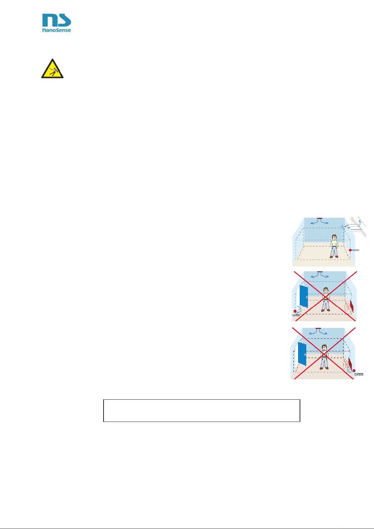
5. Installation
It is recommended to install the probe at the end of the work (after painting and
using silicone-based products)
Connect the 24V power cable to the back of the probe. Just push the stripped
ends (flexible or rigid) into the connector. In case of a multi-strand cable, make
sure to well twist them before inserting them. In case of difficulty, push the
release tab. Respect the polarity (non-destructive).
Make sure to respect the up and down directions indicated on the ventilation grid
otherwise the temperature and humidity measurements will be jammed and the
particles sensor will become dirty.
Screw the probe plate onto the wall box.
Clip the front panel, making sure to position the connector correctly.
If well mounted, the hole for the light sensor shall be on top middle
6. Power on
20 seconds after power-up, the blue status LED and the orange status LED flash together gradually 15
times, at the end of the cycle, the orange LED remains fixed for few seconds, the time to interrogate all
sensors then, only the blue LED "breathes" if the air quality does not require ventilation. If the probe has