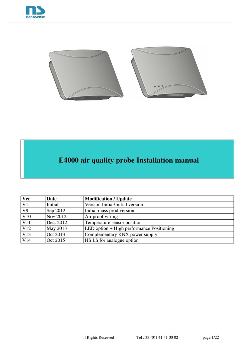
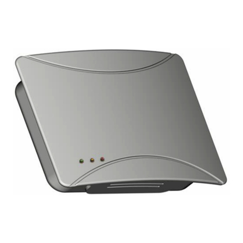
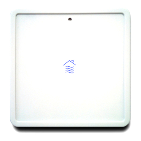
NanoSense EP5000M User manual

Installation Guide Modbus E5000 IAQ probe
page 2/6
Summary
1. Security.............................................................................................................................................................3
2. Positioning........................................................................................................................................................3
3. Flush mounting.................................................................................................................................................5
4. Wiring...............................................................................................................................................................5
5. Installation........................................................................................................................................................5
6. Power on...........................................................................................................................................................6
7. Connections......................................................................................................................................................6
7.1. Power supply....................................................................................................................................................6
8. NFC..................................................................................................................................................................6
9. Disconnection...................................................................................................................................................6

Installation Guide Modbus E5000 IAQ probe
page 3/6
1. Security
WARNING
Danger of death, risk of electric shock and fire!
The installation should only be undertaken by a qualified electrician!
To apply for correct bus and power cables and to activate the device, comply with the state of the art
and standards.
Any intervention or modification to the device will invalidate any warranty claim.
• Do not use this probe in environments with regular exposure to silicon vapors (HMDS) because this
gradually alters the sensitivity of the VOC sensor.
• Do not use the sensors for measuring gas content relating to safety!
• Use the probe only with secured low voltages!
2. Positioning
The position of the probe is crucial vis-à-vis efficiency and energy savings for
ventilation, heating and cooling.
• The probe is designed to ensure air quality; it must be placed in the area of
occupancy of the premise served by outlet vents, on a wall at eyes level
(breathing human level, between 1.5 and 1.8m).
• Avoid drafts (near openings, blowing air, doors, outlet vents) and dead zones
(niche, shelves and curtains).
• Avoid orthogonal walls (corners of room in particular)
• Avoid heat sources and the proximity of occupants (radius of 1 m from
workstation).
• Position the probe vertically on a wall or partition.
This device is not intended for installation in duct or ceilings.
• Avoid direct exposure to sunlight. Consider all seasons sun positions
• The positioning must take into account the desired quality of the ambient light measurement.

Installation Guide Modbus E5000 IAQ probe
page 4/6
Any work not in accordance with this documentation or
changes to the device will invalidate all warranty claims.

Installation Guide Modbus E5000 IAQ probe
page 5/6
3. Flush mounting
Use the multi material backbox provided or an airtight insulated backbox with a
waterproofing membrane through which the sheath passes. If the backbox passes
through the sealing plane, seal between the backbox and the partition with a
specific VOC free and silicone free sealant. If ordering the backbox separately:
Make sure that the backbox doesn’t contain Silicone.
The internal depth of the case must be at least 50mm.
The internal diameter (about 64mm) shall have a 40x40mm space free up to
the bottom)
The space between screws shall be 60mm
The height of the screws heads shall be 2mm max)
4. Wiring
Be careful, wiring must be sealed. Incoming air, even slight, would seriously jam the
temperature, humidity and air quality measures.
When the switchboard is located in the heated volume: caulk arrivals between cables
and ducts at the switchboard level.
When the switchboard is out of the heated volume, caulk between cables and ducts
before entering the heated volume. A sealing plug must also be placed between
duct and cable reaching the EP5000 probe to prevent air entry.
When the sealing of the duct is not possible, use a specific sealant without silicone
and VOC.
In case of use of electrical backbox, select an airtight case with sealing membrane
from which the duct passes through. If the case crosses through the sealing plane
(plasterboard), seal between the casing and panel with a special sealant without
silicone and VOC.
Connectors are specified for rigid cable 18 to 24 AWG (1 to 0.5mm dia.) or
twisted 20 to 22 AWG (0.8 to 0.65mm dia.)
The connectors accept two 0.8mm cables on the same terminal in order to chain
several sensors. Beware of line losses, a 0.8mm cable has a resistance of 21Ω
per Km.
5. Installation
It is recommended to install the probe at the end of the work (after painting and using
silicone-based products).
Connect the ModBus and the 24V DC Power Supply pair cables on the terminal
block on the back of the product. Pay attention to marking: Modbus A & B and
power supply polarity.
Just push the stripped ends (flexible or rigid) into the connector. In case of a multi-
strand cable, make sure to well twist them before inserting them. In case of
difficulty, push the release tab. Respect the polarity (non-destructive).
Make sure to respect the Up marking otherwise the temperature and humidity
measurement will be jammed.
Screw the plate on the backbox.
Plug the front panel onto the plate. Pay attention to the position of the connector in
the back of the front plate.
If well mounted, the transparent window of the light sensor shall be on top middle.
Ø 67/68

Installation Guide Modbus E5000 IAQ probe
page 6/6
6. Power on
Few seconds after power-up, all LEDs will be activated individually for a visual test. At the end of the
cycle, failure message made of blink between orange and red LED may appear during few seconds, the
time to interrogate all sensors then, the blue LED shall "breathes" if the air quality is good enough. The
start-up cycle includes built in tests and visual checks of LEDs
The cycle lasts about one minute in total.
LEDs indicate faults as follows:
LED code on the front panel
Identification #
Defective FRU
No LED active
NA
Power supply failure suspected or
probe power supply board
Red LED on for 5 seconds
Followed by a yellow flash
1
Front panel board.
Followed by 2 yellow flashes
2
Single band CO2 sensor module.
Followed by 3 yellow flashes
3
Dual band CO2 sensor module
Followed by 4 yellow flashes
4
VOC sensor module
Followed by 5 yellow flashes
5
Motherboard
Followed by 6 yellow flashes
6
Interconnection board
Followed by 7 yellow flashes
7
Particle sensor board
Followed by 8 yellow flashes
8
Power supply board
Red LED blinking
9
Multiple failures
Alternation Red Blue
10
Perishable sensor reaching the end
of life.
All LEDs blinking
11
No communication between front
panel and probe. (after 30 seconds)
7. Connections
7.1. Power supply
The power supply must be continuous (DC) and between 12 and 32V (24V nominal).
8. NFC
Used for commissioning (See commissioning and App manuals)
9. Disconnection
This manual suits for next models
1
Table of contents
Other NanoSense Measuring Instrument manuals


