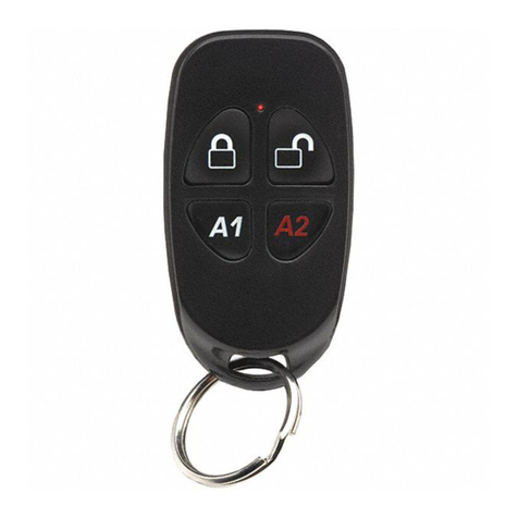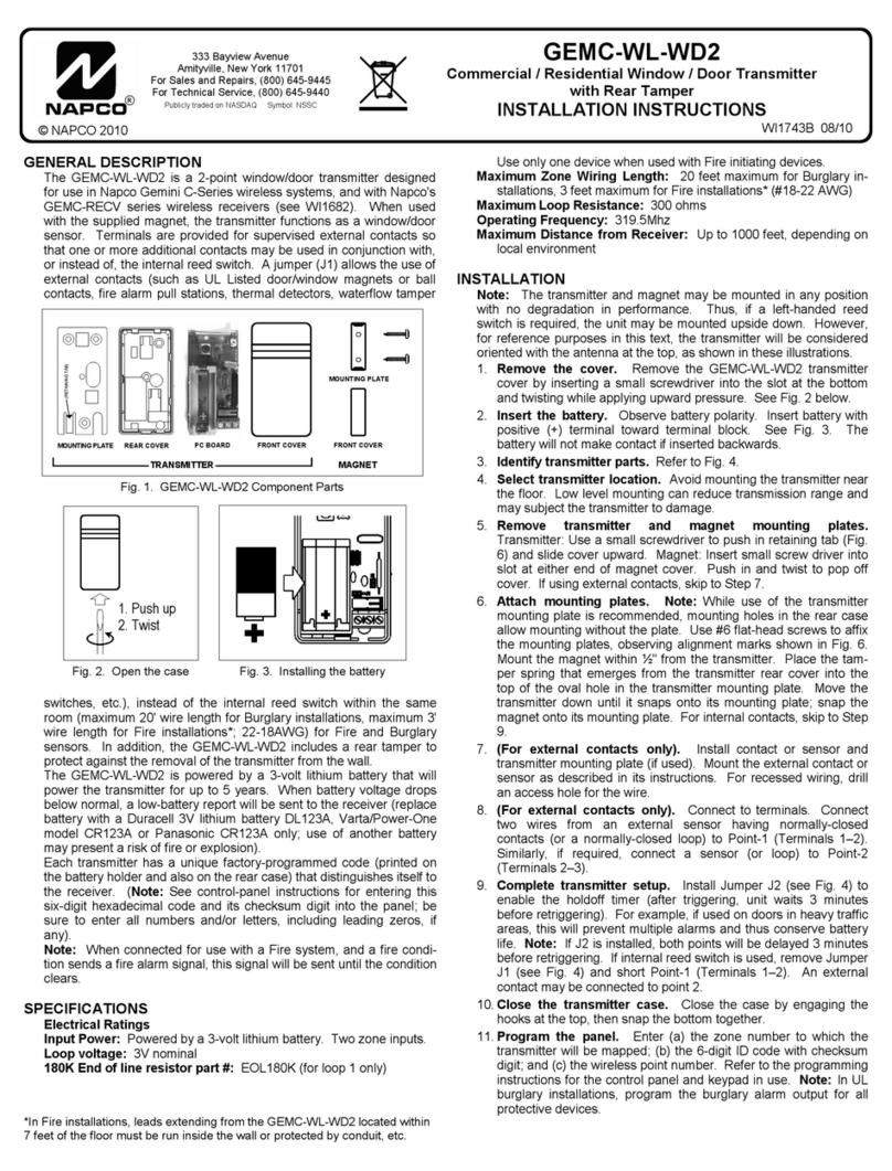
(1) If the GEM-KEYF is used to arm and/or disarm the
system, the control panel must be programmed to
provide a single chirp on arming and a double chirp
on disarming. A listed alarm bell or horn is to be
used.
(2) Program the burglary output for all protection de-
vices.
BATTERY REPLACEMENT
Replace with two Energizer 386 1.5V batteries.
1. Remove the screw that secures the case and lift off the
top cover.
2. Remove the rubber Button Assembly.
3. With the Key Ring Hole facing upwards carefully lift the
top circuit board to allow removal of batteries from bot-
tom circuit board.
4. Remove the bottom
plastic tab to replace
the bottom battery and
slide the battery out to
the bottom. Insert the
plastic tab back into
the circuit board.
5. Replace the top bat-
tery by sliding it out to
the right.
6. Reassemble the case
and slip the neckchain
through the eyelet.
NAPCO SECURITY SYSTEMS, INC. (NAPCO) warrants its products to
be free from manufacturing defects in materials and workmanship for thirty-six
months following the date of manufacture. NAPCO will, within said period, at its
option, repair or replace any product failing to operate correctly without charge
to the original purchaser or user.
This warranty shall not apply to any equipment, or any part thereof, which
has been repaired by others, improperly installed, improperly used, abused,
altered, damaged, subjected to acts of God, or on which any serial numbers
have been altered, defaced or removed. Seller will not be responsible for any
dismantling or reinstallation charges.
THERE ARE NO WARRANTIES, EXPRESS OR IMPLIED, WHICH
EXTEND BEYOND THE DESCRIPTION ON THE FACE HEREOF. THERE
IS NO EXPRESS OR IMPLIED WARRANTY OF MERCHANT ABILITY OR A
WARRANTY OF FITNESS FOR A PARTICULAR PURPOSE. ADDITION-
ALLY, THIS WARRANTY IS IN LIEU OF ALL OTHER OBLIGATIONS OR
LIABILITIES ON THE PART OF NAPCO.
Any action for breach of warranty, including but not limited to any implied
warranty of merchant ability, must be brought within the six months following
the end of the warranty period.
IN NO CASE SHALL NAPCO BE LIABLE TO ANYONE FOR ANY
CONSEQUENTIAL OR INCIDENTAL DAMAGES FOR BREACH OF THIS
OR ANY OTHER WARRANTY, EXPRESS OR IMPLIED, EVEN IF THE
LOSS OR DAMAGE IS CAUSED BY THE SELLER'S OWN NEGLIGENCE
OR FAULT.
In case of defect, contact the security professional who installed and
maintains your security system. In order to exercise the warranty, the product
must be returned by the security professional, shipping costs prepaid and in-
sured to NAPCO. After repair or replacement, NAPCO assumes the cost of
returning products under warranty. NAPCO shall have no obligation under this
warranty, or otherwise, if the product has been repaired by others, improperly
installed, improperly used, abused, altered, damaged, subjected to accident,
nuisance, flood, fire or acts of God, or on which any serial numbers have been
altered, defaced or removed. NAPCO will not be responsible for any disman-
tling, reassembly or reinstallation charges.
This warranty contains the entire warranty. It is the sole warranty and any
prior agreements or representations, whether oral or written, are either merged
herein or are expressly canceled. NAPCO neither assumes, nor authorizes
any other person purporting to act on its behalf to modify, to change, or to as-
sume for it, any other warranty or liability concerning its products. In no event
shall NAPCO be liable for an amount in excess of NAPCO's original selling
price of the product, for any loss or damage, whether direct, indirect, incidental,
consequential, or otherwise arising out of any failure of the product. Seller's
warranty, as herein above set forth, shall not be enlarged, diminished or af-
fected by and no obligation or liability shall arise or grow out of Seller's render-
ing of technical advice or service in connection with Buyer's order of the goods
furnished thereunder.
NAPCO RECOMMENDS THAT THE ENTIRE SYSTEM BE COM-
PLETELY TESTED WEEKLY.
Warning: Despite frequent testing, and due to, but not limited to, any or all
of the following; criminal tampering, electrical or communications disruption, it
is possible for the system to fail to perform as expected. NAPCO does not
represent that the product/system may not be compromised or circumvented;
or that the product or system will prevent any personal injury or property loss
by burglary, robbery, fire or otherwise; nor that the product or system will in all
cases provide adequate warning or protection. A properly installed and main-
tained alarm may only reduce risk of burglary, robbery, fire or otherwise but it is
not insurance or a guarantee that these events will not occur. CONSE-
QUENTLY, SELLER SHALL HAVE NO LIABILITY FOR ANY PERSONAL
INJURY, PROPERTY DAMAGE, OR OTHER LOSS BASED ON A CLAIM
THE PRODUCT FAILED TO GIVE WARNING. Therefore, the installer should
in turn advise the consumer to take any and all precautions for his or her safety
including, but not limited to, fleeing the premises and calling police or fire de-
partment, in order to mitigate the possibilities of harm and/or damage.
NAPCO is not an insurer of either the property or safety of the user's
family or employees, and limits its liability for any loss or damage including
incidental or consequential damages to NAPCO's original selling price of the
product regardless of the cause of such loss or damage.
Some states do not allow limitations on how long an implied warranty
lasts or do not allow the exclusion or limitation of incidental or consequential
damages, or differentiate in their treatment of limitations of liability for ordinary
or gross negligence, so the above limitations or exclusions may not apply to
you. This Warranty gives you specific legal rights and you may also have other
rights which vary from state to state.
NAPCO SECURITY LIMITED WARRANTY
Napco Security Systems, Inc. 333 Bayview Avenue, Amityville, New York 11701 For Sales and Repairs, (800) 645-9445 For Technical Service, (800) 645-9440
Publicly traded on NASDAQ Symbol: NSSC
Top View of Bottom Circuit Board
for Battery Replacement
CAUTION: Changes or modifications not expressly approved by manufacturer could void
the user’s authority to operate the equipment.
RADIO AND TELEVISION INTERFERENCE
This equipment has been tested and found to comply with the limits pursuant to Part 15 of
the FCC rules. These limits are designed to provide reasonable protection against harmful
interference in a residential installation. This equipment generates, uses and can radiate
radio frequency energy and, if not installed and used in accordance with the instructions,
may cause harmful interference to radio communications. However, there is no guaran-
tee that interference will not occur in a particular installation. If this equipment does cause
harmful interference to radio or television reception, which can be determined by turning
the equipment off and on, the user is encouraged to try to correct the interference by one
or more of the following measures:
--Reorient or relocate the receiving antenna.
--Increase the separation between the equipment and the receiver.
--Connect the equipment into an outlet on a circuit different from that to which the
receiver is connected.
Consult the dealer or an experienced radio/TV technician for help.
You may also find helpful the following booklet, prepared by the FCC: "How to Identify
and Resolve Radio-TV Interference Problems." This booklet is available from the U.S.
Government Printing Office, Washington D.C. 20402.
Changes and Modifications not expressly approved by the manufacturer or registrant of
this equipment can void your authority to operate this equipment under Federal Commu-
nications Commissions rules.
PART 15 MANUAL STATEMENT


