AWT420 UNIVERSAL 4-WIRE, DUAL-INPUT TRANSMITTER | COM/AWT420/ETHERNET-EN REV. C 7
5 Configuration
Ethernet menus
Ethernet menus are accessed via the Communication level. Refer to Operating Instruction OI/AWT420-EN for menu navigation.
Menu Comment Default
Web Server Submenu that allows the configuration of the built-in web server.
DHCP
•
•
Enabled
IP Address Enter the IP Address to be assigned to the transmitter.
The IP Address is used by the IP Protocol to distinguish among different devices.
Subnet Mask
Class default
Default Gateway
Note: this setting is required only if the device and the PC running the web browser/FTP client are on
different IP subnetworks.
DNS IP Address
the name resolution of IP Addresses.
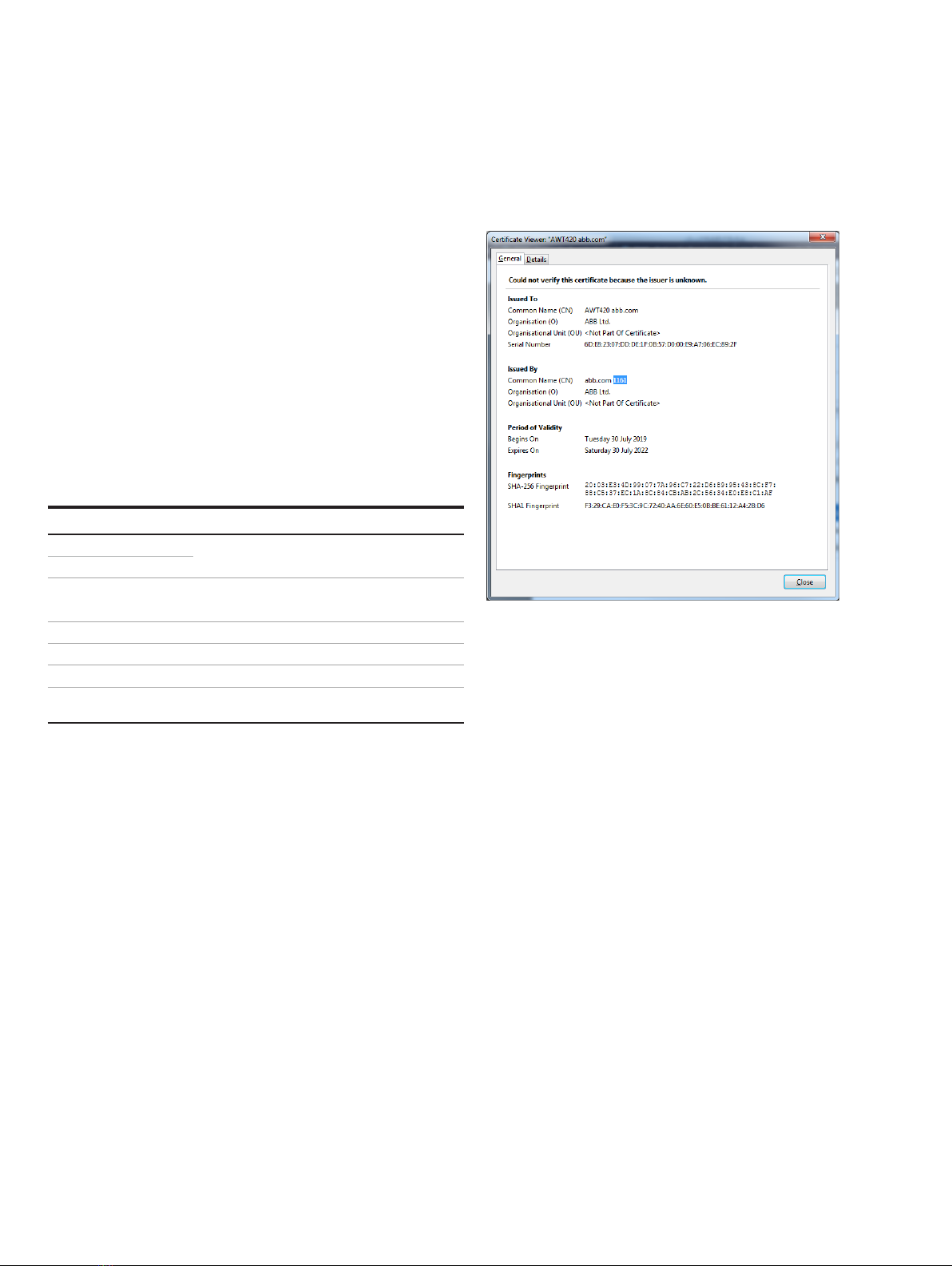
Secure Connection Enable or disable the SSL/TLS (Secure Socket Layer/Transport Layer Security) layer to establish secure
connections over a public network with a web browser. When enabled, remote connections are
established after an authentication phase via a security certificate (explained later).
When Secure Connection is Enabled, it is necessary to configure the Port Number option accordingly.
When Secure Connection is Enabled the web protocol used is HTTPS, otherwise HTTP.
Enabled
Disable Webserver Select Enabled to allow remote connections to the device with a web browser Enabled
Port Number Configures the Port Number from which the transmitter listens for connections requests. This
configuration must be changed according to the configuration of the Secure Connection parameter.
Valid values are:
• HTTPS
• HTTP
FTP Submenu to configure the FTP functionality.
Port Number Configures the Port Number from which the transmitter listens for connections requests.
Disable FTP Select Enabled to allow remote connections to the device with either an FTP client or a web browser
(Read Only access, in the latter case)
Enabled
Secure Connection Enable or disable the SSL/TLS (Secure Socket Layer/Transport Layer Security) layer to establish secure
connections over a public network with a web browser. When enabled, remote connections are
established after an authentication phase via a security certificate (see Certificate management and
storage, ).
Security Certificate .
First Provisioning Performs the first provisioning of the device. To be used when the device is expected to be Inter-net
facing.
This option performs the following operations:
•
•
• Creation of the first self-signed digital certificate to be used during the secure connection
establishment
After this operation is completed, the device is ready to be connected to the Internet. The digital
N/A
Certificate Renew Performs the renewal of the device’s digital certificate. To be used after expiration of the current one.
See for more details.
N/A
Device Identifier
First Provisioning, for details.
(not provisioned)
User Name Allows the configuration of the web server and FTP server user. advanced
Password Allows the configuration of the associated password to access both the web server and the FTP server.
The user/plant administrator is advised to change the default password upon device commissioning to
restrict access to authorized personnel only.
advanced
MAC Address Shows the MAC Address of the Ethernet device. This value is read-only. N/A