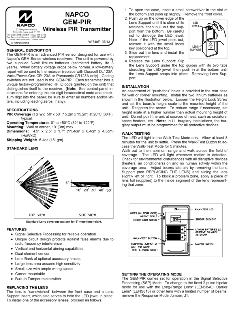
NAPCO GEM-PIR User manual

NAPCO
GEM-PIR
Wireless PIR Transmitter
GENERAL DESCRIPTION
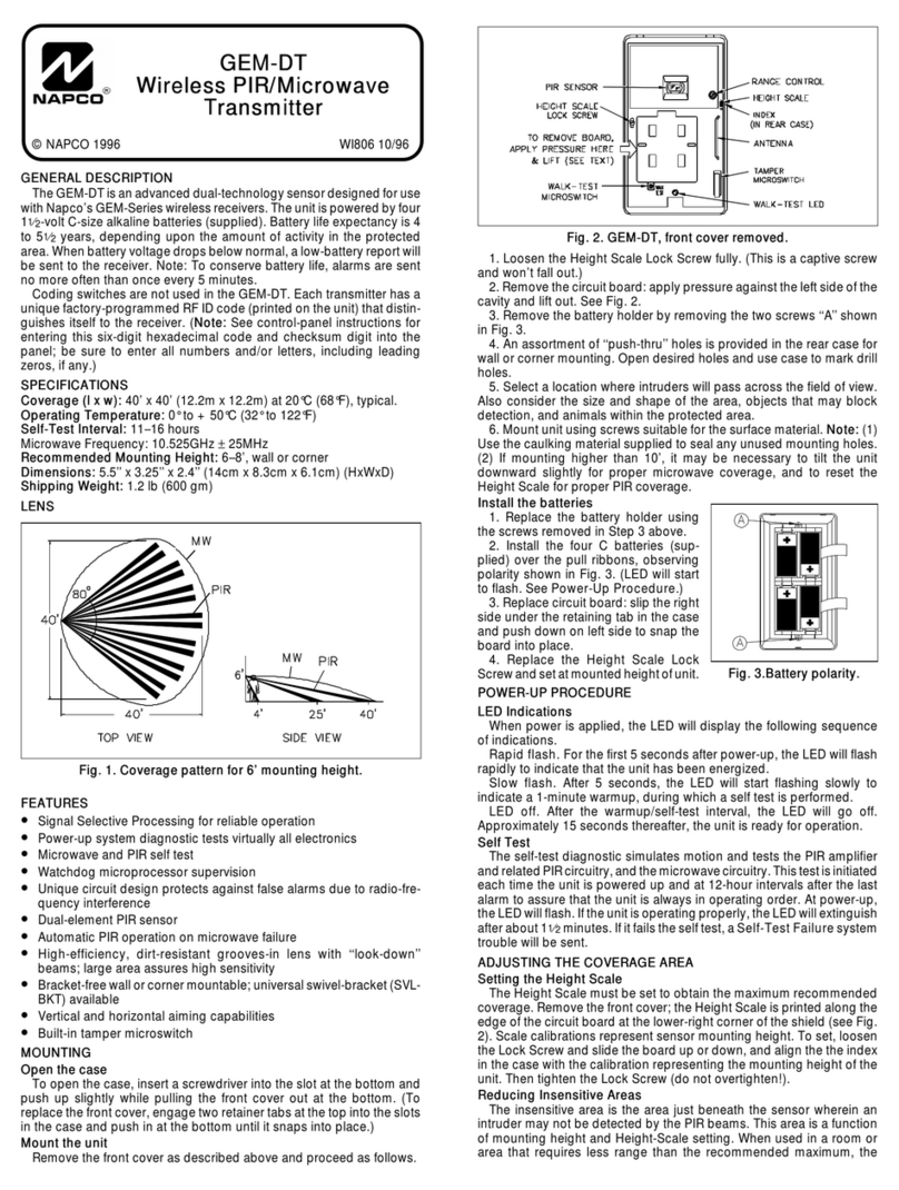
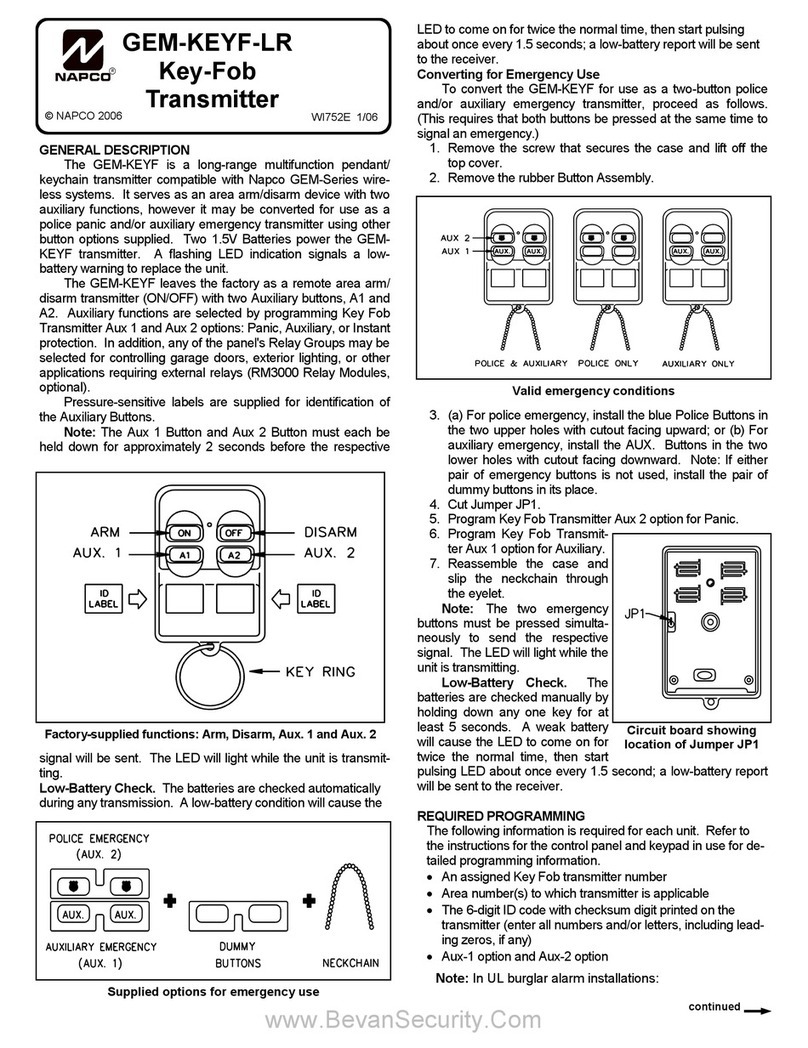
The GEM-PIR is an advanced PIR sensor designed for use with
Napco's GEM-Series wireless receivers. The unit is powered by
two supplied 3-volt lithium batteries (estimated battery life 3
years). When battery voltage drops below normal, a low-battery
report will be sent to the receiver (replace with Duracell DL123A,
Varta/Power-One CR123A or Panasonic CR123A only). Coding
switches are not used in the GEM-PIR. Each transmitter has a
unique factory-programmed RF ID code (printed on the unit) that
distinguishes itself to the receiver. (Note: See control-panel in-
structions for entering this six digit hexadecimal code and check-
sum digit into the panel; be sure to enter all numbers and/or let-
ters, including leading zeros, if any).
SPECIFICATIONS
PIR Coverage (l x w): 50' x 50' (15.2m x 15.2m) at 20°C (68°F),
typical.
Operating Temperature: 0° to +50°C (32° to 122°F)
Mounting: Wall or corner, 10' (3m) max.
Dimensions: 4.5'' x 2.5'' x 1.7'' (11.4cm x 6.4cm x 4.3cm)
(HxWxD)
Shipping Weight: 6.4oz (181gm)
STANDARD LENS
FEATURES
•Signal Selective Processing for reliable operation
•Unique circuit design protects against false alarms due to
radio-frequency interference
•Vertical and horizontal aiming capabilities
•Dual-element sensor
•Lens Bank of optional accessory lenses
•Large lens area assures high sensitivity
•Small size with ample wiring space
•Corner mountable
•Built-in Tamper microswitch
REPLACING THE LENS
The lens is ''sandwiched'' between the front case and a Lens
Support insert, which also serves to hold the LED jewel in place.
To install one of the accessory lenses, proceed as follows.
WI749F 07/13
1. To open the case, insert a small screwdriver in the slot at
the bottom and push up slightly. Remove the front cover.
2. Push up on the lower edge of the
Lens Support until it is clear of its
retainers, then pull out the sup-
port from the bottom. Be careful
not to dislodge the LED jewel.
Note: If the LED jewel pops out,
reinsert it with the small index
key positioned at the top.
3. Slide out the lens and install the
replacement.
4. Replace the Lens Support: Slip
the Lens Support under the top guides with its two tabs
straddling the LED jewel, then push in at the bottom until
the Lens Support snaps into place. Removing Lens Sup-
port.
INSTALLATION
An assortment of ''push-thru'' holes is provided in the rear case
for wall or corner mounting. Install the two lithium batteries as
shown in the illustration below. Loosen the Height Lock Screw
and set the board's height scale to the mounted height of the
unit. Retighten the screw. To reduce range if necessary, set
height scale at a higher number than actual mounting height of
unit. Do not point the unit at sources of heat, such as radiators,
space heaters, etc. Note: In UL burglary installations, the bur-
glary output must be programmed for all protective devices.
WALK TESTING
The LED will light in the Walk-Test Mode only. Allow at least 3
minutes for the unit to settle. Press the Walk-Test Button to ac-
cess the Walk-Test Mode for 5 minutes.
Walk out to the maximum range and walk across the field of
coverage. The LED will light whenever motion is detected.
Check for environmental disturbances with all disruptive devices
(heaters, air conditioners) on and no human activity within the
coverage area. Adjust beams laterally by removing the Lens
Support (see REPLACING THE LENS) and sliding the lens
slightly left or right. To block a problem zone, apply a piece of
lens foil (supplied) to the inside segment of the lens represent-
ing that zone.
SETTING THE OPERATING MODE
The GEM-PIR comes set for operation in the Signal Selective
Processing (SSP) Mode. To change to the fixed 2-pulse bipolar
mode for use with the Long-Range Lens* (LENS840), Barrier
Lens* (LENS818) or other lens with a limited number of beams,
remove the Response-Mode Jumper, J1.
333 Bayview Avenue
Amityville, New York 11701
For Sales and Repairs, (800) 645-9445
For Technical Service, (800) 645-9440
Publicly traded on NASDAQ Symbol: NSSC
© NAPCO 2013
Standard Lens coverage pattern for 6' mounting height.
PUSH
UP
LENS
SUPPORT
LED
JEWEL

NAPCO SECURITY SYSTEMS, INC. (NAPCO)
warrants its products to be free from manufacturing
defects in materials and workmanship for thirty-six
months following the date of manufacture. NAPCO will,
within said period, at its option, repair or replace any
product failing to operate correctly without charge to
the original purchaser or user.
This warranty shall not apply to any equipment, or any
part thereof, which has been repaired by others,
improperly installed, improperly used, abused, altered,
damaged, subjected to acts of God, or on which any
serial numbers have been altered, defaced or removed.
Seller will not be responsible for any dismantling or
reinstallation charges.
THERE ARE NO WARRANTIES, EXPRESS OR
IMPLIED, WHICH EXTEND BEYOND THE
DESCRIPTION ON THE FACE HEREOF. THERE IS
NO EXPRESS OR IMPLIED WARRANTY OF
MERCHANTABILITY OR A WARRANTY OF FITNESS
FOR A PARTICULAR PURPOSE. ADDITIONALLY,
THIS WARRANTY IS IN LIEU OF ALL OTHER
OBLIGATIONS OR LIABILITIES ON THE PART OF
NAPCO.
Any action for breach of warranty, including but not
limited to any implied warranty of merchantability, must
be brought within the six months following the end of
the warranty period. IN NO CASE SHALL NAPCO BE
LIABLE TO ANYONE FOR ANY CONSEQUENTIAL
OR INCIDENTAL DAMAGES FOR BREACH OF THIS
OR ANY OTHER WARRANTY, EXPRESS OR
IMPLIED, EVEN IF THE LOSS OR DAMAGE IS
CAUSED BY THE SELLER'S OWN NEGLIGENCE OR
FAULT.
In case of defect, contact the security professional who
installed and maintains your security system. In order
to exercise the warranty, the product must be returned
by the security professional, shipping costs prepaid and
insured to NAPCO. After repair or replacement,
NAPCO assumes the cost of returning products under
warranty. NAPCO shall have no obligation under this
warranty, or otherwise, if the product has been repaired
by others, improperly installed, improperly used,
abused, altered, damaged, subjected to accident,
nuisance, flood, fire or acts of God, or on which any
serial numbers have been altered, defaced or removed.
NAPCO will not be responsible for any dismantling,
reassembly or reinstallation charges.
This warranty contains the entire warranty. It is the sole
warranty and any prior agreements or representations,
whether oral or written, are either merged herein or are
expressly cancelled. NAPCO neither assumes, nor
authorizes any other person purporting to act on its
behalf to modify, to change, or to assume for it, any
other warranty or liability concerning its products.
In no event shall NAPCO be liable for an amount in
excess of NAPCO's original selling price of the product,
for any loss or damage, whether direct, indirect,
incidental, consequential, or otherwise arising out of
any failure of the product. Seller's warranty, as
hereinabove set forth, shall not be enlarged, diminished
or affected by and no obligation or liability shall arise or
grow out of Seller's rendering of technical advice or
service in connection with Buyer's order of the goods
furnished hereunder.
NAPCO RECOMMENDS THAT THE ENTIRE
SYSTEM BE COMPLETELY TESTED WEEKLY.
Warning: Despite frequent testing, and due to, but not
limited to, any or all of the following; criminal tampering,
electrical or communications disruption, it is possible
for the system to fail to perform as expected. NAPCO
does not represent that the product/system may not be
compromised or circumvented; or that the product or
system will prevent any personal injury or property loss
by burglary, robbery, fire or otherwise; nor that the
product or system will in all cases provide adequate
warning or protection. A properly installed and
maintained alarm may only reduce risk of burglary,
robbery, fire or otherwise but it is not insurance or a
guarantee that these events will not occur.
CONSEQUENTLY, SELLER SHALL HAVE NO
LIABILITY FOR ANY PERSONAL INJURY,
PROPERTY DAMAGE, OR OTHER LOSS BASED ON
A CLAIM THE PRODUCT FAILED TO GIVE
WARNING. Therefore, the installer should in turn
advise the consumer to take any and all precautions for
his or her safety including, but not limited to, fleeing the
premises and calling police or fire department, in order
to mitigate the possibilities of harm and/or damage.
NAPCO is not an insurer of either the property or safety
of the user's family or employees, and limits its liability
for any loss or damage including incidental or
consequential damages to NAPCO's original selling
price of the product regardless of the cause of such
loss or damage.
Some states do not allow limitations on how long an
implied warranty lasts or do not allow the exclusion or
limitation of incidental or consequential damages, or
differentiate in their treatment of limitations of liability
for ordinary or gross negligence, so the above
limitations or exclusions may not apply to you. This
Warranty gives you specific legal rights and you may
also have other rights which vary from state to state.
NAPCO LIMITED WARRANTY
Other manuals for GEM-PIR
2
Table of contents
Other NAPCO Transmitter manuals