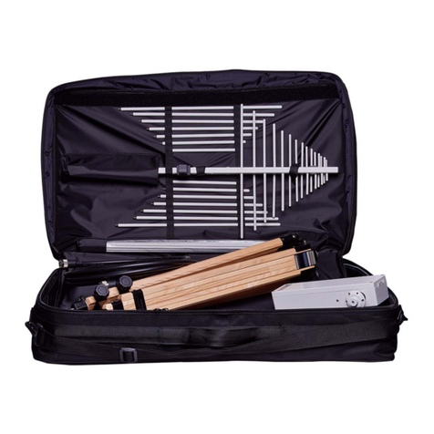
NARDA PMM RA-01 User manual

NARDA
Safety
Test
Solutions
S.r.l. Socio Unico
Sales & Support:
Via Leonardo da Vinci, 21/23
20090 Segrate (MI) - ITALY
Tel.: +39 02 2699871
Fax: +39 02 26998700
Manufacturing Plant:
Via Benessea, 29/B
17035 Cisano sul Neva (SV)
Tel.: +39 0182 58641
Fax: +39 0182 586400
http://www.narda-sts.it
SERIAL NUMBER OF THE INSTRUMENT
You can find the Serial Number in a side of the box.
Serial Number is in the form: 0000X00000.
The first four digits and the letter are the Serial Number prefix, the last five digits are
the Serial Number suffix. The prefix is the same for identical instruments, it changes
only when a configuration change is made to the instrument.
The suffix is different for each instrument.
Document RA01EN-71011 – Copyright © NARDA 2017
User’s Manual
PMM RA-01
PMM RA-01-HV
ACTIVE ROD ANTENNA

II Note and symbols
NOTE:
® Names and Logo are registered trademarks of Narda Safety Test Solutions GmbH and L3 Communications
Holdings, Inc. – Trade names are trademarks of the owners.
If the instrument is used in any other way than as described in this User’s Manual, it
may become unsafe.
Before using this product, the related documentation must be read with great care and fully understood to familiarize
with all the safety prescriptions.
To ensure the correct use and the maximum safety level, the User shall know all the instructions and
recommendations contained in this document.
This product is a Safety Class I instrument according to IEC classification and has
been designed to meet the requirements of EN61010-1 (Safety Requirements for
Electrical Equipment for Measurement, Control and Laboratory Use).
In accordance with the IEC classification, the power supply of this product meets requirements Safety Class III and
Installation Category II (having double insulation and able to carry out mono-phase power supply operations).
It complies with the requirements of Pollution Class II (usually only non-conductive pollution). However,
occasionally it may become temporarily conductive due to condense on it.
The information contained in this document is subject to change without notice.
KEY TO THE ELECTRIC AND SAFETY SYMBOLS:
You now own a high-quality instrument that will give you many years of reliable service.
Nevertheless, even this product will eventually become obsolete. When that time
comes, please remember that electronic equipment must be disposed of in accordance
with local regulations. This product conforms to the WEEE Directive of the European
Union (2002/96/EC) and belongs to Category 9 (Monitoring and Control Instruments).
You can return the instrument to us free of charge for proper environment friendly
disposal. You can obtain further information from your local NARDA Sales Partner or
by visiting our website at www.narda-sts.it .
Warning, danger of electric shock
Earth
Read carefully the Operating Manual and its
instructions, pay attention to the safety symbols.
Unit Earth Connection
Earth Protection
Equipotential
KEY TO THE SYMBOLS USED IN THIS DOCUMENT:
The DANGER sign draws attention to a serious risk to a person’s safety,
which, if not avoided, will result in death or serious injury. All the
precautions must be fully understood and applied before proceeding.
The WARNING sign indicates a hazardous situation, which, if not avoided,
could result in death or serious injury. All the precautions must be fully
understood and applied before proceeding.
The CAUTION sign indicates a hazardous situation, which, if not avoided,
could result in minor or moderate injury.
The NOTICE sign draws attention to a potential risk of damage to the
apparatus or loss of data.
The NOTE sign draws attention to important information.

Contents III
Contents
Safety recommendations and instructions.………......
RA-01 EC Declaration of Conformity ...........................
RA-01-MIL EC Declaration of Conformity ....................
RA-01-HV EC Declaration of Conformity .....................
Page
V
VI
VII
VIII
1 General Information
1.1 Documentation………………………………….………
1.2 Introduction to the PMM RA-01………………..…......
1.3 Calibration of the PMM RA-01...................................
1.4 Instrument Items…...................................….............
1.5 Optional accessories……....................…....…...........
1.6 Main specifications……………………………………..
1.7 Main Features…………………………………………..
1.8 PMM RA-01 parts……….……………………………...
Page
1-1
1-2
1-2
1-2
1-2
1-3
1-3
1-4
2 Mounting Instructions Page
2.1 Introduction………………………………………………. 2-1
2.2 Initial inspection…………………………………………. 2-1
2.3 Environment……………………………………………… 2-1
2.4 Return for service……………………………………….. 2-1
2.5 Equipment cleaning…………………………………….. 2-1
2.6 PMM RA-01 mounting instructions……..…………….. 2-2
3 Using PMM RA-01 Page
3.1 How it works……………………………………………… 3-1
3.2 Power Switch……………………………………………. 3-1
3.3 Battery Charging………………………………………… 3-1
3.4 ESD Risks………………………………………………... 3-1
3.5 Principles of operation………………………………….. 3-1
3.6 Antenna Factor………………………………………….. 3-2
3.7 Procedure of calibration………………………………… 3-2
4 Accessories Page
4.1 Introduction ….…………………………..……...……… 4-1
4.2 Preliminary inspection …………………..….…………. 4-1
4.3 Work environment ……....………………..…………… 4-1
4.4 Return for repair …….………………..………………... 4-1
4.5 Cleaning ……………………………..………………….. 4-1
4.6 PMM TR-01A Set (optional)…………………………… 4-2
4.6.1 TR-01A Set ……….…………..……………………… 4-2
4.6.2 RA-01 installation on TR-01A Wooden tripod...…… 4-4

IV Contents
Figures
Figure
1-1
1-2
1-3
4-1
4-2
4-3
4-4
4-5
PMM RA-01 Active Rod Antenna……………………........
PMM RA-01 parts.…….…………………………………….
PMM RA-01 front view ……………………...……………..
PMM TR01 Wooden Tripod………………………………..
Adjustable joint ……………………………………………..
Column strengthener……………………………………….
Soft carrying case…………………………………………..
RA-01 parts and assembly………………………………...
Page
1-1
1-4
1-4
4-2
4-2
4-3
4-3
4-4
Tables
Table
1-1
1-2
4-1
4-2
4-3
Technical Specification………………….…………………..
Main features…………………………………………..……..
PMM TR-01 Wooden tripod with extension………………
Column strengthener Specifications………………………
Soft carrying case…………………………………………..
Page
1-3
1-3
4-2
4-3
4-3

Safety consideration V
SAFETY RECOMMENDATIONS AND INSTRUCTIONS
This product has been designed, produced and tested in Italy, and it left the factory in conditions fully
complying with the current safety standards. To maintain it in safe conditions and ensure correct use,
these general instructions must be fully understood and applied before the product is used.
•When the device must be connected permanently, first provide effective grounding;
•If the device must be connected to other equipment or accessories, make sure they are all safely
grounded;
•In case of devices permanently connected to the power supply, and lacking any fuses or other
devices of mains protection, the power line must be equipped with adequate protection
commensurate to the consumption of all the devices connected to it;
•In case of connection of the device to the power mains, make sure before connection that the
voltage selected on the voltage switch and the fuses are adequate for the voltage of the actual
mains;
•Devices in Safety Class I, equipped with connection to the power mains by means of cord and plug,
can only be plugged into a socket equipped with a ground wire;
•Any interruption or loosening of the ground wire or of a connecting power cable, inside or outside the
device, will cause a potential risk for the safety of the personnel;
•Ground connections must not be interrupted intentionally;
•To prevent the possible danger of electrocution, do not remove any covers, panels or guards
installed on the device, and refer only to NARDA Service Centers if maintenance should be
necessary;
•To maintain adequate protection from fire hazards, replace fuses only with others of the same type
and rating;
•Follow the safety regulations and any additional instructions in this manual to prevent accidents and
damages.

VI EC Conformity
Dichiarazione di Conformità
EC Declaration of Conformity
In accordo alla Decisione 768/2008/EC, conforme alle direttive EMC 2014/30/UE, Bassa Tensione 2014/35/UE e
RoHS 2011/65/UE, ed anche alle norme ISO/IEC 17050-1 e 17050-2.
In accordance with the Decision 768/2008/EC, compliant to the Directives EMC 2014/30/UE, Low Voltage 2014/35/UE and
RoHS 2011/65/EU, also compliant to the ISO/IEC standard 17050-1 and 17050-2
Il costruttore
The manufacturer narda Safety Test Solutions S.r.l. Socio Unico
Indirizzo
Address Via Benessea, 29 / B
I-17035 Cisano sul Neva (SV) - Italy
sulla base delle seguenti norme europee armonizzate, applicate con esito positivo:
based on the following harmonized European Standards, successfully applied:
EMC - Emissioni:
EMC - Emission: EN 61326-1 (2013)
EMC - Immunità:
EMC - Immunity: EN 61326-1 (2013)
Sicurezza:
Safety: CEI EN 61010-1 (2010)
dichiara, sotto la propria responsabilità, che il prodotto:
declares, under its sole responsibility, that the product:
Descrizione
Description
ROD ANTENNA SYSTEM
Modello
Model PMM RA-01
è conforme ai requisiti essenziali delle seguenti Direttive:
conforms with the essential requirements of the following Directives:
Bassa Tensione
Low Voltage 2014/35/EU
Compatibiltà Elettromagnetica
EMC 2014/30/EU
RoHS
RoHS 2011/65/EU
Cisano sul Neva, 03 May 2017
Egon Stocca
General Manager

Safety consideration VII
Dichiarazione di Conformità
EC Declaration of Conformity
In accordo alla Decisione 768/2008/EC, conforme alle direttive EMC 2014/30/UE, Bassa Tensione 2014/35/UE e
RoHS 2011/65/UE, ed anche alle norme ISO/IEC 17050-1 e 17050-2.
In accordance with the Decision 768/2008/EC, compliant to the Directives EMC 2014/30/UE, Low Voltage 2014/35/UE and
RoHS 2011/65/EU, also compliant to the ISO/IEC standard 17050-1 and 17050-2
Il costruttore
The manufacturer narda Safety Test Solutions S.r.l. Socio Unico
Indirizzo
Address Via Benessea, 29 / B
I-17035 Cisano sul Neva (SV) - Italy
sulla base delle seguenti norme europee armonizzate, applicate con esito positivo:
based on the following harmonized European Standards, successfully applied:
EMC - Emissioni:
EMC - Emission: EN 61326-1 (2013)
EMC - Immunità:
EMC - Immunity: EN 61326-1 (2013)
Sicurezza:
Safety: CEI EN 61010-1 (2010)
dichiara, sotto la propria responsabilità, che il prodotto:
declares, under its sole responsibility, that the product:
Descrizione
Description
ROD ANTENNA SYSTEM
Modello
Model PMM RA-01-HV
è conforme ai requisiti essenziali delle seguenti Direttive:
conforms with the essential requirements of the following Directives:
Bassa Tensione
Low Voltage 2014/35/EU
Compatibiltà Elettromagnetica
EMC 2014/30/EU
RoHS
RoHS 2011/65/EU
Cisano sul Neva, 03 May 2017
Egon Stocca
General Manager

VIII EC Conformity
This page has been left blank intentionally

General Information 1-1
1 – General Information
Fig. 1-1 PMM RA-01 Active Rod Antenna
1.1 Documentation
Enclosed with this manual are:
• a service questionnaire to send back to NARDA in case an equipment
service is needed.
• an accessories checklist to verify all accessories enclosed in the
packaging.
Document RA01EN-71011 - NARDA 2017

1-2 General Information
1.2 Introduction to the
PMM RA-01 Active
Rod Antenna
The PMM RA-01 is designed to provide a good solution to measure low level
fields from 9 kHz to 30 MHz (RA-01) and 150kHz to 30MHz (RA-01-HV).
RA-01 can be used in conjunction with any PMM Receiver or Spectrum
Analyzer, although its ideal companion for on-site measurements is the EMI
Receiver Unit 9010F, portable and fully compliant with CISPR-16-1-1.
1.3 Calibration of the
PMM RA-01 Active
Rod Antenna
Each antenna is individually calibrated. By knowing the actual antenna
factors and performance characteristics of an antenna instead of typical
data, you can more accurately calculate the field strength in your tests.
Annual recalibration is recommended for rod antennas.
1.4 Instrument Items
The Active Rod Antenna includes the following:
•PMM RA-01 box or RA-01-HV box
•PMM RA-01 monopole
•Antenna Base plate
•Battery Charger
•Intern. AC plug adapter (Australia, UK,USA)
•Italian AC Plug adapter
•Carrying Case
•Antenna certificate
•Operating manual
•Return for Repair Form
1.5 Optional
accessories
PMM RA-01 can be used with several optional accessories, the most
common being the following:
•TR-01A set (TR01 60-180 cm wooden column extendable tripod, column
strengthener, soft carrying case).

General Information 1-3
1.6 Main Specifications
Table 1-1 lists the PMM RA-01 performance specifications.
The following conditions apply to all specifications:
• The ambient temperature shall be -10°C to 60°C
TABLE 1-1 Technical specification
Frequency range
Output Impedance
Output connector
Internal Battery
Operating time
Recharging time
Tripod mounting
Antenna factor
Operating temperature
Operating humidity
Storage temperature
Dimensions and weights (W x H x D)
Box
Counterpoise
Rod RA-01 and RA-01-HV
Rod RA-01-MIL
TOTAL (w rod ext.)
9 kHz – 30 MHz (RA-01)
150kHz – 30 MHz (RA-01-HV)
50Ω
BNC female
Ni-MH Rechargeable 7,2 V - 720 mAh
> 24 hours
6 hours
Threaded insert UNC ¼“
+10 dB/m nominal
-10 °C to 60 °C
0 to 98% RH (without condensation)
-30 °C to 75 °C
133 x 115 x 133 mm 0,90 kg
600 x 1,5 x 600 mm 4,15 kg
Ø 19 x 1000 mm 0,45 kg
Ø 19 x 1041 mm 0,45 kg
600 x 1156 x 600 mm 5,95 kg
1.7 Main Features
TABLE 1-2 Main features
•CISPR 16, CISPR 12, CISPR 25, MIL-STD-461 and DO-160 fully compliant
•Built-in wide band amplifier
•Excellent flatness
•Individual calibration
•High rejection to 50 Hz
•Rechargeable Ni-MH battery for extra longevity
•Easy assembly
•Tripod mounting adapter
•Ruggedized aluminium case and rod, stainless steel counterpoise

1-4 General Information
1.8 PMM RA-01 parts
Fig. 1-2 PMM RA-01 parts
Legend:
1– Box Pre-Amplifier and Adapting
impedance
2 – Counterpoise
3– Monopole antenna with the male thread
4– Monopole antenna
RA-01 box front view
Fig. 1-3 PMM RA-01 front view
Legend:
A= ON/OFF Switch
B= Power LED
C= Battery Charger connector
D= BNC female connector

Mounting Instructions 2-1
2 – Mounting Instructions
2.1 Introduction
This section provides the information needed to install and use your PMM
RA-01 Active Rod Antenna.
Included are information pertinent to initial inspection, interconnection,
environment, mechanical mounting, cleaning, storage and shipment.
2.2 Initial inspection
Inspect the shipping container for damage.
If the shipping container or cushion material is damaged, it should be
kept until the contents of the shipment have been checked for
completeness and the antennas have been checked mechanically and
electrically.
Verify the accessories availability in the shipping referring to the
accessories check list enclosed.
Notify any damage to the carrier personnel as well as the NARDA
Representative.
2.3 Environment The Rod antennas are made with lightweight corrosion-resistant aluminum
providing years of indoor and outdoor service.
2.4 Return for service If the PMM RA-01 Active Rod Antenna should be returned to NARDA for
service, please complete the service questionnaire enclosed with the
Users Manual and attach it to the instrument.
To minimize the repair time, be as specific as possible when describing the
failure.
If possible, reuse of the original packaging to ship the equipment is
preferable.
In case other package should be used, ensure to wrap the instrument in
heavy paper or plastic.
Use a strong shipping container and use enough shock absorbing material
around all sides of the equipment to provide a firm cushion and prevent
movement in the container.
Seal the shipping container securely.
Mark the shipping container FRAGILE to encourage careful handling.
Nowadays there are restrictions on the shipment of hazardous
materials, eg. some types of lithium batteries.
Please, check the proper, safe, shipping mode, with the help of your
courier, in the case the product is equipped with batteries.
2.5 Equipment cleaning
Use a clean, dry, non abrasive cloth for equipment cleaning.
To clean the wooden tripod do not use any solvent, thinner,
turpentine, acid, acetone or similar matter to avoid damage to it.
Document RA01EN-71011 - NARDA 2017

2-2 Mounting Instructions
2.6 PMM RA-01 Mounting
Instructions
Remove two screws from the box as shown below.
Install the Counterpoise to the box with the side “untouched” on the top
(used the two screws removed previously).

Mounting Instructions 2-3
Screw the monopole antenna (with male thread) to the box.
Screw a second monopole antenna to male thread
To Install the RA-01 on the TR-01 optional accessory see chapter 4

2-4 Mounting Instructions
This page has been left blank intentionally

Using PMM RA-01 3-1
3 – Using PMM RA-01
3.1 How it works
PMM RA-01 is an active, high sensitivity Electric field receiving antenna. It
has a built in preamplifier. It works as a short monopole over a ground
plane. Its intrinsically high impedance within the covered frequency band is
transformed and normalized by the internal preamplifier.
3.2 Power switch To turn the unit on and off push the black switch located on the side panel
of the box.
3.3 Battery charging
When the unit is on, the light from the green led placed inside the power
switch indicates the remaining charge of the internal battery. So the light
becomes weak when the battery voltage goes down. In this case the
battery needs to be recharged. To charge the internal battery: switch the
unit off, then plug the supplied AC battery charger in the supply mains and
connect the apposite connector to the ROD box.
In order to safeguard the features of the batteries, it is recommended
to fully recharge it before using the antenna.
Do not charger for more than 6 hours.
It is warmly suggested to recharge the batteries at least every 4
months even though the device has not been used.
3.4 ESD risks
Since the monopole terminal is directly connected to the high
sensitive preamplifier, built using a delicate Field Effect Transistor, it
is important not to touch it before proper grounding and being sure
to avoid ESD effects.
The static charge carried by test personnel can damage the FET.
3.5 Principles of
operation
The most important assumption to be done concerns the length of the
monopole. If it is short enough, and it means less then 1/8 wavelength at
the higher frequency of the covered band, the current distribution over the
antenna can be approximated to be linear.
The 1m length makes easy to calculate the field strength that is usually
measured as Volts per meter. It is only necessary to take in count of the
effective length of the antenna that is a half of its physical length. This
means that a +6dB must be added to antenna factor when electric field
strength is measured. In the meantime this length corresponds to a 1/8
wavelength at the frequency of about 37MHz, so it is possible to use it up
to more then 30MHz. The ideal situation to use a rod antenna is when it
operates in reference to an infinite ground plane. The small box containing
the preamplifier should be connected to the real ground. If the case is not
well grounded important reading differences can appear.
The RA-01-HV model is protected from low-frequency disturbance signals
by internal 150 kHz High Pass Filter (for example: Main Power 50/60 Hz)
If radiated by electromagnetic fields higher than 5kV/m 50/60 Hz, the
antenna can be damaged
Please do not touch the Display of 9010F while using RA-01, in order
to prevent measured E-field from being affected by wrong
contribution through human body radiation
1
Document RA01EN-71011 - NARDA 2017

3-2 Using PMM RA-01
3.6 Antenna factor
PMM RA-01 is supplied with individual antenna factor calibration data.
The antenna factor is the ratio of the field strength in which the antenna is
immersed to the voltage coming out of the unit.
A typical value for Rod antenna factor is about +10dB.
If, for example, the output of the antenna is +44dBμV, and the antenna
factor is +10dB at the radiated frequency, the electric field magnitude is:
+44 +10 = +54 dBμV/m corresponding to 0.0005 V/m.
3.7 Procedure of
Calibration
PMM RA-01 is calibrated in accordance with the equivalent capacitive
substitution method, using equipment which certifications traceability to
national and international standards are reported on the antenna certificate
itself.

Accessories 4-1
4 - Accessories
4.1 Introduction
This section provides the information required for installing and using the
accessories of the PMM RA-01 Active Rod Antenna.
Information is included regarding initial inspection, power requirements,
interconnections, work environment, assembly, cleaning, storage and
shipment.
The following general information is applicable to all accessories.
4.2 Preliminary
inspection
Inspect the packaging for any damage.
If the packaging or anti-shock material have been damaged, check
that the contents are complete and that the meter has not suffered
electric or mechanical damage.
Check that all the Accessories are there against the checklist found
with the apparatus.
Inform the carrier and NARDA of any damage that has occurred.
4.3 Work environment Unless otherwise specified, the work environment of the Accessories, must
come within the following conditions:
•Temperature
•Humidity (without condensation)
From -10°C to +60° C
< 98% relative
The Accessories must be stored in a clean and dry environment, free from
dust, acids and humidity.
The storage environment must come within the range of the following
conditions:
•Temperature
•Humidity (without condensation)
From -30°C to + 75° C
< 98% relative
4.4 Return for repair When the Accessories need to be returned to NARDA for repair, please
complete the questionnaire appended to this User’s Manual, filling in all the
data that will be useful for the service you have requested.
For reducing the period of time required for the repairs, it is necessary to
be as specific as possible in describing the problem. If the problem only
occurs in certain circumstances, please describe in detail how it happens.
If possible it is better to reuse the original packaging; making sure that the
apparatus is wrapped in thick paper or plastic.
Otherwise, use strong packaging by using a sufficient quantity of shock
absorbent material around all sides of the meter to ensure that it is
compact and does not move around inside the package.
In particular, take every precaution to protect the front panels.
Finish the package by sealing it up tightly.
Apply a FRAGILE label to the package to encourage greater care in its
handling.
4.5 Cleaning
Use a dry, clean and non-abrasive cloth for cleaning the instruments.
Do not use solvents, acids, turpentine, acetone or other similar
products for cleaning the devices in order to avoid damaging them.
Document RA01EN-71011 - NARDA 2017

4-2 Accessories
4.6 PMM TR-01A Set (optional)
4.6.1 TR-01A Set
Using the TR-01A Set, the antenna height can be adjusted so that the
counterpoise is level with the ground plane height (80-90 cm, or 100 cm
above the floor, depending on the standard); or, the antenna can be
lowered so that the center point of the rod element is 120 cm above the
chamber floor, as required by MIL-STD-461G.
The PMM TR-01A Set includes:
- TR-01 Tripod Wooden tripod with extension
- Column strengthener
- Soft carrying case
TABLE 4-1 PMM TR-01 Wooden tripod with extension Specifications
Characteristics Performance Limits
•Legs
•Transportation width:
•Minimum height:
•Maximum height:
•Weight
•Load capacity:
3 legs x 3 sections extensible
76 x 12 x 12 cm
60 cm
180 cm
2,8 kg
10 kg
Fig. 4-1 PMM TR01 Wooden Tripod
Fig. 4-2 Adjustable joint
It is possible to adjust legs spread at tree
different angles, the adjustment is made
rotating the knurled locking adjuster by
selecting the corresponding marker on the
knurled locking adjuster:
•20° spread: knurled locking adjuster
white mark;
•45° spread: knurled locking adjuster red
mark;
•Variable spread: knurled locking
adjuster unmarked.
The central mast can be adjusted and
fixed with the clamping lever.
This manual suits for next models
1
Table of contents
Other NARDA Antenna manuals
Popular Antenna manuals by other brands

Ubiquiti
Ubiquiti RD-5G34 quick start guide

WADE Antenna, Inc.
WADE Antenna, Inc. Taco Antenna D4000 Series Instruction booklet

Megasat
Megasat Profi-Line II D1 manual

Hy-Gain
Hy-Gain TH5 instruction manual

Atlantis Land
Atlantis Land A02-ANT0801 quick start guide

Solid Signal
Solid Signal ColorKing 5886 Assembly guide

HDView360
HDView360 Mini-State HDMS9100 instruction manual

Sematron
Sematron TP90M Operation manual

Michelin
Michelin MEMS EVOLUTION 4 quick start guide

Audio Technica
Audio Technica ATW-A49a user manual

KVH Industries
KVH Industries TracPhone V3HTS quick start guide

Radio Shack
Radio Shack VU-190XR owner's manual