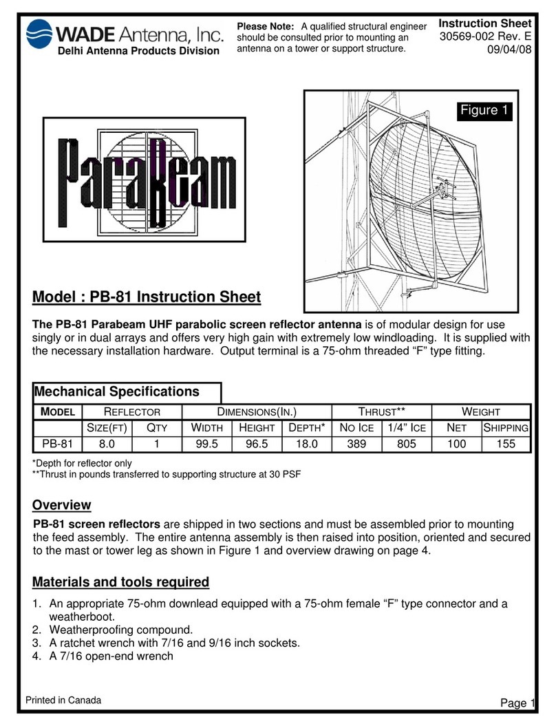
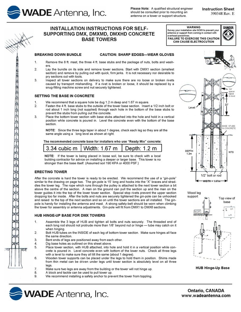
WADE Antenna, Inc. Taco Antenna D4000 Series User manual

TACO
Antenna
A division of WADE Antenna, Inc.
D4000/D5000 SERIES
OMNI-DIRECTIONAL
VHF/UHF Antennas
INSTRUCTION BOOKLET

Instruction Booklet - D4000 and D5000 Series Omnidirectional 1
The TACO Model D4000 and D5000 series antennas are vertically polarized
omnidirectional antennas, specically designed to provide optimum
performance throughout the DOT/FAA frequency band ranging 118-136
MHz and 225-400 MHz. The internal elements or dipoles are enclosed in a
berglass radome, ultimately resulting in a lightweight, low prole, rugged
communications antenna.
The D4000 or 5000 series antenna mounts to the top of the mast, thus
sheltering the transmission line from any environmental exposure. Some
D4000 series models are also available with an adapter capable of
mounting to a 1.66” O.D. mast.
General Description
The process employed in a D4000 or D5000 series antenna incorporates
the patented MuldipolTM concept. The utilization of this technique results
in a unit having excellent “broadband” halfwave dipole characteristics over
its entire specied frequency bandwidth. The desired “gure eight”
radiation pattern is generally constant throughout the band. Through
“broadband” suppression of extraneous currents upon the transmission
line, the undesirable “Clover Leaf” pattern is avoided.
A grounding lug is provided at the base of each antenna for supplemental
grounding capability.
Theory of Operation
Tested Polarization:
Brantford, Ont., Can., N3T 5L8
www.wadeantenna.com
-3dB Beam width: 75
VERTICAL
29 Sharp Rd, Box 1206
Freguency Range: 118 - 136 MHz
Maximum Gain: 2
Azimuth Pattern 5-Oct-09
Antenna Model: D5076
0510 15 20
30
25
35
40
45
50
55
60
65
70
75
80
85
95
100
105
110
115
120
125
130
135
140
145
150
155
160
170 165
175
180
185
210
190
205
200 195
250
215
235
240
245
230
225
220
255
260
265
275
280
285
300
295
290
315
310
305
325
330
355
340
320
350
335
345
270 90
MODEL D5076

Instruction Booklet - D4000 and D5000 Series Omnidirectional
2
VHF FREQUENCIES ONLY
MODEL # OF
OUTPUTS
FREQUENCY
RANGE
(MHz)
GAIN
(dBic
Max)
HPBW
DEGREE
TERMINAL:
TYPE AND
QUANTITY
LENGTH WEIGHT
MOUNT #
IN CM LBS KG
D4061A1 1 118-136 4.5 40 N1 121.5 308.6 19.0 8.62 1
D4072 2 118-136 2.0 75 N2 153.0 388.6 17.0 7.73 1
D4076 1 118-136 2.0 75 N1 55.5 141.0 6.0 2.72 2
D5061A1 1 118-136 4.5 40 N1 121.5 308.6 19.0 8.62 1
D5072 2 118-136 2.0 75 N2 153.0 388.6 17.0 7.71 1
D5076 1 118-136 2.0 75 N1 55.5 141.0 6.0 2.72 2
D5075 1 150-175 2.0 75 N1 56.0 142.2 6.0 2.72 2
UHF FREQUENCIES ONLY
MODEL # OF
OUTPUTS
FREQUENCY
RANGE
(MHz)
GAIN
(dBic
Max)
HPBW
DEGREE
TERMINAL:
TYPE AND
QUANTITY
LENGTH WEIGHT
MOUNT #
IN CM LBS KG
D4062A 1225-400 4.5 40 N1 69.5 176.5 13.5 6.12 2
D4074 2225-400 2.0 75 N2 85.0 215.9 12.0 5.44 1
D4077 1225-400 2.0 75 N1 30.5 77.5 5.0 2.27 2
D4078 3225-400 2.0 75 N3 121.5 308.6 17.0 7.71 1
D5062A 1225-400 4.5 40 N1 69.5 176.5 13.5 6.12 2
D5074 2225-400 2.0 75 N2 85.0 215.9 12.0 5.44 1
D5077 1225-400 2.0 75 N1 30.5 77.5 5.0 2.27 2
D5078 3225-400 2.0 75 N3 121.5 308.6 17.0 7.71 1
VHF AND UHF FREQUENCIES
MODEL
# OF
OUTPUTS FREQUENCY
RANGE
(MHz)
GAIN
(dBic
Max)
HPBW
DEGREE
TERMINAL:
TYPE AND
QUANTITY
LENGTH WEIGHT
MOUNT #
VHF UHF IN CM LBS KG
D4071 1 2 118-136 / 225-400 2.0 75 N3 111.5 283.2 17.0 7.71 1
D4073 1 1 118-136 / 225-400 2.0 75 N2 85.0 215.9 12.0 5.44 1
D5071 1 2 118-136 / 225-400 2.0 75 N3 111.5 283.2 17.0 7.71 1
D5073 1 1 118-136 / 225-400 2.0 75 N2 85.0 215.9 12.0 5.44 1
MOUNT NUM. DIAMETERS
(1) = 2.875 inch (7.3 cm) O.D. Pipe
(2) = 2.875 inch (7.3cm) O.D. Pipe and also
includes adapter for 1.66 (4.2cm) O.D. Pipe
D4000 series only
NOTE:
Use model numbers above disregarding trailing
sufxes other than those listed above, should there
be any in your antenna model number.
Specications

Instruction Booklet - D4000 and D5000 Series Omnidirectional 3
ASSEMBLY
1. Loosen the clamping screws on the antenna. See mounting detail.
2. Pull downleads up through the mounting pipe and make the
connection to the antenna.
3. If grounding your equipment, do so at this time by following
the Safety Precautions procedure.
4. Slide the clamping end of the antenna onto the mounting pipe.
5. Alternately secure the clamping screws making sure to keep the
mounting pipe centred with the antenna.
6. After final tightening, lock clamping screws into position using the
supplied stainless steel hex nuts.
ANTENNA
(5000 Series shown)
CLAMPING SCREW
MOUNTING PIPE(MAST)
ANTENNAASSEMBLY
MOUNTING DETAIL
(4000 Series shown)
CLAMPING
SCREW
MOUNTING PIPE
(MAST)
GROUND WIRE
S.S. LOCK NUT
ANTENNA
DOWNLEADS
CENTER (VHF)
GROUND LUG
(4000 SERIES ONLY)
LOWER (UHF)
UPPER (UHF)
4 5
ANTENNA ASSEMBLY
Loosen the clamping screws on the antenna. See mounting detail.1.
Pull downleads up through the mounting pipe and make the 2.
connection to the antenna.
If grounding your equipment, do so at this time by following the Safety 3.
Precautions procedure.
Slide the clamping end of the antenna onto the mounting pipe.4.
Alternately secure the clamping screws making sure to keep the 5.
mounting pipe centred with the antenna.
After nal tightening, lock clamping screws into position using the 6.
supplied stainless steel hex nuts.
Assembly

Instruction Booklet - D4000 and D5000 Series Omnidirectional
4
ASSEMBLY
1. Loosen the clamping screws on the antenna. See mounting detail.
2. Pull downleads up through the mounting pipe and make the
connection to the antenna.
3. If grounding your equipment, do so at this time by following
the Safety Precautions procedure.
4. Slide the clamping end of the antenna onto the mounting pipe.
5. Alternately secure the clamping screws making sure to keep the
mounting pipe centred with the antenna.
6. After final tightening, lock clamping screws into position using the
supplied stainless steel hex nuts.
ANTENNA
(5000 Series shown)
CLAMPING SCREW
MOUNTING PIPE(MAST)
ANTENNAASSEMBLY
MOUNTING DETAIL
(4000 Series shown)
CLAMPING
SCREW
MOUNTING PIPE
(MAST)
GROUND WIRE
S.S. LOCK NUT
ANTENNA
DOWNLEADS
CENTER (VHF)
GROUND LUG
(4000 SERIES ONLY)
LOWER (UHF)
UPPER (UHF)
4 5
MOUNTING DETAIL
(4000 SERIES SHOWN)

Instruction Booklet - D4000 and D5000 Series Omnidirectional 5
GROUNDING DETAIL
(FOR 5000 SERIES ONLY)
To protect your antenna and receiver from lightning damage, you should
ground your equipment.
Slide the ground wire (#6 recommended) into the ground lug as shown 1.
below and tighten the #10-32 x 3/8 set screw.
Connect the ground wire to a ground rod; driven at least four (4) feet 2.
into the ground.
Keep antenna and cable a safe distance from any power lines.3.
Safety Precautions
SAFETY PRECAUTIONS
To protect your antenna and receiver from lightning damage, you should
ground your equipement.
1. Slide the ground wire (#6 recommended) into the ground lug as shown
below and tighten the #10-32 x 3/8 set screw.
2. Connect the ground wire to a ground rod; driven at least four (4)
feet into the ground.
3. Keep antenna and cable a safe distance from any power lines.
ANTENNA CLAMP
#10-32 SET SCREW
MOUNTING PIPE
GROUND WIRE (#6)
GROUNDING DETAIL
FOR 5000
SERIES ONLY
MOUNT NUM. DIAMETERS
(1) = 2.875 inch (7.3 cm) O.D. Pipe
(2) = 2.875 inch (7.3 cm) O.D. Pipe. to 1.9 in. (4.826 cm) O.D. pipe
6 3
in. cm. lbs. kg.
40 N1 121.5 308.6 19.0 8.62 1
40 N1 69.5 176.5 13.5 6.14 1
40 N1 72.0 182.9 14.5 6.59 1
75 N3 111.5 283.2 16.8 7.62 1
75 N3 119.5 303.5 17.5 7.95 1
75 N2 153.0 388.6 18.0 8.16 1
75 N2 158.0 401.3 17.5 7.95 1
75 N2 85.0 215.9 12.0 5.44 1
75 N2 90.0 228.6 12.5 5.67 1
75 N2 85.0 215.9 12.0 5.44 1
75 N2 90.0 228.6 12.5 5.67 1
75 N1 55.5 141.0 6.0 2.72 1
75 N1 30.5 77.5 4.9 2.22 1
75 N3 127.0 322.6 17.5 7.94 1
40 N1 121.5 308.6 19.0 8.64 1
40 N1 69.5 176.5 13.5 6.14 2
75 N3 111.5 283.2 16.8 7.63 1
75 N2 153.0 388.6 18.0 8.16 1
75 N2 85.0 215.9 12.0 5.44 2
75 N1 55.5 141.0 6.0 2.72 2
75 N1 30.5 77.5 4.8 2.15 2
75 N3 121.5 308.6 16.8 7.63 1
MOUNT
#
HPBW
DEGREE
TERMINAL:
Type And
Quantit
y
HEIGHT WEIGHT

Instruction Booklet - D4000 and D5000 Series Omnidirectional
6
30 dB Minimum Isolation Between Any Two Dipoles•
Vertical Polarization•
Omni Directional: 0.5 dB Uniformity (azimuth)•
Voltage Standing Wave Ratio (Max.) 2:1•
Terminals “N” Female•
Terminal Impedance 50 Ohms•
VHF Applied Power 350 W•
UHF Applied Power 250 W•
Vertical Beam Deviation +- 10 Deg.•
Typical Specications
ELECTRICAL
Built to Military Standards•
Rain, salt-fog, sand, dust and fungus to MIL-STD.810F•
Temperature, barometric pressure and humidity to MIL-STD.210C•
Temperature: -50°C to +70°C•
Relative Humidity: 5% to 100%•
Altitude: Sea Level To 10,000 ft. (3,048 m)•
Filament Wound Fiberglass Radome•
ENVIRONMENTAL
Rugged Lightweight Construction•
Transportable•
Compact•
Combination of UHF and VHF options•
High isolation between antenna elements•
Features
Lightning Rod ( L)•
Bird Cap (BC)•
Aluminum Base (A)•
Frequency Alteration (F)•
Carc (C), White (W), Green (G), Desert Sand (D)•
Obstruction Light / Lightning Rod (OL)•
Options and Acronyms
Contact our sales representatives or consult our sales specication
sheet to nd out if these options are available for your application.

Instruction Booklet - D4000 and D5000 Series Omnidirectional 7
GENERAL DESCRIPTION
The TACO Model D4000 and D5000 series antennas are vertically
polarized omnidirectional antennas, specifically designed to provide
optimum performance throughout the DOT/FAA frequency band ranging
118-136 MHz and 225-400 MHz. The internal elements or dipoles are
enclosed in a fiberglass radome, ultimately resulting in a lightweight, low
profile, rugged communications antenna.
The D4000 or D5000 series antenna you have purchased, comes with a
built in clamping arrangement accommodating a 2.50 in (6.35 cm) IPS
mast. Some models are also available with an adapter capable of mounting
to a 1.25in. (3.175 cm) IPS mast. The built in clamp arrangement allows
for inline mounting of the antenna with the mast, thus sheltering the
transmission line from any environmental exposure.
THEORY OF OPERATION
The process employed in a D4000 or D5000 series antenna, incorporates
the patented Muldipoltm concept. The utilization of this technique results in
a unit having excellent “broadband” halfwave dipole characteristics over
its entire specified frequency bandwidth. The desired “figure eight”
radiation pattern is generally constant throughout the band. Through
“broadband” suppression of extraneous currents upon the transmission
line, the undesirable “Clover Leaf” pattern is avoided.
A grounding lug is provided at the base of each antenna for supplemental
grounding capability.
OBSTRUCTION LAMP DETAIL
LENS (RED)
CLAMPING RING SCREW
CLAMP
LENS SAFETY CHAIN
CLAMPING RING
ANTENNA
OBSTRUCTION LIGHT ASSEMBLY-E
1. Install supplied light bulb (100 Watt, 130 Volts industrial) in lamp
socket.
2. Remove one screw on the clamping ring and open it to slide onto the
bottom of the lens; close the ring on the bottom groove of the lens and
reinstall the screw.
3. Place the lens on the lamp, as shown below, and clamp down using the
lamp clamps.
8 1
OBSTRUCTION LAMP DETAIL
Install supplied light bulb (100 Watt, 130 Volts industrial) in lamp 1.
socket.
Remove one screw on the clamping ring and open it to slide onto the
2.
bottom of the lens; close the ring on the bottom groove of the lens and
reinstall the screw.
Place the lens on the lamp, as shown below, and clamp down using 3.
the lamp clamps.
Obstruction Light Assembly-E

Instruction Booklet - D4000 and D5000 Series Omnidirectional
8
To obtain replacement parts, please contact us directly at our ofces at:
Canada: Tel: (519) 756-7157 | (800) 463-1607
Fax: (519) 756-5056
USA/International: Tel: (717) 975-0885 | (866) 975-4433
Fax: (717) 763-0469
Email: [email protected]
www.tacoantenna.com
Replacement Parts
Other Communications Antennas
I]ZI68DX^gXjaVganedaVg^oZY]Za^XVaVciZccVh
Vg ZZmi gZb Za n gj\ \Z YV cY YZ h^ \c ZY id de Zg ViZ
jc YZgi ]Z hZ kZg Zh i d[ Zc k^g dc bZc iV a Xdc Y^ i^d ch #
I]Z b Vh iV cY \g dj cY ea Vc ZV gZ d[ V ajb ^c jb
Xd chigj Xi ^dc l ^i] i ]Z ]Z a^ mh je edg iZ YW n
Y^ ZaZXi g^ Xg dY hV ad c\ i] Z bVh i# I] Z\ gd jc Ye aV cZ
d[i]Z&%-"(&*B=obdYZah^hXdchigjXiZY
l^ i]i] Z \gd jc Ye aV cZ WV X`Z Y l^ i] gZ ^c[ dg X^c \
g^ Wh^c id l] ^X ]i jW jaV g Vm ^Va g dYh V gZ ea VX ZY id
^c XgZVh Z i]Z Y ^Vb Zi Zg d[ i ]Z \g djc Y eaV cZ
I68 DÉh hZ Xi ^dc Va ]Z a^ XV a^ h YZg ^k ZY [g db i] Z
hi VcYVg Y ]Za ^X Va a^ cZ [d g Vee a^ XVi ^d ch YZ bV cY^ c\
V ]^\] YZ \gZ Z d[ ig Vch ed gi VW^ a^ in Vc Yb Vn WZ
jh ZYh^ c\ an dg ^c b jai ^e aZ Vg gV nh# I] Z Vci Zc cV
Xd ch^hi h d[ V ]^c \Z Y! [d aY ^c\ \ gdj cY "ea Vc Z
Vc Ybja i^ eaZ ] Za^ m ZaZ bZ ci hl ]^ X] XV cW Z
Vh hZbWa ZY fj ^X `an#
Bd hibd YZ ah Vk V^a VW aZ ^c hZ Xi ^d cVa
Xd chigj Xi ^dc #
Ea ZVhZ Xd ciV Xi hV aZ h#
9_hYkbWhboFebWh_p[Z7dj[ddWi
I[Yj_edWb7dj[ddWEfj_ed
L > < W d Z K > <
> [ b _ Y W b 7 d j [ d d W i
I68D6ciZccVÉhdc\d^c\eda^Xnd[Xdci^cj^c\YZkZadebZcibVngZhjai^cheZX^[^XVi^dcX]Vc\Zhid^ihegdYjXih#
KI7D:?DJ;HD7J?ED7BI7B;I
I68 D 6c iZ cc V
6 Y^k h^ dc d[ LV YZ 6ci Zc cV! > cX#
(/ I ^W hf He WZ "
8h Wd j\ ehZ " Ed jW h_e " D) J +B. " 9W dW ZW
J[b 0 +' /$- +, $- '+ -e h .& &$ *, )$' ,& -
<W n0 +' /$ -+ ,$ +&+ ,
YW di Wb [i6 jW Ye Ye cck d_ YW j_ edi $Y ec
I68 D 6c iZ cc V
6 Y^k h^ dc d[ LV YZ 6ci Zc cV! > cX#
++ '( 8 [Wh Yh [[ a :h_ l[ "
C[ Y^ Wd _Yi Xk h] " F7 '- &+&
J[b 0 -' -$/ -+ $& .. +e h ., ,$ /- +$* *) ) <W n0 - '- $-, )$ &* ,/
;c W_ b0 iW b[ i6 jW YeY ec ck d_ YWj _e di $Y ec
M[ XI _j [0 m mm$ jW Ye Yec ck d_ YW j_e di $Y ec
97D7:?7DI7B;I
J7 9 E
6 c i Z c c V
6Y^k^h^dcd[L69:6ciZccV!>cX#
I]^h Vc iZ cc Vegd k^ YZ hl^Y Z WV cY K= ;$ J= ; [gZfj Zc X^ Zh
Xd bW ^cZY ^c id V h^c\ aZ d ji eji[ dg j hZ gh^c b Vg ^i ^bZ !
aV cY bdW^ aZ V cY iVXi ^X Va a ^cZ"d [" h^ \] iXdb bj c^ XV i^d ch #
>i^hVahdZ[[ZXi^kZ[dgX^k^a^VcVcYb^a^iVgnV^gigV[ÒX
Xd ci gdad eZ gV i^ dch#
9 j V a ; g Z f j Z c X n
H ^ c \ a Z D j i e j i B j a Y ^ e d a
I68D6ciZccVÉhdc\d^c\eda^Xnd[Xdci^cj^c\YZkZadebZcibVngZhjai^cheZX^[^XVi^dcX]Vc\Zhid^ihegdYjXih#
KI7D:?DJ;HD7J?ED7BI7B;I 97D7:?7DI7B;I
I68 D 6c iZ cc V
6 Y^k h^ dc d[ LV YZ 6ci Zc cV! > cX#
(/ I ^W hf He WZ "
8h Wd j\ ehZ " Ed jW h_e " D) J +B. " 9W dW ZW
J[b 0 +' /$- +, $- '+ -e h .& &$ *, )$' ,& -
<W n0 +' /$ -+ ,$ +&+ ,
YW di Wb [i6 jW Ye Ye cck d_ YW j_ edi $Y ec
I68 D 6c iZ cc V
6 Y^k h^ dc d[ LV YZ 6ci Zc cV! > cX#
++ '( 8 [Wh Yh [[ a :h_ l[ "
C[ Y^ Wd _Yi Xk h] " F7 '- &+&
J[b 0 -' -$/ -+ $& .. +e h ., ,$ /- +$* *) ) <W n0 - '- $-, )$ &* ,/
;c W_ b0 iW b[ i6 jW YeY ec ck d_ YWj _e di $Y ec
M[ XI _j [0 m mm$ jW Ye Yec ck d_ YW j_e di $Y ec
J 7 9E
6 c i Z c c V
6Y^k^h^dcd[L69:6ciZccV!>cX#
H e Z X ^ Ò X V i ^ d c h
GV ^c! hVa i! [d\ !h VcY !Y jhi Vc Y[ jc\ jh id B>A" HI9 "
-& %6 VcY 7#
IZbe ZgV ijg Z! 7Vg dbZ ig^ XE gZh hjg ZV cY =jb ^Y^ in
id B> A"HI9 "'& %V cY '&% 6
:A:8IG>86A
B d Y Z a 9 ' ' & &
TACO Dual Frequency,
Single Output Muldipol
Model D2211
This antenna provides wide band VHF/UHF
frequencies combined into a single output
for users in maritime, land mobile and
tactical line-of-sight communications. It is
also effective for civilian and military air
traffic control operations.
Electrical Specifications
Module VHF UHF
Frequency Range 108-174 MHz 225-400 MHz
Gain (dBi @ FC) (+0) (+0)
VSWR (Typical) 2:1 2:1
VSWR (max) 2.3:1 2.3:1
Polarization Vertical Vertical
HPBW (Vertical deg. Nom.) 75 (centered on horizon) 75 (centered on horizon)
Omni directional Uniformity +/-0.5 dB (Azimuth) +/-0.5 dB (Azimuth)
Isolation (Min. dB) 35 35
Impedance 50 Ohms
Terminal Type N Female
Vertical Beam-Center Deviation + or –10 degrees (from horizon)
Applied Power 100 Watts Max
Mechanical Specifications
Height 111 in (281.9 cm)
Weight 14 lbs (6.4kg)
Mount (Mast Diameter) 3 in (7.62 cm)
Wind Load Area No Ice 1.5 sq ft
Wind Load Area 1/2 in Ice 2.0 sq ft
Environmental Specifications
Rain, salt, fog, sand, dust and fungus to MIL-STD-810A and B.
Temperature, Barometric Pressure and Humidity to MIL-STD-210 and 210A
Radome Material Filament Wound Fiberglass
Diameter 2.85 in O.D. (7.24 cm)
Color White or Green
TACO Communications Inc.
29 Sharp Road,
Brantford, Ontario, Canada
N3T 5L8
Tel: 800.463.1607 Fax: 866.596.6600
Web Site: www.tacocommunications.com
TACOCommunications’ ongoing policy of continuing development may result in specification changes to its products.
Module VHF UHF
Frequency Range 108-174 MHz 225-400 MHz
Gain (dBi @ FC) (+0) (+0)
VSWR (Typical) 2:1 2:1
VSWR (max) 2.3:1 2.3:1
Polarization Vertical Vertical
HPBW (Vertical deg. Nom.) 75 (centered on
horizon)
75 (centered on
horizon)
Omni directional Uniformity +/-0.5 dB (Azimuth) +/-0.5 dB (Azi-
muth)
Isolation (Min. dB) 35 35
Impedance 50 Ohms
TerminalType N Female
Vertical Beam-Center Deviation + or –10 degrees
(from horizon)
Applied Power 100 Watts Max
B:8 =6C>86A
Module VHF
Height 111 in (281.9 cm)
Weight 14 lbs (6.4kg)
Mount (Mast Diameter) 3 in (7.62 cm)
Wind Load Area No Ice 1.5 sq ft
Wind Load Area 1/2 in Ice 2.0 sq ft
:CK >GDCB:CI6A
Module VHF
Radome Material Filament Wound Fiberglass
Diameter 2.85 in O.D. (7.24 cm)
Color White or Green
Hj gk^ kVa G Vi^ c\ &*% B #E#=# BVm ^bj b L^c YH eZZ YV i hZV aZ kZa l^ i] Dc Z= jc YgZ Y
EZg XZc i =jb ^Y^ in Vi HZ kZc in 9Z \gZ Zh ;V] gZc ]Z ^i# HV [Zi n [VX idg d[ & #+* ^c Xa jYZ Y#
I68D6ciZccVÉhdc\d^c\eda^Xnd[Xdci^cj^c\YZkZadebZcibVngZhjai^cheZX^[^XVi^dcX]Vc\Zhid^ihegdYjXih#
I]Z ;& & Vc Y 6 H"( .% 6$H G8 V gZ kZg i^ XVa an e da Vg^ oZ Y Wg dV YWV cY XdV m^V a h ijW
Vc iZc cV hYZ h^ \cZ Y[ dg i]Z K= ;V cYJ =; Xd bbj c^ XVi ^dc hW Vc Y#7 di ]] VkZ WZZ c
YZ h^ \c ZY id l^ i] hiV cY i] Z b dh i h Zk Zg Z l ZV i] Zg X dc Y^ i^ dc h# 7d i] i] Z ; && Vc Y
6H "(. %6 $HG 8 bd YZa h Vg Z YZh ^\c ZY [ dg h] ^e WdV gY V eea ^X Vi^ dc h VcY e gZ hhj g^o ZY
l^ i] V kVa jZ Ò ii^ c\ [ dg V lVi Zgi ^\] i hZ Va# I]Z V ciZ ccV h bd jci id V i]g ZVY ZY
e^ eZ # I6 8D 8 dV m" H ij W V ci Z cc Vh Vg Z Va hd Vk V ^a VW aZ c dc "e gZ h hj g^ o ZY l^ i] J "W da i
bd jci h bd YZ ah ;& &"C EV cY 6H "( .% #
HE:8>;>86I>DCH
8D 6 M " H IJ 7 6 C I : C C 6
< ' ' W d Z 7 I # ) / & 7 % I H 9
BD 9:A
;G :FJ :C8 NG6 C<:
<6>C Y7^
KH LG CDB#
EDA6G> O6I>D C
8GDH H EDA G:? :8I> DC
=D G>OD CI6A E 6 II: GC
K: GI> 8 6 A E 6 II :GC
>BE:96 C8:
I: GB> C6A INE:
ED L:G G6I>C <
DE:G6 I>C< I:B E:G6IJ G:
;& & K=;
&% -"& ,) B=o
'# % % $ "&
JcYZ g '/&
KZg i^ XVa
'% Y7
Dbc^ 9^g ZX i^d cVa l^ i] ^c %#* Y7
.* ¥ &* YZ eZc Y^c \ dc [gZ fjZ cXn
*% D]b h
C;Z bVa Z
)% %L Vii hV i& ,% B=o
*% %L Vii hV i& (' B=o
") %8 id -% 8
" )% ;i d &,+ ;
:A:8IG>86A
6H "(. %6$ HG 8 J=;
'' *") %% B=o
'# % % $ "&
JcYZ g '/&
KZg i^ XVa
'% Y7
Dbc^ 9^g ZX i^d cVa l^ i] ^c %#* Y7
.* ¥ &* YZ eZc Y^c \ dc [gZ fjZ cXn
*% D]b h
C;Z bVa Z
'% %L Vii hV i) %% B=o
") %8 id -% 8
" )% ;i d &,+ ;
BD 9:A
DK : G6 AA =:> <=I
HIJ7=: ><= I
H@ >GI9>6 B:I: G
L: ><= I
;& & K=;
)% ^c X]Z h
'' #(, *^ cX ]Zh
)( ^c X]Z h
+# '' aWh
B:8=6C>86A
6H "(. %6$ HG 8 J=;
&+ ^c X]Z h
.# +'* ^c X] Zh
'( ^c X]Z h
(# ,* aWh
6CI:CC6E6II:GCH
;&&"INE>86A="EA6C:
;&&"INE>86A:"EA6C:
BD 9:A
L> C9 6G: 6 C D>8 :
& $'Ç G6 9> 6A> 8:
L> C9 AD 6 9 CD >8:
&$ 'Ç G6 9>6A >8 :
HJ GK> K6A G6 I >C <
CD >8:
;& & K=;
%# ). HF; I
&# &) HF; I
'. #* ;I" A7H
&. #, ;I" A7H
(( *B# E#=#
L>C9AD 69>C<
6H "(. %6$ HG 8 J=;
%# '% HF; I
%# ), HF; I
+# %; I"A 7H
)# &; I"A 7H
*( %B# E#=#
L^c YHe ZZY 2 &%% BE =V ihZ Va ZkZ al ^i] &%% = jb^Y ^in Vi ,% ; V]gZ c]Z ^i#
L^ cYH eZZ Y 2*% BE =V ihZ Va ZkZ al ^i] &%% = jb^Y ^in Vi % ;V ]gZc ]Z^ i#
B Vm^b jb L^cY HeZ ZY Vi hZV aZkZ al ^i] &%% =j b^Y^ inV i, % ;V] gZc] Z^i #HV [Zin ;V Xid gd[ &# +* ^cXa jYZ Y#
J 7 9 E
6 c i Z c c V
6Y^k^h^dcd[L69:6ciZccV!>cX#
KI7D:?DJ;HD7J?ED7BI7B;I7=;DJ 97D7:?7DI7B;IE<<?9;
I68 D 6c iZ cc V
6 Y^k h^ dc d[ LV YZ 6ci Zc cV! > cX#
(/ I ^W hf He WZ "
8h Wd j\ ehZ " Ed jW h_e " D) J +B. " 9W dW ZW
J[b 0 +' /$- +, $- '+ -
<W n0 +' /$ -+ ,$ +&+ ,
YW di Wb [i6 jW Ye Wd j[d dW $Y ec
I68 D 6c iZ cc V HV aZ h GZ e
J[b 0 -' -$/ -+ $& .. +
Jeb b <h[ [0 . ,, $/- +$ ** ))
<W n0 -' -$ -, )$ &*, /
;c W_ b0 iW b[ i6 jW YeW dj [d dW $Ye c
M[ XI _j [0 m mm$ jW Ye Wdj [d dW $Y ec
Coax Stub•
Helical•
Yagi•
Screen Reector Yagi•
D2000 Muldipol•
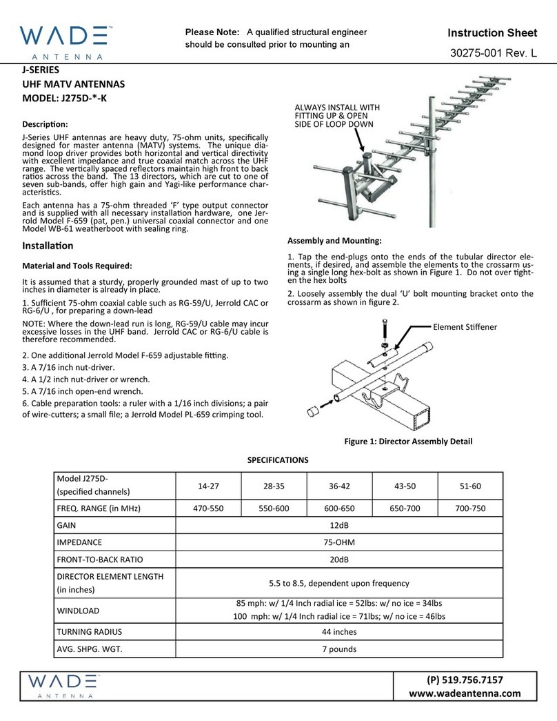
This manual suits for next models
20
Table of contents
Other WADE Antenna, Inc. Antenna manuals

WADE Antenna, Inc.
WADE Antenna, Inc. J275D-*-K User manual

WADE Antenna, Inc.
WADE Antenna, Inc. DMX, DMXMD, DMXHD User manual

WADE Antenna, Inc.
WADE Antenna, Inc. J55-2 User manual

WADE Antenna, Inc.
WADE Antenna, Inc. PB-81 User manual

WADE Antenna, Inc.
WADE Antenna, Inc. J-283X User manual

WADE Antenna, Inc.
WADE Antenna, Inc. D-1338BB User manual