1
INTRODUCTION
The Clipper Compass is supplied complete with display unit, sensor unit, and
Mounting kit. It is designed to operate from the vessel’s 12V battery supply.
PRE-TEST OF INSTRUMENT
Before mounting the units, check that the instrument is complete and undamaged.
Connect the sensor unit to the display unit and apply 12 volts. Confirm that a reading
is shown on the display.
INSTALLATION OF SENSOR
The sensor measures the direction of the Earth’s weak magnetic field, and so is
sensitive to other magnetic fields which can affect the unit’s accuracy. It should
therefore be positioned carefully. Select a sensor position as far as possible away from large
ferrous objects such as engines, and items such as DC motors or loudspeakers which
have powerful permanent magnets in them. Check also for small ferrous objects close
to the mounting location such as screws, nails, hinges etc. These can become
magnetised and cause errors. When a likely location has been found, a check for
reasonable accuracy can be made with a hand bearing compass to confirm its
suitability.
The magnetic sensor itself is gimballed within the housing. To accommodate pitch
and roll motions most effectively, mount the sensor as near to horizontal as possible.
For best performance in rough weather conditions, it is also advisable to mount the
sensor in a position (usually amidships) that minimises lateral accelerations due to
pitch and roll. Avoid mounting the sensor high above the water line because doing so
also increases pitch and roll accelerations. The sensor is waterproof to CFR-46
standard. Ensure the sensor does not become submerged.
Position the sensor unit and mark and drill pilot holes for mounting screws to allow the
sensor to be rotated to align it exactly with the vessel’s axis. Now mount the sensor
carefully in position using non-magnetic screws. The rotational position of the sensor
should be chosen to ensure that the arrow points as close as possible fore-and-aft.
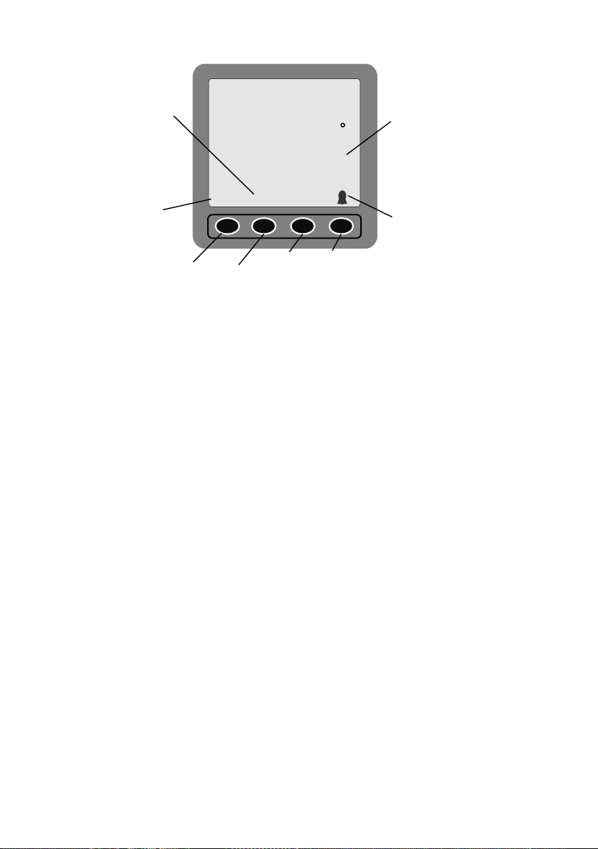
INSTALLING THE DISPLAY
Select a convenient position for the display on a panel or bulk-head. The site must be
flat and the cavity behind the panel must remain dry at all times. (The cable entry is
deliberately not sealed to ensure adequate ventilation. This prevents misting of the
display).
Cut a hole in the panel 67mm high and 87mm wide. Bring the wiring through the hole
in the panel and connect as shown on Figure 1. It is wise to use a fused supply to
provide protection should a fault occur. The current consumption is very small, so any
supply with a ¼-Amp fuse is more than adequate.
Unscrew and remove the wing nut from the rear of the instrument and remove
the stainless steel clamping bracket. Fit the “O” ring seal into the groove in the panel
mounting face of the instrument. Ensure that it is correctly lying in its groove before
fitting the instrument to the panel, which provides the watertight seal for the display.