NASAB power 1000 User manual

GARAGE DOOR OPENER
INSTALLATION MANUAL
Please read the manual and the enclosed
safety materials carefully!
Fasten the manual near the garage door after
installation.
Periodic checks of the opener are required to
ensure safe operation.
The model number label is located on the left
side panel of your opener.
MEN -002-B
GARAGE DOOR OPENER
INSTALLATION MANUAL
Please read the manual and the enclosed safety materials
carefully!
Fasten the manual near the garage door after installation.
Periodic checks of the opener are required to ensure safe
operation.
The model number label islocated on the left side panel
of your opener.

2
TABLE OF CONTENTS
INTRODUCTION....................................................................3
Tools needed........................................................................5
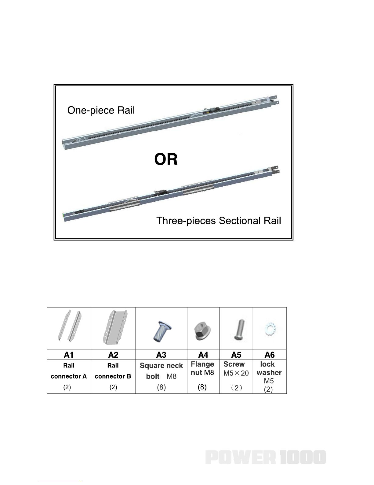
Assemble the Rail................................................................6
Garage door opener assembly.........................................10
Hardware..............................................................................10
Fasten the Rail to the garage door opener......................12
Determine the Header Bracket Location...........................13
Install the Header Bracket...................................................15
Connect the Rail to the Header Bracket..............................17
Position the garage door opener..........................................18
Hang the garage door opener............................................19
Attach the Emergency Release Rope and Handle...............20
Install the door bracket.......................................................21
Connect the door arm to the trolley.....................................23
Install the Wall Control.....................................................25
Attach the Warning Labels...............................................28
Install The Photo Eye Safety System............................29
Power and adjustments...................................................33
Programming and adjustment..........................................34
Programming buttons...........................................................34
Preparation...........................................................................34
Connect Power.....................................................................34
Program the travel................................................................35
Remote Control....................................................................36
To Erase the Memory...........................................................37
The adjustment of reverse force.........................................38
Circuit board.........................................................................40
Use photoelectric switches...................................................41
Turn off light automatically...............................................42
Power failure clutch lock...................................................42
Backup battery..................................................................42
Door within a Door...........................................................43
Maintenance and repair.....................................................43
Technical parameter..........................................................43
Trouble shooting................................................................44

3
INTRODUCTION
Safety Symbol and Signal Word Review
This garage door opener has been designed and tested to offer
safe service provided it is installed, operated, maintained and
tested in strict accordance with the instructions and warnings
contained in this manual. When you see these Safety Symbols and
Signal Words on the following pages, they will alert you to the
possibility of serious injury or death if you do not comply with the
warnings that accompany them.
The hazard may come from something or from electric shock. Read
the warnings carefully.
When you see this Signal Word on the following pages, it will alert
you to the possibility of damage to your garage door and/or the
garage door opener if you do not comply with the cautionary
statements that accompany it. Read them carefully.
Check your garage door
1. Disable locks and remove any ropes connected to the
garage door.
2. Lift the door halfway up. Release the door. If balanced, it
should stay in place, supported entirely by its springs.
3. Raise and lower the door to check for binding or sticking. If
your door binds, or is out of balance, call a trained door
systems technician.
4. Check the seal on the bottom of the door. Any gap
between the floor and the bottom of the door must not
exceed 1/4 inch (6 mm). Otherwise, the safety reversal
system may not work properly.

4
5. The opener should be installed above the center of the
door. If there is a torsion spring or center bearing plate in
the way of the header bracket, it may be installed within 4
feet (1.2 m) to the left or right of the door center. See
Installing the Header Bracket section.

5
Tools needed
During assembly, installation and adjustment of the opener,
instructions will call for hand tools as illustrated below.

6
1、Assemble the Rail
To avoid installation difficulties, do not run the garage door opener
until instructed to do so.
NOTE: If you choose the Three-pieces Sectional Rail, you may
need the following installation instructions.
Rail Accessories

7
Assemble the Rail

8
Assemble the Rail
1.1、Remove the three rail sections and place them on
1.2、Rail connectors installation.
1.3、Spread carefully the chain/belt straight inside the rail.
Check to be sure the chain is not twisted. Note: Make sure the
chain engage the 10-tooth sprocket as shown.
Rail Assembly
1.1、Remove the three rail sections and place them on
floor.
Seven holes rail
Center rail
1.2、Rail connectors installation.
1.3、Spread carefully the chain/belt straight inside the rail. Check
to be sure the chain is not twisted.
Note: Make sure the chain engage the 10-tooth sprocket as shown.
Three holes rail
A1
A2 A4
A3
6
Rail Assembly
1.1、Remove the three rail sections and place them on
floor.
Seven holes railCenter rail
1.2、Rail connectors installation.
1.3、Spread carefully the chain/belt straight inside the rail. Check
to be sure the chain is not twisted.
Note: Make sure the chain engage the 10-tooth sprocket as shown.
Three holes rail
A1
A2
A4
A3
6
Rail Assembly
1.1、Remove the three rail sections and place them on
floor.
Seven holes railCenter rail
1.2、Rail connectors installation.
1.3、Spread carefully the chain/belt straight inside the rail. Check
to be sure the chain is not twisted.
Note: Make sure the chain engage the 10-tooth sprocket as shown.
Three holes rail
A1
A2 A4
A3
6

9
Assemble the Rail
1.4 Screw and lock washer installation.
1.5、Tighten the Chain
1.5.1 To increase the tension and tighten the chain, turn the
tension nut clockwise or adjustable wrench until the nut is spaced
properly from the rail end -plate.
1.5.2 Once the nut is spaced correctly, any additional tightening will
over tighten the chain and may cause damage to the system.
1.5.3 To loose the tension, turn nut counterclockwise.
Note: the trolley should be away from locking holes.
Rail Assembly
1.4、Screw and lock washer installation.
Locking Holes
Note: the trolley should be away from locking holes.
A5(2)
A6(2)
25mm
1.5.1 To increase the tension and tighten the chain, turn the tension
nut clockwise or adjustable wrench until the nut is spaced
properly from the rail end -plate.
1.5.2 Once the nut is spaced correctly, any additional tightening will
over tighten the chain and may cause damage to the system.
1.5.3 To loose the tension, turn nut counterclockwise.
1.5、Tighten the Chain
7

10
Garage door opener assembly
Hardware

11
Garage door opener assembly

12
Garage door opener assembly
1、Fasten the Rail to the garage door opener
1.1 Place the opener on cardboard or protective surface on floor so
opener does not get scratched. Chassis side of opener is
facing up.
1.2 Position rail onto opener chassis by lining up rail sprocket,
Make sure shaft insert into rail sprocket. Press rail down firmly
onto shaft and opener chassis. DO NOT HAMMER.
1.3 Position 2 “U” rail clips over rail and onto chassis. Insert self-
threading screw (4) (H12) through rail clips holes and into
chassis holes. and tighten self-threading screws firmly to hold
rail to the garage door opener head.
Note: To avoid SERIOUS damage to garage door opener, use
ONLY those bolts/fasteners mounted in the top of the opener.

13
Garage door opener assembly
2、Determine the Header Bracket Location
Installation procedures vary according to garage door types. Follow
the instructions which apply to your door.
2.1 Close the door and mark the inside vertical centerline of the
garage door.
2.2 Extend the line onto the header wall above the door.
You can fasten the header bracket within 4 feet (1.22 m) of the
left or right of the door center only if a torsion spring or center
bearing plate is in the way; or you can attach it to the ceiling
when clearance is minimal. (It may be mounted on the wall
upside down if necessary, to gain approximately 1/2" (1 cm).
If you need to install the header bracket on a 2x4 (on wall or
ceiling), use lag screws (not provided) to securely fasten the 2x4 to
structural supports.
2.3 Open your door to the highest point of travel as shown. Draw
an intersecting horizontal line on the header wall above the high
point: 2" (5 cm) above the high point for sectional door with track.
NOTE: If the total number of inches exceeds the height available in
your garage, use the maximum height possible.

14
Garage door opener assembly

15
3、Install the Header Bracket You can attach the header bracket
either to the wall above the garage door, or to the ceiling. Follow
the instructions which will work best for your particular
requirements. Do not install the header bracket over drywall. If
installing into masonry, use concrete anchors (not provided).
Option A WALL INSTALLATION
3.1A Center the bracket on the vertical centerline with the bottom
edge of the bracket on the horizontal line as shown (with the arrow
pointing toward the ceiling).
3.2A Mark the holes. Drill 3/16" pilot holes and fasten the bracket
securely to a structural support with the hardware provided.

16
Option B CEILING INSTALLATION
3.1B Extend the vertical centerline onto the ceiling as shown.
3.2B Center the bracket on the vertical mark, no more than 6" (15
cm)
3.3B from the wall. Make sure the arrow is pointing away from the
wall. The bracket can be mounted flush against the ceiling when
clearance is minimal.
3.4B Mark the holes. Drill 3/16" pilot holes and fasten bracket
securely to a structural support with the hardware provided.

17
4、Connect the Rail to the Header Bracket
Align the rail to the header bracket, fasten with the bolts and nuts
(H1) (H2) as shown below.
HARDWARE
B5 Cotter Pin Φ2×25(1) B6 Shouldered shaft, long Φ8×80(1)

18
5、Position the garage door opener
NOTE: A 2x4 is ideal for setting the distance between the rail and
the door. If the ladder is not tall enough you will need help at this
point.
If the door hits the trolley when it is raised, pull the trolley release
arm down to disconnect the chain connector kit and trolley. Slide
the trolley toward the garage door opener. The trolley can remain
disconnected until further instruction.

19
6、Hang the garage door opener

20
7、Attach the Emergency Release Rope and Handle
NOTE: If it is necessary to cut the emergency release rope, seal
the cut end with a match or lighter to prevent unraveling. Ensure
that the emergency release rope and handle are above the top of
all vehicles to avoid entanglement.
7.1 Insert one end of the emergency release rope through the
handle. Tie a knot at least 1 inch (2.5 cm) from the end of the
emergency release rope.
7.2 Insert the other end of the emergency release rope through the
hole in the trolley release arm. Make sure the handle is 6 feet (1.83
m) above the floor and secure with a knot.
Table of contents
Other NASAB Garage Door Opener manuals
Popular Garage Door Opener manuals by other brands

Crawford
Crawford A-175 Assembly and user instructions

E.T. Systems
E.T. Systems Challenger MKIII Installer manual

Gliderol
Gliderol Glidermatic GRD installation instructions

Chamberlain
Chamberlain ATS 211 owner's manual

Xtreme Garage
Xtreme Garage 425-1671 owner's manual

Motostar
Motostar Stylstar installation manual

Craftsman
Craftsman 41A638-1 instructions

Craftsman
Craftsman 139.53930DM owner's manual

Craftsman
Craftsman 95355 - EntryEase Fingerprint Keyless Entry... user guide

Sears
Sears 139.53400 owner's manual

Merlin
Merlin commander myq MT110MYQ Installation and operating instructions

Chamberlain
Chamberlain 3280C 1/2 HP owner's manual