www.nassarelectronics.com 2
®
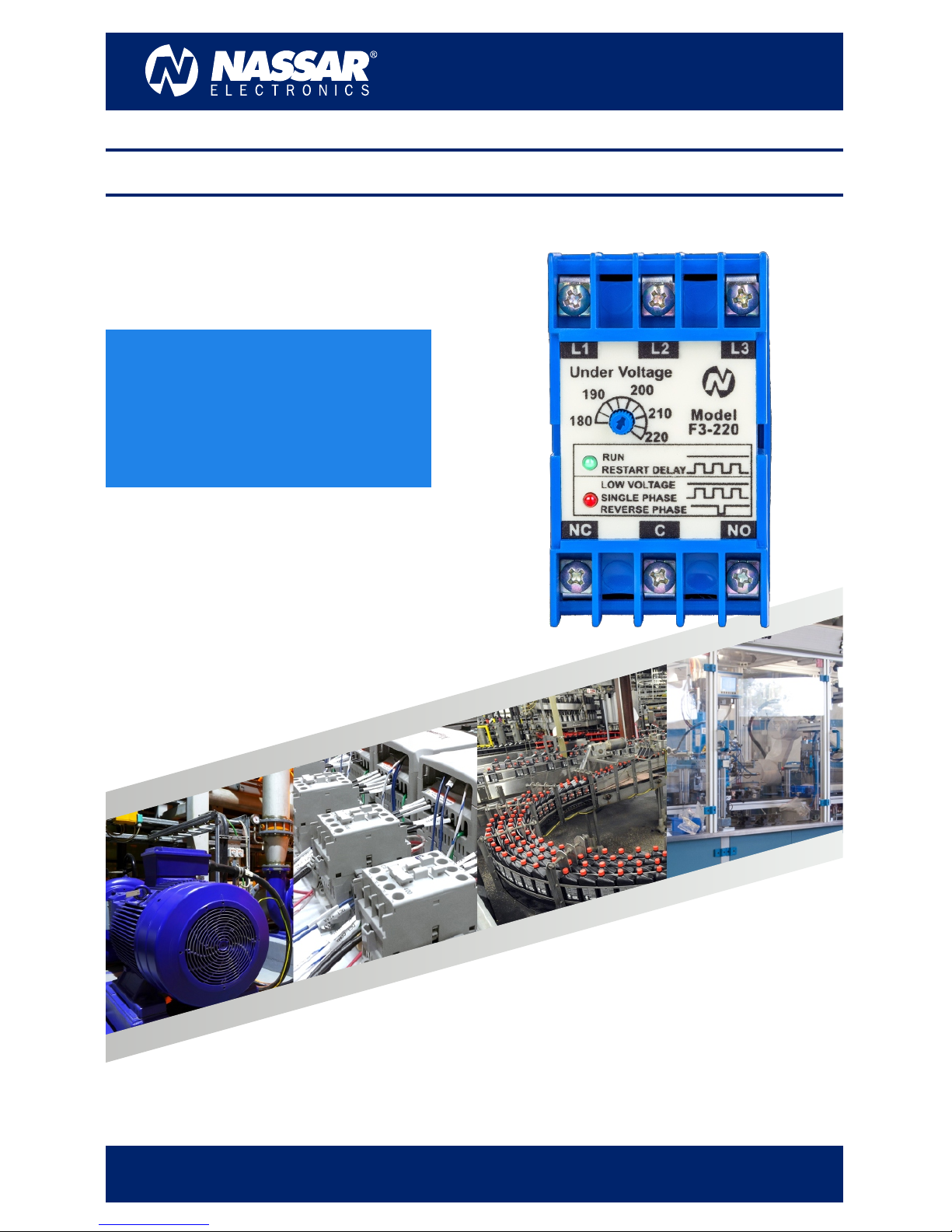
F3 FASEALERT-3 MANUAL
Description Features
Operation
The F3 series is a family of 3-phase voltage monitors. It
continuously measures the voltage of each of the
three phases with microcontroller accuracy and
compares the value with preset trip points. It
separately senses phase reversal and loss, as well as
under and unbalanced voltages.
Protection is assured during periods of large voltage
uctuations or when regenerated voltages are
present.
Trip and restart delays are included to prevent
nuisance tripping and short cycling of sensitive
equipment. The isolated 10A SPDT output relay
contact trips when a phase voltage exceeds the trip
limit after the time established by the trip delay.
The under voltage limit is adjustable.
Both delta and wye systems can be monitored; no
connection to neutral is needed.
The FASEALERT-3 protects motors against:
Under voltage, phase loss, voltage unbalance and
reverse phase sequence. To adjust the Under Voltage
limit set the knob at the desired level.
Note: If the “Reverse Phase” LED turns ON when you
are connecting the F3 for the rst time, swap the
cables connected to the L1 and L2 terminals and the
fault LED should turn OFF.
UPON APPLICATION OF LINE VOLTAGES
ŸThe output relay is de-energized
ŸThe failure red LED is OFF
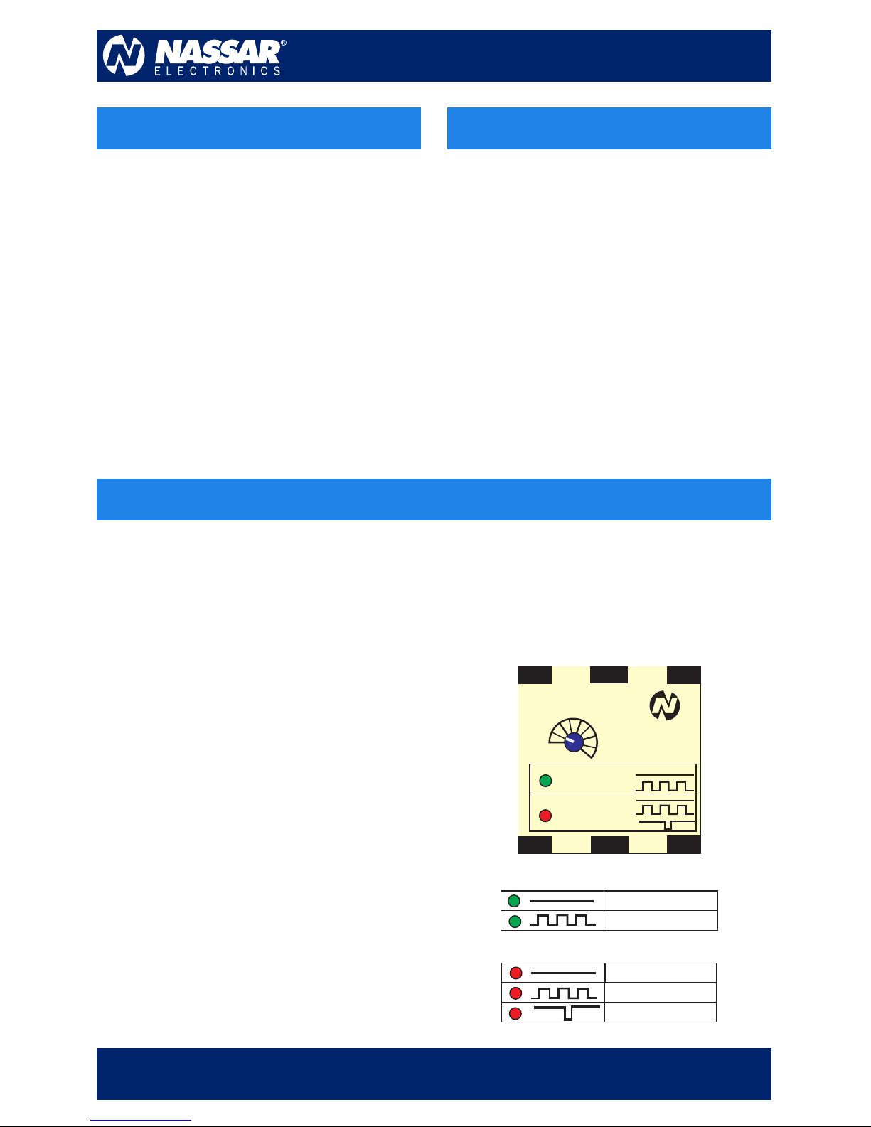
ŸThe “RUN” green LED ashes during the restart
delay (Depending on the model), and when it ends
the green LED stays ON and the output relay is
energized.
IN NORMAL VOLTAGES
ŸThe output relay is energized.
ŸThe “RUN” green LED is ON.
ŸThe red failure LED is OFF.
UPON A VOLTAGE FAILURE
ŸThe red LED indicates the corresponding failure
and the “RUN” green LED goes OFF.
ŸOnce the adjusted period in the trip delay has
passed, the output relay is de-energized to
disconnect the motor.
ŸProtects against phase reversal, phase
loss, under and unbalanced voltages.
ŸSurface mounting or 35mm DIN rail.
ŸIsolated, 10A, relay contacts.
ŸLEDs indicate each fault, status, and
time delays.
Ÿ3-wire connection for delta or wye
systems.
WHEN VOLTAGES GO BACK TO NORMAL
ŸThe red failure LED is OFF.
ŸThe output relay stays de-energized.
ŸThe “RUN” green LED ashes during the restart
delay (optional), and once it’s nished, the green
LED stays ON, then the output relay is energized
to reconnnect the motors.
Model
F3-220
Under Voltage
L2 L3
L1
NC CNO
210
220
180
200
190
SINGLE PHASE
LOW VOLTAGE
REVERSE PHASE
RUN
RESTART DELAY
RUN
RESTART DELAY
GREEN LED STATUS
SINGLE PHASE
LOW VOLTAGE
REVERSE PHASE
RED LED STATUS