Nassar PM-22 User manual

SINCE 1973
PUMP MONITOR
MODEL
PM-22
www.nassarelectronics.com
The best solutions for
automation and protection
User Manual
PM-22 PUMP MONITOR MANUAL ENGLISH 2018
viernes, 4 de octubre de 2019 10:45:06 a. m.

www.nassarelectronics.com 2
PM-22 PUMP MONITOR MANUAL
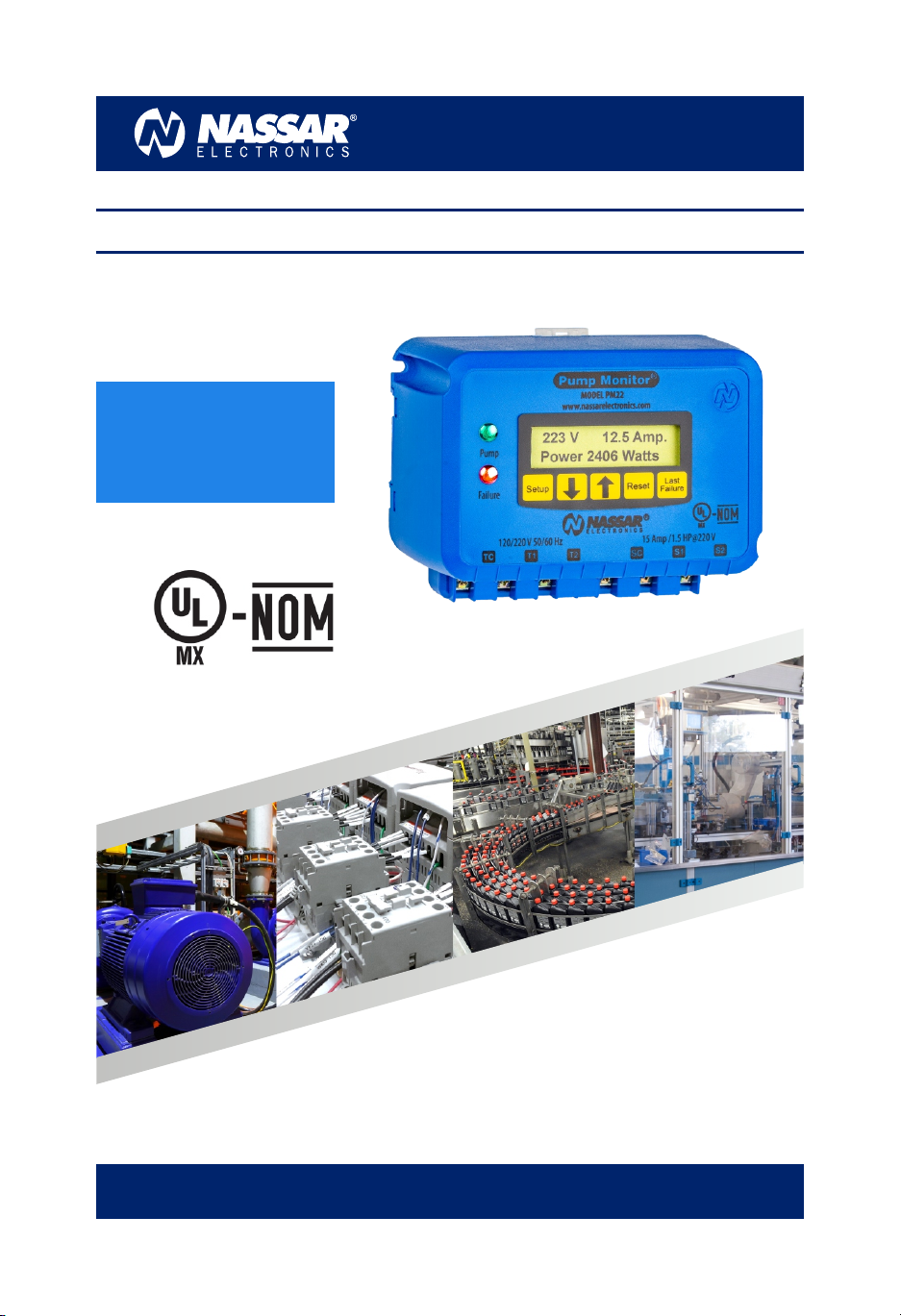
The PM-22 Series is a variety of pump monitors
designed to protect single-phase pumps from dry-
well, dead-head, jammed impeller, waterlogged tanks,
r a p i d c y c l i n g , u n d e r / o v e r v o l t a g e a n d
over/underload. It includes an LCD display that shows
the voltage, current, power consumption and faults.
The trip point is user-adjustable and it also features
automatic calibration allowing adjustments for
specic pumping applications, reducing the
possibility of false or nuisance tripping. A unique
microcontroller-based sensing circuit constantly
monitors the power and line voltage for uctuations.
When a fault is detected the PM-22 after the trip
delay— will turn off the pump . The user can select
automatic or manual reset, when automatic reset is
selected the PM -22 will turn on the pump after the
restart delay (delay is user -adjustable).
The PM-22 has an internal contactor capable of
starting motors up to 1.5 HP.
Description
Wiring
The PM-22 is used in single phase pumps with a
current consumption in the range of 4 to 15 Amps. This
unit should be mounted in a convenient location in or
near the pump control box. If the location is wet or
dusty a NEMA 3R, 4, or 12 enclosure should be used.
The PM-22 must be protected by a fuse or circuit
breaker to avoid any damage. The following diagrams
show how to connect the PM-22 depending on the
supply voltage available:
120VAC SUPPLY VOLTAGE
Features
ŸProtects pumps from dry-well, dead-
head, jammed impeller, waterlogged
tanks, rapid cycling, under /over
voltage, and over/underload.
ŸStarts motors up to 1.5 HP without the
need of an external contactor.
ŸStores faults on memory.
ŸLCD displays: Line voltages, current,
power, failures, time delays, and a
setup menu.
ŸAuto calibration.
ŸManual or automatic reset.
CB = CIRCUIT BREAKER OR FUSE
CA = CONTROL CONTACT
DANGER!
Potentially hazardous voltages are present. Electrical
shock can cause death or serious injury.
Installation should be done by qualified personnel
following all National, State & Local Codes.
BE SURE TO REMOVE ALL POWER SUPPLYING THIS
EQUIPMENT BEFORE CONNECTING OR DISCONNECTING
THE WIRING.
READ THE INSTRUCTIONS BEFORE INSTALLING OR
OPERATING THIS DEVICE.
KEEP THIS MANUAL FOR FUTURE REFERENCE.
The contact “CA” could be a pressure or float switch, a
manual switch or any other control used to start/stop
the pump automatically or manually.
120 VAC
PUMP
CB
CA
T1 S1
TC SC
T2 S2
PUMP-MONITOR
220 VAC SUPPLY VOLTAGE
220 VAC PUMP
CB
CA
T1 S1
TC SC
T2 S2
PUMP-MONITOR
CB = CIRCUIT BREAKER OR FUSE
CA = CONTROL CONTACT
PM-22 PUMP MONITOR MANUAL ENGLISH 2018
viernes, 4 de octubre de 2019 10:45:09 a. m.

www.nassarelectronics.com 3
PM-22 PUMP MONITOR MANUAL
Supply Voltage Selection
When the Pump-Monitor is turned ON for the first time
it will ask the user to input if the supply voltage is
220VAC or 120VAC. This selection is done to calibrate
the voltage readings.
Once the supply voltage is selected it won’t ask the
user again for this setup. If the supply voltage
configuration needs to be changed, power off the PM-
22 by removing the supply voltage. Then keep the
Reset button pressed while you turn ON the PM-22
again. If done correctly the PM-22 will ask for the
supply voltage again.
SELECT:
220 V PRESS RESET
Before the PM-22 unit is ready to be used it MUST BE
CALIBRATED. Calibration may be performed as many
times as desired.
Important Note: Please make sure the PM-22 is
calibrated during normal pumping conditions.
While the pump is operating press and hold both
arrow buttons until LCD displays the calibration.
Automatic calibration
UL=780 OL=1500
CAL. P=1200 W
Setup Reset Last
Failure
CALIBRATION
AUTO CALIBRATION
WAIT 5 SEC.
The PM-22 measures the power and sets the
calibration for underload (UL) at 65% of the power
consumption and at 125% for overload (OL). These are
the recommended values, but they can be manually
adjusted later if desired.
The calibration is permanently stored, it does not
need to be recalibrated if power is lost.
Verify that the pump is running normally (i.e. the
system is pumping water and the motor current is
normal). Try to achieve the maximum water flow rate.
Calibration on a fully recovered well is recommended.
The calibration may be repeated to assure that setup
was done when the pump was running under normal
conditions.
SET: RESET DELAY
60 Min.
SET RESET:
MANUAL
SET:UNDER LOAD
UL=2312 W
Setup
Press the SETUP button to select between manual or
automatic reset. Press the downwards arrow button to
choose MANUAL reset or the upwards arrow button to
choose AUTOMATIC reset.
RESET DELAY
Press the SETUP button again. If the AUTOMATIC
option is selected the reset delay setup will be shown.
Press the up or down arrow buttons to adjust the
desired reset delay from 1 to 120 minutes.
UNDERLOAD
Proceed by pressing again the SETUP button, the
underload trip value will be displayed. This setup
allows to modify the underload protection if the
au t om ati c ca li b ra t io n ad j us tm e nt w a s n o t
appropriate. The PM-22 will disconnect the pump if
the power is below the selected value.
Use the arrow buttons to set up the desired value in
10W increments. If the button is kept pressed it will
move by 100W increments.
OVERLOAD
When pressing the SETUP button the overload setup is
displayed. This setup allows to modify the overload
protection if the automatic calibration adjustment
was not appropriate. The PM-22 will disconnect the
pump if the power is above the selected value.
SET:OVER LOAD
OL=3451 W
PM-22 PUMP MONITOR MANUAL ENGLISH 2018
viernes, 4 de octubre de 2019 10:45:09 a. m.

www.nassarelectronics.com 4
PM-22 PUMP MONITOR MANUAL
Use the arrow buttons to set up the desired value in
10W increments. If the button is kept pressed it will
move by 100W increments. The overload value should
not be less than the underload value. If this happens
an error will be displayed until the overload setting is
increased.
UNDER VOLTAGE
Press the SETUP button and the low voltage setup will
be displayed , if the voltage is under this value the
pump will shut down.
SET: UNDER
VOLTAGE= 200 V
Operation
NORMAL CONDITIONS:
The Pump LED is ON when the pump start, and the
Failure LED is OFF, the display shows the voltage,
current and power consumption.
234 V 12.5 Amp.
Power 2645 W
FAULTS:
If a failure occurs the Failure LED turns ON and the LCD
diplays the fault during trip delay. After the trip delay
the pump will shut down.
Fault Examples
FAILURE
UNDER VOLTAGE
POWER 1456 W
UNDER LOAD
POWER 3456 W
OVER LOAD
FAILURE
RAPID CYCLING
If the pump presents an overload or underload
condition, the power consumption will be displayed
on the screen. This is useful when the system presents
considerable load variation and the automatic
calibration values need to be adjusted.
AUTOMATIC RESET:
After a failure has occured (except under/over
voltage), the PM-22 will start to count down the time
set on the restart delay (if the automatic reset is
enabled). The pump will restart when the timer
finishes.
RESET DELAY
6 MIN. LEFT
The display shows the time left to restart the motor. If
it’s required to restart without waiting, press the
“Reset” button to start the motor immediately.
MANUAL RESET:
If the PM-22 is set to manual reset it will not restart the
motor until the RESET button is pressed and the fault
condition is no longer present.
MANUAL RESET
PRESS RESET
FAILURE MEMORY:
Failures are stored in the internal memory. When a
failure is detected a letter “F” will appear in the first line
on the right upper side of the display indicating a
failure has occured.
234 V 12.5 Amp. F
Power 2645 W
SET:OVER
VOLTAGE= 245 V
Use the arrow buttons to adjust the desired voltage.
Press SETUP again to exit.
OVERVOLTAGE
Finally, press the SETUP button and the over voltage
setup will be displayed , if the voltage is over this value
the pump will shut down.
PM-22 PUMP MONITOR MANUAL ENGLISH 2018
viernes, 4 de octubre de 2019 10:45:09 a. m.

www.nassarelectronics.com 5
PM-22 PUMP MONITOR MANUAL
To check what failure occured, press the LAST FAILURE
button. The last failure will be shown for 3 s and then it
will be erased automatically.
LAST FAILURE
RAPID CYCLING
UNDERLOAD PROTECTION
The PM-22 protects the motor when a loss of suction is
detected. When this happens, the motor uses less
power and the PM-22 shuts down the motor after a 5 s
trip delay.
The underload setup is set at 65 % of the power
consumption during automatic calibration, but it can
also be adjusted manually.
In the unusual event that the system has a wide power
variation and it’s consumption goes below 65% there
will be a false triggering of the underload protection.
In this case underload should be adjusted manually to
a lower value in the setup menu .
OVERLOAD PROTECTION
The PM-22 protects the motor when an overload is
detected, when this happens the motor uses more
power and the PM-22 shuts down the motor after a trip
delay as shown in the graphic below.
100 125 150 175 200 225 250 275
5
10
15
20
25
OVERLOAD %
TRIP DELAY Sec.
OVER LOAD TRIP DELAY
The overload trip point is set to 125% of the power
consumption during automatic calibration, but it can
also be adjusted manually.
UNDER VOLTAGE PROTECTION
The PM-22 protects the motor if the voltage drops
from normal conditions. It shuts down the motor after
a 5 s trip delay. The under voltage protection is user-
adjustable.
To reset from this fault, the voltage has to increase 2%
above the under voltage value.
OVER VOLTAGE PROTECTION
The PM-22 protects the motor if the voltage is over
from normal conditions. It shuts down the motor after
a 5 s trip delay. The over voltage protection is user-
adjustable.
To reset from this fault, the voltage has to decrease 2%
above the over voltage value.
RAPID CYCLING PROTECTION
Pumps heat up if they are started very frequently. Such
heating could damage the pump even if an overload is
not present.
When the PM-22 detects that the pump starts more
than 4 times per minute, it will shutdown the pump to
prevent any damage.
PM-22 PUMP MONITOR MANUAL ENGLISH 2018
viernes, 4 de octubre de 2019 10:45:10 a. m.

www.nassarelectronics.com 6
Panel mounting
Panel mounting for this equipment is available using the adapter plate model PMF-237 (sold separately).
Mounting on a panel door allows to visualize the LED indicators , it also makes setup adjustments easier. If this unit
is panel mounted, the panel needs to be installed indoors.
Din rail mounting
Mounting hole
Mounting hole
Mounting options & Dimensions
This unit can be mounted on a standard 35 mm DIN rail or screwed into a surface using the screws included in the
package.
Enclousure Dimensions: 5.7 x 4.1 x 2.4 in
PM-22 PUMP MONITOR MANUAL
PM-22 PUMP MONITOR MANUAL ENGLISH 2018
viernes, 4 de octubre de 2019 10:45:10 a. m.

PM-22 PUMP MONITOR MANUAL
Specifications
SUPPLY VOLTAGE
OVER VOLTAGE RANGE
UNDER VOLTAGE RANGE
OUTPUT CONTACT RATING
CONTACT LIFE
TRIP DELAY UNDER LOAD/VOLTAGE
RESTART DELAY
RAPID CYCLING
OPERATON TEMPERATURE
STORAGE TEMPERATURE
INPUT POWER
WEIGHT
15 Amps @ 220 VAC, 1.5 HP @ 220 VAC, 1 HP @ 120 VAC
100,000 operations
5 seconds.
1 to 120 minutes or manual reset.
4 start/stop cycles in 60 seconds
5 to + 149 °F (-15 to + 65 °C)
-4 to + 158 °F (-20 to + 70 °C)
4 W Approx.
17.6 oz
*Specifications subject to change without notice.
WARRANTY
These products are warranted to be free from defects in workmanship or material under normal service and use for a period of
three (3) years from date of manufacture. Nassar Electronics shall, at its option, repair or replace F.O.B. point of manufacture the
portion of the product found by Nassar Electronics to be defective. All replacements or repairs necessitated by inadequate
maintenance, normal wear and usage, unsuitable power sources or environmental conditions, accident, misuse, improper
installation, modification, repair, use of unauthorized replacement parts, storage or handling, or any other cause not the fault of
Nassar Electronics are not covered by this limited warranty, and shall be at the buyer’s expense. All costs of dismantling,
reinstallation and freight, and the time and expenses shall be borne by the buyer.
LIMITATION OF REMEDY AND LIABILITY
NASSAR ELECTRONICS SHALL NOT BE LIABLE FOR DAMAGES CAUSED BY DELAY IN PERFORMANCE. THE REMEDIES OF THE BUYER
SET FORTH IN THIS AGREEMENT ARE EXCLUSIVE. IN NO EVENT, REGARDLESS OF THE FORM OF THE CLAIM OR CAUSE OF ACTION
(WHETHER BASED IN CONTRACT, INFRINGEMENT, NEGLIGENCE, STRICT LIABILITY, OTHER TORT OR OTHERWISE), SHALL NASSAR
ELECTRONIC’S LIABILITY TO THE BUYER AND/OR ITS CUSTOMERS EXCEED THE PRICE TO THE BUYER OF THE SPECIFIC GOODS
MANUFACTURED OR SERVICES PROVIDED BY NASSAR ELECTRONICS GIVING RISE TO THE CLAIM OR CAUSE OF ACTION. THE BUYER
AGREES THAT IN NO EVENT SHALL NASSAR ELECTRONIC’S LIABILITY TO THE BUYER AND/OR ITS CUSTOMERS EXTEND TO INCLUDE
INCIDENTAL, CONSEQUENTIAL OR PUNITIVE DAMAGES. THE TERM “CONSEQUENTIAL DAMAGES” SHALL INCLUDE, BUT NOT BE
LIMITED TO, LOSS OF ANTICIPATED PROFITS, REVENUE OR USE AND COSTS INCURRED INCLUDING WITHOUT LIMITATION FOR
CAPITAL, FUEL AND POWER, AND CLAIMS OF THE BUYER’S CUSTOMERS.
120/220 VAC ± 15 %, 50/60 Hz
120-140/ 220-260 VAC
90-120/190 - 220 VAC
Nassar Electronics
J. M. Salas 124 Pte.
64290 Monterrey, N. L. México
email: [email protected]
Ph.+ 52 (81)-8351-0006
UL MX certied to NOM
PM-22 PUMP MONITOR MANUAL ENGLISH 2018
viernes, 4 de octubre de 2019 10:45:10 a. m.
Table of contents
Other Nassar Monitor manuals