Nat 802-009 Owner's manual

Northern Airborne Technology Ltd.
1925 Kirschner Road
Kelowna, BC, Canada.
V1Y 4N7
Telephone (250) 763-2232
Facsimile (250) 762-3374
Issued on the authority of Northern Airborne Technology Ltd.
Copyright 2005
Installation and Operation Manual
802-009 Switch Panel
SM802
ISSUE 4.12

802-009 Switch Panel
SM802 Installation and Operation Manual
Installation and Operation Manual Page ii
ENG-FORM: 820-0115.DOT
CONFIDENTIAL AND PROPRIETARY TO NORTHERN AIRBORNE TECHNOLOGY LTD.

802-009 Switch Panel
SM802 Installation and Operation Manual
Installation and Operation Manual Page iii
ENG-FORM: 820-0115.DOT
CONFIDENTIAL AND PROPRIETARY TO NORTHERN AIRBORNE TECHNOLOGY LTD.
Prepared By: Checked By: Certification: Approved By:
The status of this installation and operation manual is controlled by issue shown on the title page. The
status of each section is controlled by revision shown in the footer of each page. All revisions affecting
sections of this manual have been incorporated into the latest issue.
ISSUE/REVISION RECORD
Manual Issue
Number Section
Revision Number Revision Description Issue Date
4.12 Section 2 Rev. 1.00 Update for current drawings. Jun 24, 2010
4.11 Section 1 Rev. 1.00
Section 2 Rev. 1.00
Section 3 Rev. 1.00
Update to current templates. Sep 12, 2008

802-009 Switch Panel
SM802 Installation and Operation Manual
Installation and Operation Manual Page iv
ENG-FORM: 820-0115.DOT
CONFIDENTIAL AND PROPRIETARY TO NORTHERN AIRBORNE TECHNOLOGY LTD.
Table of Contents
Section Title Page
1. Description
1.1 Introduction 1-1
1.2 Product Description 1-1
1.3 Design Features 1-1
1.4 Specifications 1-2
1.4.1 Electrical Specifications 1-2
1.4.2 Physical Specifications 1-2
1.4.3 Environmental Specifications 1-3
1.4.4 Product Approval 1-3
2. Installation
2.1 Introduction 2-1
2.2 Unpacking and Inspection 2-1
2.2.1 Warranty 2-1
2.3 Continued Airworthiness 2-1
2.4 Installation Procedures 2-1
2.4.1 Warnings 2-1
2.4.2 Cautions 2-2
2.4.3 Cabling and Wiring 2-2
2.4.4 Mechanical Mounting 2-3
2.4.5 Installation Notes 2-3
2.4.6 Post-Installation Checks 2-5
2.5 Adjustments and Connections 2-5
2.5.1 Adjustments 2-5
2.5.2 Electrical Connections 2-6
2.5.3 Numerical Pin Identification List 2-6
2.6 Installation Drawings 2-7
3. Operation
3.1 Introduction 3-1
3.2 General Information 3-1
3.3 Controls and Indicators 3-2
3.3.1 Master Volume, Transceiver and Receiver Controls 3-2
3.3.2 MIC SELECT Switch 3-3
3.3.3 BOTH/VOICE/IDENT Switch 3-3
3.3.4 NORM MIC/OXY MIC Switch 3-3
3.3.5 HI/LO MKR Sensitivity Switch 3-3
3.3.6 Transmission Functions 3-3

802-009 Switch Panel
SM802 Installation and Operation Manual
Section 1 Rev: 1.00 Issue 4 Page 1-1
ENG-FORM: 800-0114.DOT
CONFIDENTIAL AND PROPRIETARY TO NORTHERN AIRBORNE TECHNOLOGY LTD.
Section 1 Description
1.1 Introduction
Information in this section consists of product description, design features and specifications for the
802-009 Switch Panel. All derivative product information shall be contained in the applicable manual
supplement, which may be obtained from NAT as required.
Review all notes, warnings and cautions.
1.2 Product Description
The 802-009 Switch Panel is designed to control a single Model 700-xxx Digital Audio Control Amplifier. It
also provides microphone audio switching and keying operations for four radio transmitters in addition to
features such as antenna switching unit control, marker (MKR) receiver sensitivity control and public
address (PA) amplifier control. The 802-009 Switch Panel continuously reads the status of its own audio
control switches and volume control potentiometers and compiles this information into the form of a digital
signal. The digital signal is sent to the Model 700 from the switch panel in RS422 serial format via a
twisted, shielded wire pair. The Model 700 receives, demultiplexes and converts this digital signal into
audio control information.
1.3 Design Features
The 802-009 Switch Panel is capable of digitally controlling all Model 700 amplifier functions. These
include the 12 receiver input switches and individual volume controls, the four sidetone input switches
and sidetone volume control, three microphone inputs, the microphone input switch, antenna switching,
the interphone switches and volume control, the cockpit speaker switch and volume control, the
headphone volume control and the NAV/ADF Voice/Ident filter switching functions.
The 802 Switch Panel is a customizable unit capable of providing control for up to four transceivers, eight
receivers and a public address. For information on other configurations, contact the Product Support
Department at NAT Ltd.
Panel nomenclature and knob illumination is provided on the 802-009 Switch Panel. The power supply
inputs for the panel overlay and knob internal light plate are independent of each other and may be lit at
different levels of brightness. The MIC SELECT knob and the NORM MIC/OXY MIC knob are lit with the
panel overlay. Neoprene washers are installed around each of the volume control knobs between the
overlay and front panel sheet metal to prevent light leakage from being radiated by the knob illuminating
light plate into the cockpit. The PHONE and PASS knobs are always in the OUT and lighted position,
since there is no switching associated with them.

802-009 Switch Panel
SM802 Installation and Operation Manual
Section 1 Rev: 1.00 Issue 4 Page 1-2
ENG-FORM: 800-0114.DOT
CONFIDENTIAL AND PROPRIETARY TO NORTHERN AIRBORNE TECHNOLOGY LTD.
1.4 Specifications
1.4.1 Electrical Specifications
Power
Input +28 Vdc at 0.30 A max.
1 A circuit breaker recommended.
Lighting 0 to 115 Vac, 400 Hz.
Independent from knob lighting.
Knobs 0 to 5 Vdc.
Independent from faceplate lighting.
Knobs light in OUT or ON position only.
Mic Inputs
NORM MIC 35 ±5 mA microphone bias current.
OXY MIC 35 ±5 mA microphone bias current.
Outputs
HOT MIC A direct connection from the selected mic input to the HOT MIC
output, which is connected to the Model 700 amplifier HOT MIC
input.
Transmitter & PA MIC’s A direct connection from the selected mic input to the selected
transmitter or PA mic output.
MUX Data RS422
Volume Controls
PASS Impedance 10 kΩ
Power 0.5 W
BRIEFER Impedance 10 kΩ
Power 0.5 W
1.4.2 Physical Specifications
Height 3.93" (99.8 mm) max.
Depth 6.03" (153.2 mm) max. behind panel, excluding connector
Width 5.67" (144.0 mm) max.
Weight 3.0 lbs (1.4 kg) max.
Mounting Panel mount with four 8-32 screws

802-009 Switch Panel
SM802 Installation and Operation Manual
Section 1 Rev: 1.00 Issue 4 Page 1-3
ENG-FORM: 800-0114.DOT
CONFIDENTIAL AND PROPRIETARY TO NORTHERN AIRBORNE TECHNOLOGY LTD.
Connector 55 pin circular
Faceplate Grey with white text
1.4.3 Environmental Specifications
Temperature -55 to +70°C
Altitude 70,000 feet
Qualification of the 802-009 Switch Panel was completed in accordance with
DO-160C Env. Cat. [A2F2]-BA[CL]XXXXXXZ[BZ]AZZUZLXX.
Note: Refer to Environmental Qualification Form located in Section 2 of this Manual for complete details
of the environmental categories.
1.4.4 Product Approval
FAA: TSO-C50c (RTCA/DO-170, RTCA/DO-160C, RTCA/DO-178A Level 2)
Section 1 ends

802-009 Switch Panel
SM802 Installation and Operation Manual
Section 2 Rev: 1.01 Issue 4 Page 2-1
ENG-FORM: 805-0121.DOT
CONFIDENTIAL AND PROPRIETARY TO NORTHERN AIRBORNE TECHNOLOGY LTD.
Section 2 Installation
2.1 Introduction
Information in this section consists of unpacking and inspection procedures, installation procedures,
post-installation checks and installation drawings for the 802-009 Switch Panel.
Review all notes, warnings and cautions.
2.2 Unpacking and Inspection
Unpack the equipment carefully and locate the warranty card. Inspect the unit visually for damage due to
shipping and report all such claims immediately to the carrier involved. Check that all items listed below
are present before proceeding and report any shortage immediately to your supplier:
- Warranty Card
- Operators Manual
- Certificate of Conformity or Release Certification
2.2.1 Warranty
All Northern Airborne Technology Ltd. products are warranted for 2 years from date of installation by an
authorized Northern Airborne Technology Ltd. dealer, to be free of defects in workmanship or
performance. This warranty covers all materials and labour, but is exclusive of any transport to deliver the
defective unit to and from Northern Airborne Technology Ltd. or its designated warranty repair center, or
any labour to remove or re-install the defective unit in the aircraft. Contact Northern Airborne Technology
Ltd. for any questions regarding this warranty, its applicability to your units and/or for return authorization.
Northern Airborne Technology Ltd. is the final arbitrator concerning warranty administration. Units which
have been physically damaged, burned, immersed in water or otherwise abused beyond the scope of
normal use will not be considered for warranty. WARRANTY IS VOID UNLESS THE PRODUCT IS
INSTALLED BY AN AUTHORIZED NORTHERN AIRBORNE TECHNOLOGY LTD. DEALER. Product
for which a warranty card is not returned shall be warranted from date of manufacture.
2.3 Continued Airworthiness
Maintenance of the 802-009 Switch Panel is ‘on condition’ only. Periodic maintenance of this product is
not required.
2.4 Installation Procedures
2.4.1 Warnings
WARNING:
High volume settings can cause hearing damage.
Set the headset volume control to the minimum volume setting prior to
conducting tests, and slowly increase the headset volume to a
comfortable listening level.

802-009 Switch Panel
SM802 Installation and Operation Manual
Section 2 Rev: 1.01 Issue 4 Page 2-2
ENG-FORM: 805-0121.DOT
CONFIDENTIAL AND PROPRIETARY TO NORTHERN AIRBORNE TECHNOLOGY LTD.
2.4.2 Cautions
CAUTION:
Do not bundle any lines from this unit with transmitter coax lines. Do not bundle any audio or DC
power lines from this unit with 400 Hz synchro wiring or AC power lines. Do not position this unit or
wiring from this unit next to any device with a strong alternating magnetic field such as an inverter,
or significant audio interference will result.
CAUTION:
In all installations, use shielded cable exactly as shown and ground as indicated. Significant ground loop
and noise problems may result from not following these guidelines. Ensure that the chassis is grounded
to provide proper shield terminations.
Ensure the microphone and headphone jacks are isolated from the airframe ground. Use caution
when routing microphone wiring, as it carries low-level signals prone to coupling from other sources.
Do not take a ground from the instrument panel or similar location that shares a ground return with a
turn and bank, horizon or other motor driven instrument. This may cause the unit to pick up the
sound of the motor as ground loop interference.
2.4.3 Cabling and Wiring
All wire shall be selected in accordance with the original aircraft manufacturer's Maintenance Instructions
or AC43.13-1B Change 1, Paragraphs 11-76 through 11-78. Unshielded wire types shall qualify to
MIL-W-22759 as specified in AC43.13-1B Change 1, Paragraphs 11-85, 11-86, and listed in Table 11-11.
For shielded wire applications, use Tefzel MIL-C-27500 shielded wire with solder sleeves (for shield
terminations) to make the most compact and easily terminated interconnect. Follow the wiring diagrams in
Section 2.6 as required.
Allow 3" from the end of the shielded wiring to the shield termination. Reference the interconnect drawing
in Section 2.6 for shield termination details. Aircraft harnessing shall permit the unit to be lowered from
the panel for easy access to all side adjustments. Do NOT mount the unit until all adjustments have been
performed.
Maintain wire segregation and route wiring in accordance with the original aircraft manufacturers
Maintenance Instructions. Coaxial cables shall be routed separately from existing wire bundles in the
aircraft to minimize electromagnetic coupling effects.
Unless otherwise noted, all wiring shall be a minimum of 24 AWG, except power and ground lines, which
shall be a minimum of 20 AWG. Reference the Interconnect drawing for additional specifications. Check
that the ground connection is clean and well secured, and that it shares no path with any electrically noisy
aircraft accessories such as blowers, turn and bank instruments or similar loads. Power to this unit must
be supplied from a separate circuit breaker or fuse (fast blow), and not attached to any other circuit
breaker without additional protection. Verify that the selected circuit breaker size and wire gauge are
adequate for the installation using the techniques specified in AC43.13-1B Change 1, Paragraphs 11-47
through 11-51 and 11-66 through 11-69.

802-009 Switch Panel
SM802 Installation and Operation Manual
Section 2 Rev: 1.01 Issue 4 Page 2-3
ENG-FORM: 805-0121.DOT
CONFIDENTIAL AND PROPRIETARY TO NORTHERN AIRBORNE TECHNOLOGY LTD.
2.4.4 Mechanical Mounting
Installation dimensions are shown on the Outline drawing 802-009 listed in Section 2.6. No shock or
vibration isolators are required for mounting.
The 802-009 Switch Panel may be mounted to a metal, plastic or composite surface however, it is
absolutely necessary to ground the enclosure to the metal aircraft ground structure. When mounting to a
plastic or composite surface, use a grounding strap. An 8-32" x 1/2" grounding stud is provided on the
rear of the enclosure for chassis grounding. The switch panel enclosure and mounting surface is finished
with an electrically conductive film. It is not necessary to remove the film for electrical bonding to any
metal aircraft ground structure.
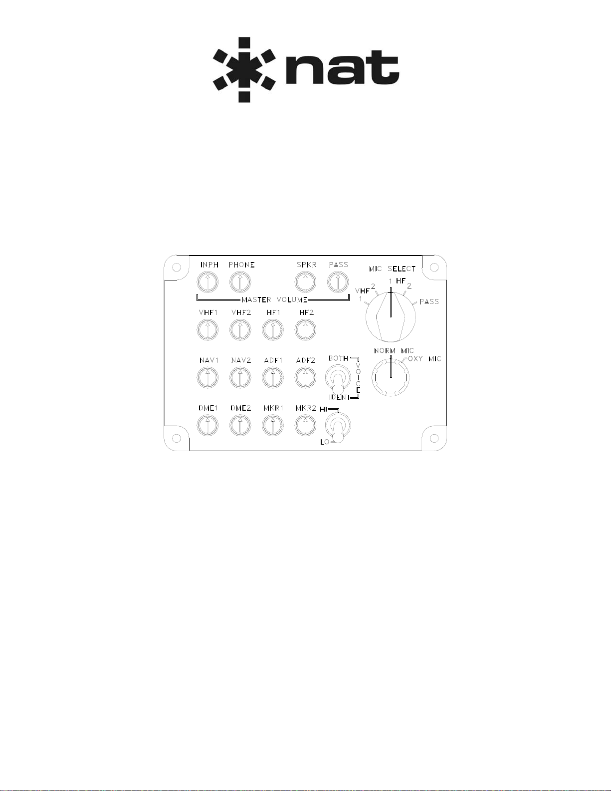
If replacement of the front panel overlay is necessary, it may be removed by first loosening the set screws
on the MIC SELECT and NORM MIC/OXY MIC knobs and removing the knobs. Then the four 4-40 flush
socket head screws on the backside of the mounting flanges may be removed and the overlay may be
pulled off straight forward. Installing a new overlay requires the same steps in reverse order however,
care should be taken to align the overlay before tightening the four 4-40 socket head screws so that the
lighting power connector mates properly and the lighted knobs do not rub on their through holes in the
overlay.
2.4.5 Installation Notes
Connecting P1-8 of the pilot's 802-009 to P1-7 of the copilot's 802-009 provides relay switching of the
802-009 PASS volume control to the paging amplifier. When the PA volume relay internal to the 802-009
is in the relaxed position, the BRIEFER preset volume potentiometer in the rear of the copilot 802-009 is
connected to the paging amplifier. When the TRANSMIT SELECTOR switch is placed in the PASS
position and PTT is keyed, the PA VOLUME relay is energized, connecting the PASS volume control on
the 802-009 front panel to the paging amplifier. The PA volume interconnect line allows this logic to
function for both pilot and copilot positions.
If the INPH LISTEN input on the 802-009 is grounded, then interphone audio may be heard on the
headphones at all times however, the INPH switch must still be turned ON in order to talk on the
interphone with the normal boom or oxygen mask mics. In addition to the HOT MIC microphone output,
there are six other microphone outputs provided, one each for the selected transmitter or PA amplifier.
2.4.5.1 MIC INPUTS
NORM MIC The NORM MIC input, intended for the normal boom or headset microphone, is
compatible with carbon and amplified dynamic microphones. This input may be used for
both interphone communications and transmitting. A transmitter is keyed for this mic input
using the yoke mounted PTT switch.
OXY MIC The OXY MIC input, intended for the oxygen mask microphone, is compatible with
carbon and amplified dynamic microphones. This input may be used for both interphone
communications and transmitting. A transmitter is keyed for this mic input using the yoke
mounted PTT switch.

802-009 Switch Panel
SM802 Installation and Operation Manual
Section 2 Rev: 1.01 Issue 4 Page 2-4
ENG-FORM: 805-0121.DOT
CONFIDENTIAL AND PROPRIETARY TO NORTHERN AIRBORNE TECHNOLOGY LTD.
HAND MIC The HAND MIC input, intended for the hand held microphone, is compatible with carbon
and amplified dynamic microphones. It receives its bias current from the Model 700
amplifier through the 802-009 to Model 700 HOT MIC connection. This input may be
used for transmitting only and not for interphone communications. A transmitter is keyed
for this mic input using the PTT switch on the hand held microphone.
2.4.5.2 OUTPUTS
HOT MIC A HOT MIC microphone output is provided on the 802-009 to make this connection to the
Model 700 HOT MIC input. This connects any one selected microphone input (NORM,
OXY, or HAND) directly to the Model 700 HOT MIC input, which channels the
microphone audio to the Model 700 cockpit voice recorder (CVR) output for hot
microphone recording purposes. The HOT MIC input of the Model 700 Amplifier is also
used for interphone communication with the NORM and OXY MIC inputs when the INPH
switch on the 802-009 is turned ON. The HAND MIC input is used for transmitting or PA
only and not for interphone communications.
TX & PA MICs During a transmit PTT, these outputs are simply a direct connection from the microphone
input being used to the selected transmitter or PA mic output. The mic audio input is
connected to the output selected by the MIC SELECT switch on the switch panel. These
outputs are intended for connection to respective transmitter and PA amplifier mic inputs.
MUX DATA This output is a RS422 differential data transmission line driver intended for connection to
the Model 700 amplifier MUX DATA input. It transfers all of the digital data necessary to
control Model 700 functions via a shielded twisted-pair wire cable up to 4,000 feet long.
2.4.5.3 VOLUME CONTROLS
RECEIVERS These volume controls are linear taper potentiometers connected internally to the digital
multiplexing circuitry. Volume control range and curve are defined in Model 700 amplifier
software.
INPH Same as RECEIVERS volume.
PHONE Same as RECEIVERS volume.
SPKR Same as RECEIVERS volume.
PASS/ The PASS volume knob controls the level of the PA amplifier output only when the MIC
BRIEFER SELECT Switch is in the PASS position. This is a 10 kΩ, 0.5 W, linear taper
potentiometer connected through relay switching logic to pin P1-14 of the Model 802.
Maximum volume position (fully clockwise) provides maximum resistance. Volume control
range and curve are determined by PA amplifier circuitry. Refer to Section 2.4.5 for more
details.
2.4.5.4 ANTENNA SWITCHING
P1-32 should be connected to 28 VDC or ground to suit the requirements of the Antenna Switching Unit.
When the MIC SELECT switch is in the HF1 position, P1-32 and P1-6 are connected internally. When the
MIC SELECT switch is in the HF2 position, P1-32 and P1-16 are connected internally.

802-009 Switch Panel
SM802 Installation and Operation Manual
Section 2 Rev: 1.01 Issue 4 Page 2-5
ENG-FORM: 805-0121.DOT
CONFIDENTIAL AND PROPRIETARY TO NORTHERN AIRBORNE TECHNOLOGY LTD.
2.4.6 Post-Installation Checks
2.4.6.1 Voltage/Resistance Checks
Do not attach the 802-009 until the following conditions are met.
Check the following:
a) Check P1, pin 55 for +28 Vdc relative to ground.
b) Check P1 pin 54 for continuity to power ground (less than 0.5Ω).
c) Check P1 pin 52 and P1 pin 53 for 115 Vac 400 Hz.
d) Check P1 pin 51 for continuity to chassis ground (less than 0.5Ω).
e) Check P1 pin 18 for continuity to ground when the PTT key switch is activated (less than
0.5Ω).
f) Check all shielded cable grounds for continuity to ground (less than 0.5Ω).
g) Check all speaker and mic inputs and outputs for correct HI/LO orientation.
2.4.6.2 Power On Checks
Power up the aircraft’s systems and confirm normal operation of all functions of the 802-009. Refer to
Section 3 (Operation) for specific operational details.
a) Begin with only the Pilot's headset installed, no hand mic. Confirm correct radio operation,
both receive and transmit and Interphone operation. Check yoke (or cyclic) switch action.
b) Plug in the Copilot's headset. Check for correct radio and Interphone operation. Check pilot's
transmit priority. Check yoke (or cyclic) switch functions.
c) Check Interphone operation between Pilot and Copilot positions.
d) Plug in the hand mic, if installed, and test for correct operation in all modes.
e) Plug in any remaining headsets, and check for correct Interphone operation.
Note: Incorrect jack wiring is a common fault for rear passenger stations, and may cause a wide
range of problems.
f) To verify proper operation, all functions and levels shall be checked in-flight.
g) Check preset adjustments are completed before aircraft departure.
Upon satisfactory completion of all performance checks, make all required log book entries, electrical
load, weight and balance amendments and other documentation as required by your local regulatory
agency before releasing the aircraft for service.
2.5 Adjustments and Connections
2.5.1 Adjustments
There are three screwdriver potentiometer adjustments on the 802-009 accessible through access holes
in the rear of the unit. These are for OXY MODE INPH VOL, BRIEFER VOL, and SDTN VOL.

802-009 Switch Panel
SM802 Installation and Operation Manual
Section 2 Rev: 1.01 Issue 4 Page 2-6
ENG-FORM: 805-0121.DOT
CONFIDENTIAL AND PROPRIETARY TO NORTHERN AIRBORNE TECHNOLOGY LTD.
The OXY MODE INPH VOL is used to adjust the preset interphone volume when the NORM MIC/OXY
MIC selector switch is in the OXY MIC position and the oxygen mask microphone is in use.
The SDTN VOL is used to adjust the volume of all sidetone inputs together, including PA sidetone.
For BRIEFER VOL description see PASS/BRIEFER in Section 2.4.5.3.
When the potentiometer is rotated fully clockwise, the selected volume will be at maximum and when it is
fully counterclockwise, it will be at its minimum.
2.5.2 Electrical Connections
Connections to the 802-009 are made through a single 55 pin MIL-C-26500 cylindrical bayonet coupling
type connector. The mating connector to be installed on the aircraft wire harness comes with a coupling
nut. A cable support is recommended for strain relief of wires exiting the mating connector.
Description Military Part Number
Cylindrical bayonet coupling type connector MS24264R22B55PN
Mating connector (with coupling nut) MS24266R22B55SN
Cable support MS27291-6
Numerical pin identification is shown in section 2.5.3.
2.5.3 Numerical Pin Identification List
The following table identifies the pins for 55-pin connector P1.
Pin Name Pin Name Pin Name
1 No connection (n/c) 20 TEST MODE JUMPER 39 HF-2 MIC
2 N/C 21 TEST MODE JUMPER 40 PAMIC
3 HOT MIC LO 22 N/C 41 HF-1 MIC
4 N/C 23 HAND MIC HI 42 VHF-2 MIC
5 N/C 24 NORM MIC HI 43 VHF-1 MIC
6 HF-1 ANTENNA SWITCHING 25 OXY MIC HI 44 XCVR-5 KEY
7 PA/Briefer Interconnect 26 OXY MIC LO 45 HF-2 KEY
8 PA/Briefer Interconnect 27 HF-1 KEY 46 PAKEY
9 HOT MIC HI 28 VHF-2 KEY 47 VHF-1 KEY
10 HAND MIC LO 29 N/C 48 MUX DATA HI
11 NORM MIC LO 30 N/C 49 MUX DATA LO
12 MIC AUDIO COMMON 31 MKR HI control 50 NORM discrete output
13 N/C 32 HF-1 & 2 ANTENNA
SWITCHING 51 Chassis ground
14 PA VOLUME 33 N/C 52 115 VAC, 400 Hz Hot
15 OXY MIC MODE
INTERCONNECT 34 N/C 53 115 VAC, 400 Hz
common
16 HF-2 ANTENNA SWITCHING 35 Ground 54 Power ground
17 INPH LISTEN (to GND) 36 GND FROM NORM/OXY MIC
TIPS 55 28 VDC
18 GND FROM PTT 37 +5 Vdc
19 GND FROM HAND MIC TIP 38 XCVR-5 MIC

802-009 Switch Panel
SM802 Installation and Operation Manual
Section 2 Rev: 1.01 Issue 4 Page 2-7
ENG-FORM: 805-0121.DOT
CONFIDENTIAL AND PROPRIETARY TO NORTHERN AIRBORNE TECHNOLOGY LTD.
2.6 Installation Drawings
DOCUMENT REV. DESCRIPTION TYPE
802\009\403-0 1.00 Switch Panel Interconnect
802\009\403-1 1.00 Switch Panel Interconnect
802 1.81 Switch Panel Outline
802-009 1.50 Switch Panel Outline
802\521-0 1.01 Switch Panel Environmental Qualification Form
Section 2 ends following the above documents


ENVIRONMENTAL QUALIFICATION FORM
Description: Switch Panel Document No.: 802\521-0
NAT Part No.: 802-xxx TSO Authorization: TSO-C50c
Manufacturer’s Specification and/or Other Applicable Specification: RTCA DO-160C
Manufacturer: Wulfsberg Electronics Division
Address: 6400 Wilkinson Drive, Prescott, AZ 86301-6164, USA
Prepared By: Checked By: Approved By:
Rev: 1.01 Jul 16, 2010 Page 1 of 2
ENG-FORM: 521-0102.DOT
CONFIDENTIAL AND PROPRIETARY TO NORTHERN AIRBORNE TECHNOLOGY LTD.
CONDITIONS DO-160C
SECTION/
PARAGRAPH DESCRIPTION OF CONDUCTED TESTS
Temperature and altitude 4.0 Equipment tested to Category [(A2)(F2)-],
except as noted.
Low temperature
High temperature 4.5.1
4.5.2
4.5.3
-55°C (operating and ground survival)
+85°C (ground survival)
+70°C (short time operating)
+70°C (operating)
In-flight loss of cooling 4.5.4 N/A. No forced air cooling.
Altitude 4.6.1 +70,000 ft.
Decompression 4.6.2 8,000 ft to +70,000 ft.
Overpressure 4.6.3 -15,000 ft
Temperature variation 5.0 Equipment tested to Category B.
Humidity 6.0 Equipment tested to Category A.
Operational shocks and
Crash safety
Operational shocks
Crash safety
7.0
7.2
7.3
Equipment tested without shock mounts per
DO-160C, paragraphs 7.2.1, 7.3.1, 7.3.2, and
7.3.2.2.
Vibration 8.0 Equipment tested without shock mounts to
Category L, except extended curve 150-
2,000 Hz 3g pk. No change in critical
frequencies during test. Equipment tested
without shock mounts to Category C.
Change in critical frequency in Z-axis from
150.2 Hz to 118.1 Hz.
Explosion proofness 9.0 Equipment identified as Category X, no test
performed.
Waterproofness 10.0 Equipment identified as Category X, no test
performed.
Fluids susceptibility 11.0 Equipment identified as Category X, no test
performed.
Sand and dust 12.0 Equipment identified as Category X, no test
performed.

802-xxx Environmental Qualification Form
Rev: 1.01 Jul 16, 2010 Page 2 of 2
ENG-FORM: 521-0102.DOT
CONFIDENTIAL AND PROPRIETARY TO NORTHERN AIRBORNE TECHNOLOGY LTD.
CONDITIONS DO-160C
SECTION/
PARAGRAPH DESCRIPTION OF CONDUCTED TESTS
Salt spray 14.0 Equipment identified as Category X, no test
performed.
Magnetic effect 15.0 Equipment is Class Z.
Power input 16.0 Equipment tested to Categories B and Z,
including:
•Subparagraph 16.5.1.4b requirement for
equipment with digital circuits.
•Emergency operating voltage.
Voltage spike 17.0 Equipment tested to Category A.
Fungus resistance 13.0 Equipment identified as Category X, no test
performed.
Audio frequency conducted
susceptibility 18.0 Equipment tested to Category Z.
Induced signal susceptibility 19.0 Equipment tested to Category Z.
Radio frequency susceptibility 20.0
Pre Change no. 3 Equipment tested to Category U.
Emission of radio frequency energy 21.0 Equipment tested to Category Z.
Lightning induced transient
susceptibility 22.0
Pre Change no. 2 Equipment tested to Category L.
Lightning direct effects 23.0 Equipment identified as Category X, no test
performed.
Icing 24.0 Equipment identified as Category X, no test
performed.
Remarks:
•Tests of DO-160C, sections 4.0 (paragraphs 4.5.1, 4.5.2, and 4.5.3), 5.0, 16.0 (except subparagraph
16.5.2.3b), and 18.0 were conducted on both the 902-21 Digital Multiplexing Unit subassembly and
the Model 802-001 Switch Panel at dB Systems, Inc. in Redmond, Washington.
•Tests of DO-160C, sections 16.0 (subparagraph 16.5.2.3 b), 17.0, 19.0, and 21.0 were conducted on
the 902-21 Digital Multiplexing Unit subassembly at Sundstrand Data Control, Inc. in Redmond,
Washington.
•Tests of DO-160C, sections 4.0 (paragraphs 4.6.1, 4.6.2, and 4.6.3), 6.0, 7.0, 8.0, 15.0, 19.0, 20.0,
and 22.0 were conducted on the Model 802-001 Switch Panel at Sundstrand Data Control, Inc. in
Redmond, Washington.
•The Model 802-xxx is qualified by similarity (with respect to the 902-21 Digital Multiplexing Unit
subassembly) to TSO-C50c for the tests of DO-160C, sections 16.0 (subparagraph 16.5.2.3b), 17.0,
and 21.0.
End of Environmental Qualification Form
Other manuals for 802-009
1
Table of contents
Other Nat Switch manuals