~
0
56
00
liL
,ooo
i
,
,
,
,
,
,
I
,
,
,
,
,
,
\
I
,
,
,
,
,
,
1
______
---
@,
1
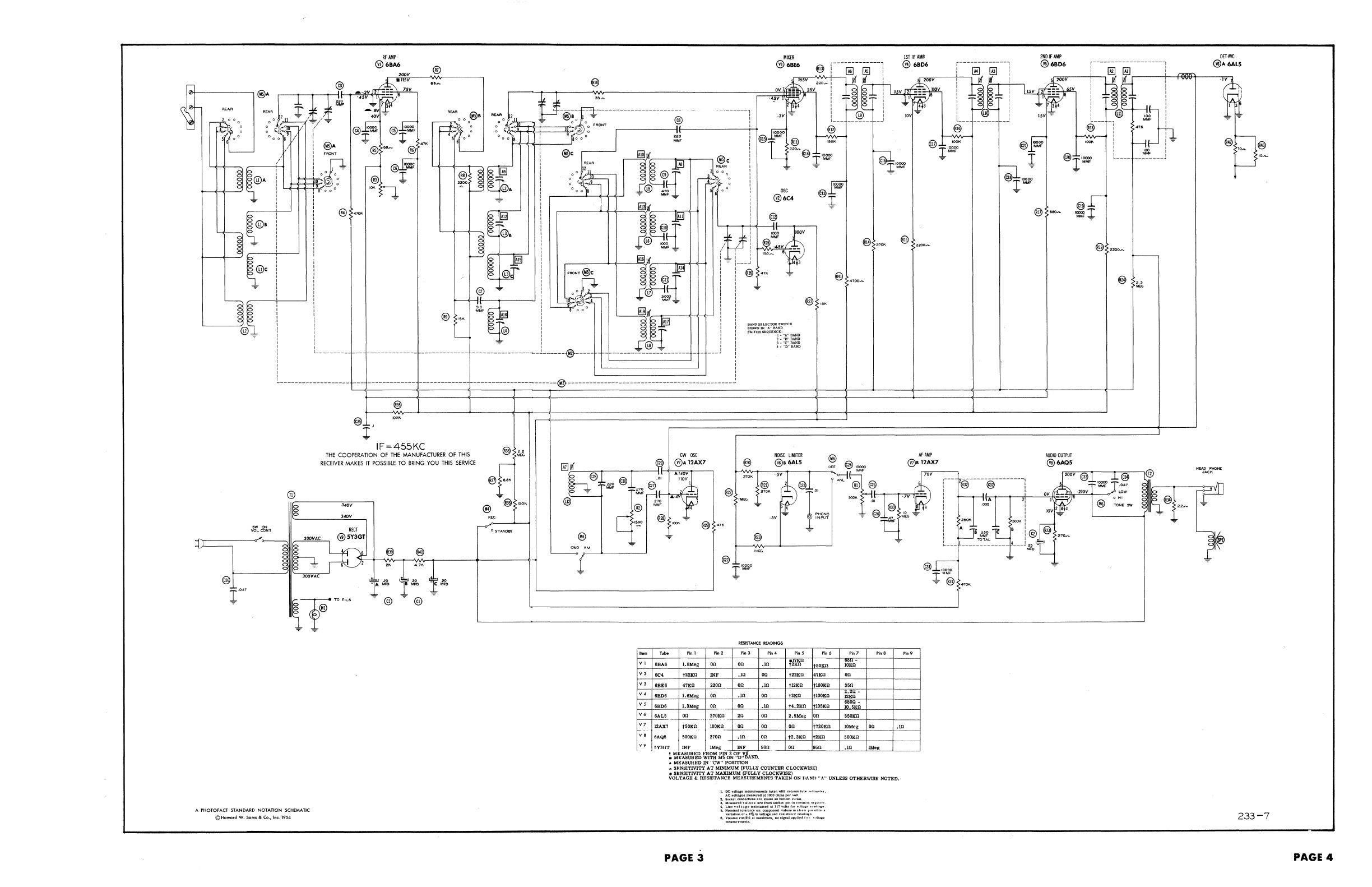
RfAMl'
@6BA6
200V
@
..
~
MIXER
@6BE6
1ST
IF
AM~
@l
i----~--[ill---l
@
6B.rD6-;;;;;,,-_-+r_--_-...,-~--@J---l
-:---------~;::::::;
....
;::.;
.•
:':;tf'f"§I:~m~
i
~
[~~
ii,
~~UI'
-;:-
:~.
tJ~;r:~~r-----------------------------@II~-----·---------_--_-_li-
I
.,
'r::
.
~~~
~~~
j
JF
8~
~
~,
00,
!
'1000
~:.
@.~
~
~
§~
!@CJI!i!lji(I----,........----,'M"C
@
I'~~~
~
I'::''',!'
~
i
'EAR
h
J,~
J~R
,..
~
~'=
'~j~~A
i
r--_~:_:~-'o~'_I_++-+_'
,..@:{
~6°~::
,@o:u@F
~
!
r-
___
-+11-+-+-_-'~=::A11
in'\_-_=__+_+
i 1
'--+---+---.1
~
tt
I
}Jt{:)
i
~!
~
~tbf
I
-~
rL~
t~·~
'f
®
15K
@
~
I
oi}-
@e{{
I
~
M~
~
I ~;o
~ji('r-~=--~~~~
i
:'~[
I I
~~
0 '
@)
:
I-!
BAND
SELECTOR
I!Wl1'CB
SHOWN
IN
"A"
BAND
SWITCH
SEQUENCE:
1·
"A"
BAND
2 _
"8"
BAND
@
15K
!
~l~:
~
i :
-------------
__________________
1
______
@-
_____
- -
---------~--::--------
- -
~---.
i
~:':.~:'.=
IF=455KC
I
,
,
----------------------@----------------------------------------------~
THE
COOPERATION
OF
THE
MANUFACTURER
OF
THIS
RECEIVER
MAKES
IT
POSSIBLE
TO
BRING
YOU
THIS
SERVICE
@i
"
Mro
AI'
AMP
@a12AX7
SW
ON
VOL CONT
®
lOOVAC
~Ih
I-----~
lOOVAC
S40V
l40V
REeT
@5Y3GT
~
---r®
TO
FILS
'1
r®
-::-
-=F
A PHOTOfACT
STANDARD
NOTAnON
SCHEMATIC
©Howard W. Sams & Co., Inc. 1954
r-<""
0 STANOB't
....
VI
V2
v,
V4
V5
V6
r--
V7
v 8
V9
RESISTANCE
READINGS
,
....
PI."
PI,2
PI,'
PI,4
""5
.....
.BA.
I.Bldeg
00
OD
.m
ffllfl"
.=
6C4
j22Kn
INF
.m
o.
to=
471:0
6BE6
4=
..
0.
00
.Ill
t12KD
t160m
.BDO
1.6Mog
00
.10
on
t'''''
tlOOKn
6BD6
I.SMag
on
...
on
.10
I
t4.'Ko
tlO5KQ
~.-.
on
r--"
270m
On
on
B.5Meg
on
l2AX7
t5.0K~_
lOOKO
00
On
on
t720KO
OAQ'
500KU
2700
.10
00
t2.3KO
to""
6Y30T
INY lMeS
.-
INF
900_"
on
95.
~
':t~'l\VJ:lil&
~Wt1l;rot
qro·Y&.ND
.
.f.
MICASU1tED IN "CW"
POSITION
..
SKN81'rlVlTY
AT
MINIMUM
(FULLY
COUNTER CLOCKWISE)
•
SICNSITMTY
AT
MAXIMUM
(FULLY
CLOCKWISE)
""'7
""8
PI,
•
~,*n-
on
35.
i:-
f:°:!cn
..
=
lOMeg
OD
.10
50QKO
.ill
lMeg
VOLTAGE
&
RESISTANCE
MEASUREMENTS
TAKEN
ON
HANn
"A"
UNLESS
OTHERWISE
NOTED.
PAGE
3
1.
DC
voltll8e melLllllremerlia t""en with
neuum
rub
...
"rrn,.IN,
ACvollaguQteaSlll'edatlOOOohmapervulr.
2.
lluckl!l
eon1lltctimBaN
aholm
lUI
bottom ylvwa,
3.
Me
...
"rO'd
yaluea
arefromaoeket
pin
I"~"n'n""'
"
.......
.
~.
L.I~~
yolta!:e
J(la\lItalnad
lit
II'
voila
lor
.,,11l1li"
.....
,,''11.
5. Nominal toler;lJl(e
on
comPORent Vailll!8
mak~"
I,,,~~,
..
t~
~
...
laIlnnol
..
l,.,lnvoltapandrea1.t.l'C
.....
oIl
....
s.
~!i::~~
..
t.:!~
at maxilll\llll, noBill"..L .ppllod
I",
.,,11
...
2ND
IF
AMP
DEl·Ave
@ 6BD6
r-------------------,
®
..
6AL5
r-..""--..;l-..,lm@].----1!_-I""""':.eGI9-1
___
"""
l~i'ff
I t
lt~L
.~'V.l
~~!I
I-SV"'='"
!
@.
I~~
~
I
MMF
@---
-1
47K
, ,
~
l
____
jt_J
~
8
tl
~
@l'~
~
@)
.-
AUDro
OUTPUT
@6AQ5
..,
....
HEM
PHON<
JACK
233-7
PAGE 4