National Instruments NI DIDS-2003 User manual

National Instruments Direct Injector Driver System
NI DIDS-2003
NI DIDS-2006
NI DIDS-2009
NI DIDS-2012
NI Direct Injector Driver System User Guide
May 2014

National Instruments Direct Injector Driver System Manual
© 2013 National Instruments. All rights reserved.
Table of Contents
National Instruments Direct Injector Driver System .......................................................................................4
1. About the NI Direct Injector Driver System .........................................................................................5
2. Warnings ...............................................................................................................................................6
2.1 REVERSE BATTERY POLARITY WARNING ..............................................................................7
2.2 HIGH VOLTAGE WARNING ........................................................................................................8
3. Getting Started .....................................................................................................................................9
3.1 What Is Included ........................................................................................................................10
3.2 Software ......................................................................................................................................12
3.2.1 SCM Software Installation .................................................................................................13
3.2.2 Connecting To The DI Driver System ...............................................................................17
3.2.2.1 Out Of The Box Connection ....................................................................................18
3.2.2.2 Changing The Network Settings Of The DI Driver System ......................................24
3.2.2.3 Manually Resetting The Controller Network Interface To DHCP ..............................26
3.2.2.4 SCM and Windows Firewall .....................................................................................30
3.2.3 Updating DI Driver System Controller Software ...............................................................35
3.2.4 Backing Up the DI Driver System Software Image ...........................................................37
3.2.5 Restoring A Backup Image To The DI Driver System Controller ......................................39
3.3 Hardware ....................................................................................................................................42
3.3.1 C-Series Module Slot Assignments ..................................................................................43
3.3.2 Powering the System ........................................................................................................45
3.3.3 Connecting Injectors, Sensors and Actuators ...................................................................47
3.3.3.1 Direct Injectors to DI Driver Channels .....................................................................48
3.3.3.2 Port Fuel Injectors to PFI Channels .........................................................................50
3.3.3.3 Proportional Solenoid Valves to PFI Lowside Channels ..........................................52
3.3.3.4 Digital Signals to NI 9411 Digital Input Module ........................................................53
3.3.3.5 Analog Signals to NI 9215 Analog Input Module .....................................................56
3.3.4 DI Driver System Component User Manual Reference ....................................................57
3.4 Using DI Driver System to Control Fuel Pressure .....................................................................58
3.5 Optimizing The DI Driver System ..............................................................................................60
4. NI Direct Injector Driver System Interface .........................................................................................61
4.1 DI Driver Setup Window ............................................................................................................63
4.1.1 DI Driver Scope Window ...................................................................................................73
4.2 PFI and LS Driver Setup Window ..............................................................................................74
4.2.1 PFI Module Control Tab ....................................................................................................75
4.2.2 PFI 1-4 Tab .......................................................................................................................79
4.2.3 LS 1-4 Tab .........................................................................................................................81
4.3 Digital Input Setup Window ........................................................................................................86
4.4 Analog Input Setup Window ......................................................................................................90
4.5 Pulse Generation Setup Window ...............................................................................................93
4.5.1 DI-TMP Tab .......................................................................................................................94
4.5.2 DI-EPT Tab ........................................................................................................................97
4.5.2.1 DI Advanced Settings Window ...............................................................................102
4.5.3 PFI Tab ............................................................................................................................106
4.6 Engine Position Tracking Setup Window .................................................................................110
4.6.1 EPT Tab ...........................................................................................................................120
4.6.2 TDC Channel Mapping Tab ............................................................................................130
National Instruments Direct Injector Driver System Manual
© 2013 National Instruments. All rights reserved.
4.6.3 Cam Phase Capture Tab ................................................................................................134
4.6.4 EPT Diagnostics Tab .......................................................................................................137
4.7 Calibration Mode Setup Window ..............................................................................................140
4.8 Table Setup Window ................................................................................................................143
4.8.1 Table1D ............................................................................................................................144
4.8.2 Table2D ............................................................................................................................147
4.8.3 User Variables .................................................................................................................150
4.9 Auxiliary PID Controller Setup Window ...................................................................................151
4.10 Rail Pressure Control Setup Window ....................................................................................157
4.11 Auxiliary PWM Setup Window ................................................................................................170
4.12 Operating Point Setup Window ..............................................................................................173
4.13 Active Flex Control Parameters Window ...............................................................................180
4.14 CalScopes ..............................................................................................................................181
4.15 CalTrends ...............................................................................................................................182
4.16 Log Data Setup Window ........................................................................................................183
4.17 Faults Window ........................................................................................................................188
4.18 Execution Information Window ...............................................................................................192
4.18.1 Static Info ......................................................................................................................193
4.18.2 Network ..........................................................................................................................194
4.18.3 Run-Time Info ................................................................................................................195
5. Troubleshooting ................................................................................................................................196
6. Diagrams ..........................................................................................................................................197
7. Additional Support/Feedback ...........................................................................................................207
8. Important Information .......................................................................................................................208
8.1 Warranty ...................................................................................................................................209
8.2 Copyright ..................................................................................................................................210
8.3 Trademarks ...............................................................................................................................211
8.4 Patents ......................................................................................................................................212
8.5 Warning Regarding Use of NI Products ..................................................................................213
8.6 Environmental Management ....................................................................................................214

National Instruments Direct Injector Driver System Manual
© 2013 National Instruments. All rights reserved.
National Instruments Direct Injector Driver System
NI DIDS-2003
NI DIDS-2006
NI DIDS-2009
NI DIDS-2012
NI Direct Injector Driver System User Guide
May 2014

National Instruments Direct Injector Driver System Manual
© 2013 National Instruments. All rights reserved.
1. About the NI Direct Injector Driver System
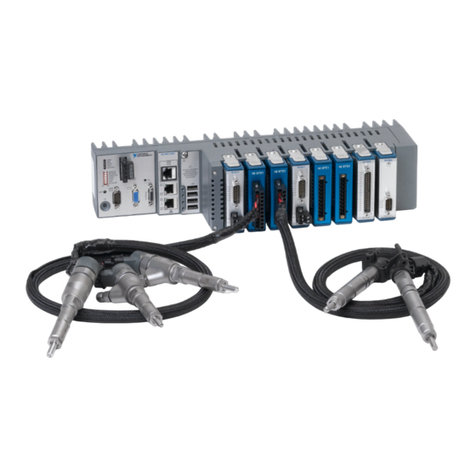
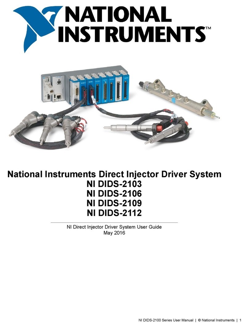
The NI Direct Injector Driver System features an NI CompactRIO controller, NI 9751 Direct Injector (DI) driver
module(s), and NI 9411 digital input module(s). The system can synchronize injector channels with production
crank/cam position sensors or research optical encoders. The system will also accept external digital fuel command
signals from a production engine controller. The included DI driver module(s) provide the power electronics
necessary to drive high-power solenoid or piezoelectric direct injectors.
The NI Direct Injector Driver System comes in four different models corresponding to different direct injector channel
configurations: the NI DIDS-2003 drives 3 solenoid injectors (or 2 piezoelectric injectors), the NI DIDS-2006 drives
6 solenoid injectors (or 4 piezoelectric injectors), the NI DIDS-2009 drives 9 solenoid injectors (or 6 piezoelectric
injectors), and the NI DIDS-2012 drives 12 solenoid injectors (or 8 piezoelectric injectors). The systems provide a
digital input per injector channel for directly commanding each injector. The system controller is delivered with a pre-
installed feature-rich application. The deployment version of the NI Software Calibration Manager Toolkit (SCM) is
included for interfacing with and calibrating the system.
The NI Direct Injector Driver System supports optional C-series modules. The optional NI 9758 PFI driver module
can be used to drive port fuel injectors, proportional solenoid valves and relays. The optional NI 9215 analog input
module can be used for a variety of analog sensors. Common-rail fuel pressure control is an example feature of the
NI Direct Injector Driver System that utilizes these modules.
Throughout this manual, the model number NI 9751 and model name DI Driver module are used interchangeably.
Similarly, the model number NI 9758 and model name PFI Driver are used interchangeably.

National Instruments Direct Injector Driver System Manual
© 2013 National Instruments. All rights reserved.
2. Warnings
Please read the following warnings for your safety and that of the product.

National Instruments Direct Injector Driver System Manual
© 2013 National Instruments. All rights reserved.
2.1 REVERSE BATTERY POLARITY WARNING
NI Powertrain Controls power modules are not internally protected against reverse battery polarity.
Do not reverse the battery polarity or damage will occur. This event is not covered under warranty.
All NI Powertrain Controls modules with a 10-pin screw terminal block have identical external
power and ground connections. Please take necessary precautions to ensure that BATT (0)
and GND (9) are not connected in reverse polarity. The BATT (0) terminal will accept positive
7-32VDC with respect to the GND (9) terminal. Please refer to the user manual for details.
To provide system-level protection against reverse battery polarity, implement the following simple external
main-power-relay circuit:
Figure 2.1.a, Reverse Battery Protection Diagram
Notes:
1.) The relay shown is a type of automotive relay which includes an internal series diode with terminal 85. This diode
will prevent reverse battery from energizing the relay.
2.) Terminals 30 and 87 are screw terminals and should be connected with soldered ring terminals.
3.) Terminals 85 and 86 are 0.250 X 0.031 inch (6.3 X 0.8 mm) push-on terminals.
4.) A fuse is recommended between the battery and relay.
5.) An optional switch may be placed in series with relay terminal 86.
6.) Simply placing a high-current-capacity diode in series with the system power is not an acceptable method
of reverse battery protection because it will not allow the NI Powertrain Controls modules to perform current
recirculation while switching inductive loads.
7.) The relay is currently available from www.ni.com.

National Instruments Direct Injector Driver System Manual
© 2013 National Instruments. All rights reserved.
2.2 HIGH VOLTAGE WARNING
HIGH VOLTAGE: This device is capable of operating at voltages up to 190V. Extreme care should
be taken to protect against shock. Even when the device is completely powered down, allow
approximately five minutes for the internal high voltage to dissipate. Do not touch any of the driver
module screw terminals or injector terminals while the device is powered.

National Instruments Direct Injector Driver System Manual
© 2013 National Instruments. All rights reserved.
3. Getting Started
This guide will provide instructions to set up the National Instruments Direct Injector Driver System hardware and
software.

National Instruments Direct Injector Driver System Manual
© 2013 National Instruments. All rights reserved.
3.1 What Is Included
Software
1. DI Driver System software image preinstalled on the system controller
2. NI Software Calibration Management Toolkit (SCM) for LabVIEW 2013, downloaded from www.ni.com.
Hardware
1. Direct Injector Driver System
DI Driver System
cRIO-9076
Integrated
Controller
and Chassis
781716-01
cRIO-9022
Controller
780718-01
cRIO-9114
Chassis
780918-01
NI 9411
Digital Input
Module
779005-01
NI 9751
DI Driver
Module
782076-01
DIDS-2003 1 1 1
DIDS-2006 1 1 1 2
DIDS-2009 1 1 2 3
DIDS-2012 1 1 2 4
Table 3.1.a, I/O Hardware Included In The DI Driver System
Optional I/O modules supported by all DI Driver Systems
• NI 9215 4-Channel, 100 kS/s/ch, 16-bit, ±10 V Analog Input Module (P/N: 779011-01)
• NI 9758 PFI Driver Module (P/N: 782080-01)
2. Piezo Injector Inductors (P/N: 782082-01)
Piezo Injector Inductor Packs
Included In Each DI Driver System
DI Driver System Number of Inductors
DIDS-2003 2 (1 pack)
DIDS-2006 4 (2 packs)
DIDS-2009 6 (3 packs)
DIDS-2012 8 (4 packs)
Table 3.1.b, Number of Inductors Included With The DI Driver System

National Instruments Direct Injector Driver System Manual
© 2013 National Instruments. All rights reserved.
3. Reverse Battery Protection Relay (P/N: 782784-01)
4. NI 9411 Module Breakout Harness(es) per NI 9411 Module (P/N: 782784-01)

National Instruments Direct Injector Driver System Manual
© 2013 National Instruments. All rights reserved.
3.2 Software

National Instruments Direct Injector Driver System Manual
© 2013 National Instruments. All rights reserved.
3.2.1 SCM Software Installation
Software Download
At the time of shipping, the DI Driver System controller is pre-programmed with the latest version of software.
However, in order to interact with the system, NI Software Calibration Management Toolkit (SCM) must be
downloaded and installed to a PC with Windows 7 or newer. To download SCM follow the link below.
Download SCM Software
The link will take you to this webpage; click on download to begin the download process.
Enter your NI User Account information as directed. If you do not have an NI User Account, create one for free and
then proceed.

National Instruments Direct Injector Driver System Manual
© 2013 National Instruments. All rights reserved.
Download the LabVIEW 2013 version of the software. When prompted, choose the option to save the file
NI_SCM_2013.zip.

National Instruments Direct Injector Driver System Manual
© 2013 National Instruments. All rights reserved.
Software Installation
After the download is complete, browse to the location on disk where the file was saved. Extract the contents of
the .zip file.
After extracting the file, open the created directory and run the Setup.exe application. If prompted, install
Microsoft .NET Framework 4.0.
When prompted at the User Information screen, enter the relevant information and select the option to install the
evaluation version of the license. The evaluation license is a free, perpetual license of SCM that allows users to
interface to SCM-supported targets, but does not allow them to modify any code.

National Instruments Direct Injector Driver System Manual
© 2013 National Instruments. All rights reserved.
From there, follow the instructions and prompts to finish installing the software.

National Instruments Direct Injector Driver System Manual
© 2013 National Instruments. All rights reserved.
3.2.2 Connecting To The DI Driver System
This section provides information about connecting to the DI Driver System user interface via SCM and how to
change the network interface settings of the system controller.

National Instruments Direct Injector Driver System Manual
© 2013 National Instruments. All rights reserved.
3.2.2.1 Out Of The Box Connection
This section describes how to establish a connection with the DI Driver System user interface via SCM. NI ships the
DI Driver System with an IP address of 192.168.1.100 and a Subnet mask of 255.255.255.0. The Windows PC used
to interface with the system must have a similar IP address and Subnet mask, but the IP address must be different in
the last address number. The directions below illustrate how to make the initial network connection to the system and
open the system user interface.
1. The customer must provide a Windows 7 (or later) PC with an Ethernet LAN port.
2. Install SCM for LabVIEW 2013 to the PC.
3. Check the Windows Firewall settings or 3rd party firewall settings to allow SCM to communicate with the external
system.
4. Power up the DI Driver System controller. The DI Driver and PFI Driver modules do not need to be powered if
simply attempting to establish a connection to the user interface. Wait about 1 minute for both the USER1 and
USER FPGA LEDs to start blinking.
5. Using a CAT5E Ethernet cable, connect the Windows PC LAN port directly to the Ethernet port of the cRIO-9076
or Ethernet port 1 of the cRIO-9022 controller. If the green and amber LEDs directly under the controller Ethernet
port are not active, then there is no physical Ethernet connection to the PC. Please diagnose the Ethernet cable
connection problem.
6. Go to the Windows Control Panel and select Network and Sharing Center. From the Network and Sharing
Center select Change adapter settings from the left menu.
7. A list of network connections available on the PC will open. Right click the Local Area Connection port to select
Properties.

National Instruments Direct Injector Driver System Manual
© 2013 National Instruments. All rights reserved.
8. From the Local Area Connection Properties dialog, scroll down to select Internet Protocol Version 4 (TCP/
IPv4) and select the Properties button below the scroll window.
9. From the Internet Protocol Version 4 (TCP/IPv4) Properties dialog, select the Use the following IP address
radio button. Enter 192.168.1.101 for the IP address: field. Enter 255.255.255.0 for the Subnet mask: field. Select
OK on the Internet Protocol Version 4 (TCP/IPv4) Properties dialog and the Local Area Connection Properties
dialog to accept the IP address changes.

National Instruments Direct Injector Driver System Manual
© 2013 National Instruments. All rights reserved.
10. Open the NI SCM console from the Windows Start menu under National Instruments >> Software
Calibration Management.
11. Within the SCM console, right-click inside the Target Items list pane and select Select Target.
This manual suits for next models
3
Table of contents
Other National Instruments Laboratory Equipment manuals

National Instruments
National Instruments PXI-1002 User manual

National Instruments
National Instruments NI EDIDS-2400 Series User manual

National Instruments
National Instruments NI DIDS-2103 User manual

National Instruments
National Instruments IMAQ PXI-1409 User manual

National Instruments
National Instruments SCXI-1141 Manual

National Instruments
National Instruments NI VB-8012 Owner's manual