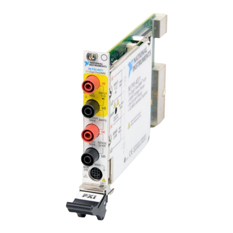
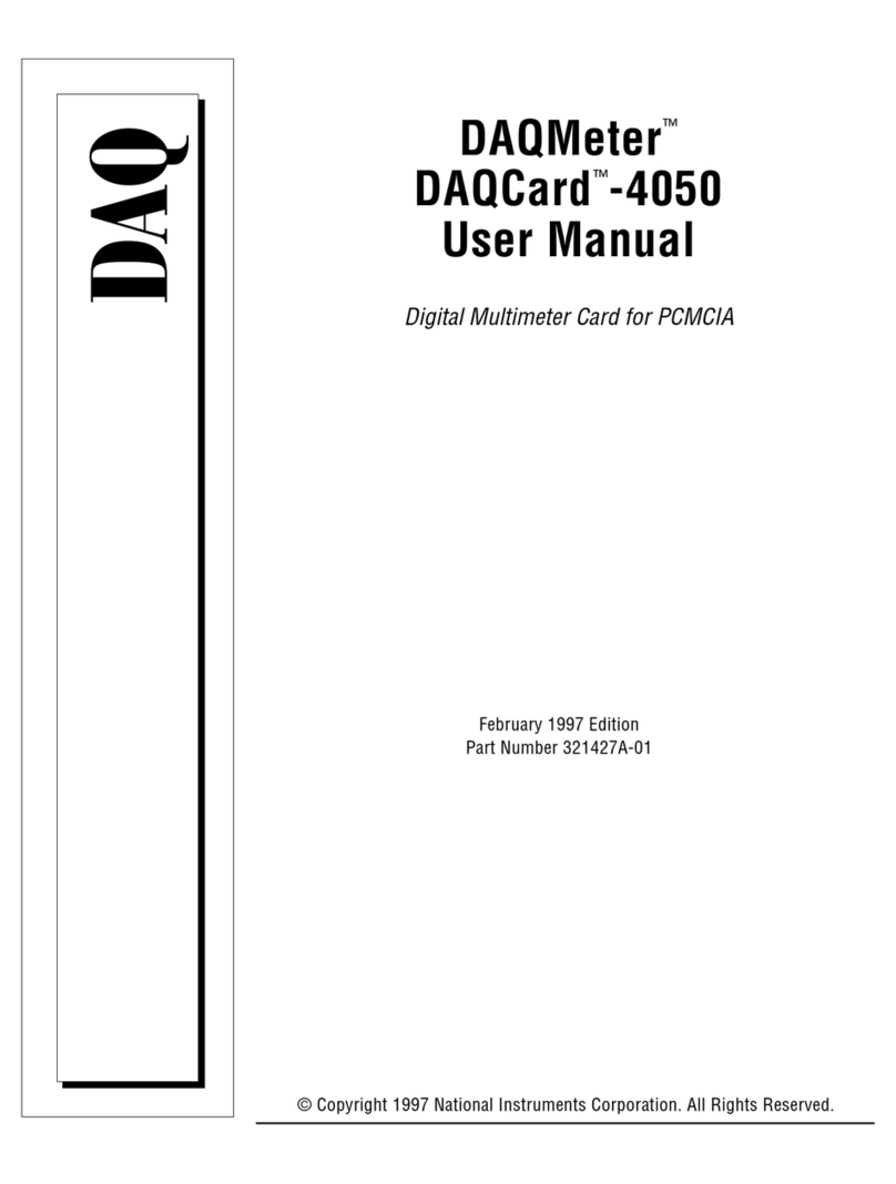
National Instruments NI PCMCIA-4050 User manual

©2002 National Instruments Corp. All rights reserved.
CVI™, LabVIEW™, National Instruments™, NI™, and ni.com™ are trademarks of National Instruments Corporation.
Product and company names mentioned herein are trademarks or trade names of their respective companies. For patents
covering National Instruments products, refer to the appropriate location: Help»Patents in your software, the
patents.txt file on your CD, or ni.com/patents.
July 2002
323120A-01
NI DIGITAL MULTIMETERS GETTING STARTED GUIDE
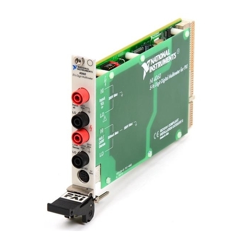
NI PCMCIA-4050, NI PXI/PCI-4060, NI PXI-4070
Contents
Conventions ............................................................................................ 2
Introduction............................................................................................. 2
FCC/Canada Radio Frequency Interference Compliance....................... 3
Safety Instructions................................................................................... 5
Getting Started ........................................................................................ 8
Unpacking ............................................................................................... 8
Installing the Software ............................................................................ 9
Installing the Hardware ........................................................................... 9
PXI Installation ................................................................................ 10
PCI Installation ................................................................................ 11
PCMCIA Installation ....................................................................... 12
Configuration in MAX............................................................................ 13
Connecting Signals ................................................................................. 14
PXI/PCI............................................................................................ 14
PCMCIA .......................................................................................... 15
Using Cable and Probes .......................................................................... 16
Wiring for Common Measurements ....................................................... 16
DC and AC Voltage......................................................................... 17
DC and AC Current ......................................................................... 18
2-Wire Resistance ............................................................................ 19
4-Wire Resistance ............................................................................ 20
Voltage Drop across a Diode ........................................................... 21
Temperature ..................................................................................... 22
Acquiring Data ........................................................................................ 23
DMM Soft Front Panel .................................................................... 23
NI-DMM Instrument Driver ............................................................ 23
Fuse Replacement ................................................................................... 23
NI PXI/PCI-4060 ............................................................................. 24
NI PXI-4070 .................................................................................... 26
ni.com

NI Digital Multimeters Getting Started Guide 2 ni.com
Conventions
The following conventions are used in this manual:
»The »symbol leads you through nested menu items and dialog box options
to a final action. The sequence File»Page Setup»Options directs you to
pull down the File menu, select the Page Setup item, and select Options
from the last dialog box.
♦The ♦symbol indicates that the following text applies only to a specific
product, a specific operating system, or a specific software version.
This icon denotes a tip, which alerts you to advisory information.
This icon denotes a note, which alerts you to important information.
This icon denotes a caution, which advises you of precautions to take to
avoid injury, data loss, or a system crash.
bold Bold text denotes items that you must select or click in the software, such
as menu items and dialog box options. Bold text also denotes parameter
names and information on hardware labels.
DMM Digital multimeter—refers to either the NI PCMCIA-4050, NI PCI-4060,
NI PXI-4060, or NI PXI-4070 unless specified otherwise.
italic Italic text denotes variables, emphasis, a cross reference, or an introduction
to a key concept. This font also denotes text that is a placeholder for a word
or value that you must supply.
monospace Text in this font denotes text or characters that you should enter from the
keyboard, sections of code, programming examples, and syntax examples.
This font is also used for the proper names of disk drives, paths, directories,
programs, subprograms, subroutines, device names, functions, operations,
variables, filenames and extensions, and code excerpts.
Introduction
This document explains how to install, configure, test, and set up a National
Instruments digital multimeter (DMM) for common measurements. For
more information on the DMM, such as features and programming, refer to
NI Digital Multimeters Help at Program Files»National Instruments»
NI-DMM»Documentation»NI Digital Multimeters Help.
Detailed specifications about your DMM are available in the specifications
guide included with your DMM module.

©National Instruments Corporation 3 NI Digital Multimeters Getting Started Guide
For free downloads of the most current versions of manuals and example
programs, visit ni.com/instruments.
FCC/Canada Radio Frequency Interference Compliance
1
Determining FCC Class
The Federal Communications Commission (FCC) has rules to protect
wireless communications from interference. The FCC places digital
electronics into two classes. These classes are known as Class A (for use
in industrial-commercial locations only) or Class B (for use in residential
or commercial locations). Depending on where it is operated, this product
could be subject to restrictions in the FCC rules. (In Canada, the
Department of Communications (DOC), of Industry Canada, regulates
wireless interference in much the same way.)
Digital electronics emit weak signals during normal operation that can
affect radio, television, or other wireless products. By examining the
product you purchased, you can determine the FCC Class and therefore
which of the two FCC/DOC Warnings apply in the following sections.
(Some products may not be labeled at all for FCC; if so, the reader should
then assume these are Class A devices.)
FCC Class A products only display a simple warning statement of one
paragraph in length regarding interference and undesired operation. Most
of our products are FCC Class A. The FCC rules have restrictions regarding
the locations where FCC Class A products can be operated.
FCC Class B products display either a FCC ID code, starting with the
letters EXN, or the FCC Class B compliance mark that appears as shown
below.
Consult the FCC Web site at http://www.fcc.gov for more
information.
FCC/DOC Warnings
This equipment generates and uses radio frequency energy and, if not
installed and used in strict accordance with the instructions in this manual
and the CE Mark Declaration of Conformity2, may cause interference to
1 Certain exemptions may apply in the USA, see FCC Rules §15.103 Exempted devices, and §15.105(c). Also available in
sections of CFR 47.

NI Digital Multimeters Getting Started Guide 4 ni.com
radio and television reception. Classification requirements are the same
for the Federal Communications Commission (FCC) and the Canadian
Department of Communications (DOC).
Changes or modifications not expressly approved by National Instruments
could void the user’s authority to operate the equipment under the
FCC Rules.
Class A
Federal Communications Commission
This equipment has been tested and found to comply with the limits for a
Class A digital device, pursuant to part 15 of the FCC Rules. These limits
are designed to provide reasonable protection against harmful interference
when the equipment is operated in a commercial environment. This
equipment generates, uses, and can radiate radio frequency energy and,
if not installed and used in accordance with the instruction manual, may
cause harmful interference to radio communications. Operation of this
equipment in a residential area is likely to cause harmful interference
in which case the user will be required to correct the interference at his
own expense.
Canadian Department of Communications
This Class A digital apparatus meets all requirements of the Canadian
Interference-Causing Equipment Regulations.
Cet appareil numérique de la classe A respecte toutes les exigences du
Règlement sur le matériel brouilleur du Canada.
Class B
Federal Communications Commission
This equipment has been tested and found to comply with the limits for a
Class B digital device, pursuant to part 15 of the FCC Rules. These limits
are designed to provide reasonable protection against harmful interference
in a residential installation. This equipment generates, uses, and can radiate
radio frequency energy and, if not installed and used in accordance with the
instructions, may cause harmful interference to radio communications.
However, there is no guarantee that interference will not occur in a
particular installation. If this equipment does cause harmful interference
to radio or television reception, which can be determined by turning the
2 The CE Mark Declaration of Conformity will contain important supplementary information and instructions for the user or
installer.

©National Instruments Corporation 5 NI Digital Multimeters Getting Started Guide
equipment off and on, the user is encouraged to try to correct the
interference by one or more of the following measures:
• Reorient or relocate the receiving antenna.
• Increase the separation between the equipment and receiver.
• Connect the equipment into an outlet on a circuit different from that
to which the receiver is connected.
• Consult the dealer or an experienced radio/TV technician for help.
Canadian Department of Communications
This Class B digital apparatus meets all requirements of the Canadian
Interference-Causing Equipment Regulations.
Cet appareil numérique de la classe B respecte toutes les exigences du
Règlement sur le matériel brouilleur du Canada.
Compliance to EU Directives
Readers in the European Union (EU) must refer to the Manufacturer’s
Declaration of Conformity (DoC) for information1pertaining to the
CE Mark compliance scheme. The Manufacturer includes a DoC for most
every hardware product except for those bought for OEMs, if also available
from an original manufacturer that also markets in the EU, or where
compliance is not required as for electrically benign apparatus or cables.
To obtain the DoC for this product, click Declaration of Conformity at
ni.com/hardref.nsf/. This Web site lists the DoCs by product family.
Select the appropriate product family, followed by your product, and a link
to the DoC appears in Adobe Acrobat format. Click the Acrobat icon to
download or read the DoC.
Safety Instructions
This section contains important safety instructions that you must follow
when installing and using the product.
Do not operate the product in a manner not specified in the product
documentation. Misuse of the product can result in a hazard. You can
compromise the safety protection built into the product if the product is
damaged in any way. If the product is damaged, return it to National
Instruments for repair.
1 The CE Mark Declaration of Conformity will contain important supplementary information and instructions for the user or
installer.

NI Digital Multimeters Getting Started Guide 6 ni.com
Do not substitute parts or modify the product except as described in the
product documentation.
Do not operate the product in an explosive atmosphere or where there may
be flammable gases or fumes. Operate the product only at or below the
pollution degree stated in the hardware specifications. Pollution is foreign
matter in a solid, liquid, or gaseous state that can reduce dielectric strength
or surface resistivity. The following is a description of pollution degrees:
• Pollution degree 1 means that no pollution or only dry, nonconductive
pollution occurs. The pollution has no influence.
• Pollution degree 2 means that only nonconductive pollution occurs in
most cases. Occasionally, however, condensation can cause temporary
conductivity.
• Pollution degree 3 means that conductive pollution occurs, or dry,
nonconductive pollution occurs that becomes conductive due to
condensation.
Clean the product with a soft nonmetallic brush. Make sure the product is
completely dry and free from contaminants before returning it to service.
You must insulate signal connections for the maximum voltage for which
the product is rated. Do not exceed the maximum ratings for the product.
Remove power from signal lines before connecting them to or
disconnecting them from the product.
Operate this product only at or below the installation category stated in the
hardware specifications.
The following is a description of installation categories:
• Installation Category I is for measurements performed on circuits not
directly connected to MAINS1. This category includes signals such as
voltages on a printed circuit board (PCB) on the secondary of an
isolation transformer.
Examples of Installation Category I are measurements on circuits
not derived from MAINS and on specially protected (internal)
MAINS-derived circuits.
• Installation Category II is for measurements performed on circuits
directly connected to the low-voltage installation. This category refers
to local-level distribution such as that provided by a standard wall
outlet.
1 MAINS is defined as the electricity supply system to which the equipment concerned is designed to be connected either for
powering the equipment or for measurement purposes.

©National Instruments Corporation 7 NI Digital Multimeters Getting Started Guide
Examples of Installation Category II are measurements on household
appliances, portable tools, and similar equipment.
• Installation Category III is for measurements performed in the building
installation. This category is a distribution level referring to hardwired
equipment that does not rely on standard building insulation.
Examples of Installation Category III include measurements on
distribution circuits and circuit breakers. Other examples of
Installation Category III are wiring including cables, bus-bars, junction
boxes, switches, socket outlets in the building/fixed installation, and
equipment for industrial use, such as stationary motors with a
permanent connection to the building/fixed installation.
• Installation Category IV is for measurements performed at the source
of the low-voltage (<1,000 V) installation.
Examples of Installation Category IV are electric meters, and
measurements on primary overcurrent protection devices and on
ripple-control units.
Below is a diagram of a sample installation.
Refer to the specifications guide included with the DMM to determine the
pollution and installation categories of the DMM.

NI Digital Multimeters Getting Started Guide 8 ni.com
Getting Started
To set up and use the DMM, you need the following:
❑NI PCMCIA-4050 (NI 4050), NI PXI/PCI-4060 (NI 4060), or
NI PXI-4070 (NI 4070)
❑NI-DMM driver software
Note The NI PXI-4070 requires NI-DMM 2.0 or later.
❑NI Digital Multimeters Getting Started Guide
❑NI Digital Multimeters Help located at Program Files»National
Instruments»NI-DMM»NI Digital Multimeters Help
❑The specifications guide included with your DMM module.
❑A PXI chassis and controller, desktop computer, or a laptop with a
PCMCIA slot
❑1/8 in. flathead screwdriver
❑One of the following software packages and documentation:
–NILabVIEW
–LabWindows/CVI
– Microsoft Visual C++
– Microsoft Visual Basic
Unpacking
The DMM ships in an antistatic package to prevent electrostatic damage.
Electrostatic discharge can damage several components on the DMM.
Caution Never touch the exposed pins of connectors.
To avoid damage in handling the DMM, take the following precautions:
1. Ground yourself using a grounding strap or by holding a grounded
object.
2. Touch the antistatic package to a metal part of your computer chassis
before removing the DMM from the package.

©National Instruments Corporation 9 NI Digital Multimeters Getting Started Guide
Remove the DMM from the package and inspect it for loose components or
any sign of damage. Notify NI if the DMM appears damaged in any way.
Do not install a damaged DMM into your computer or chassis.
Store the DMM in the antistatic envelope when not in use.
Installing the Software
Complete the following steps to install the software before installing
the DMM.
1. Install an application development environment (ADE) such as
LabVIEW, LabWindows/CVI, Microsoft Visual C++, or Microsoft
Visual Basic.
2. Install the NI-DMM instrument driver software according to the
instructions on the CD included with your DMM.
Installing the Hardware
Cautions Yo u must power off your PC or chassis before installing the DMM.
To prevent damage to the DMM due to electrostatic discharge or contamination, handle the
device using the edges or the metal bracket.
Note Install the NI-DMM software before installing the hardware.

NI Digital Multimeters Getting Started Guide 10 ni.com
PXI Installation
To install the PXI-DMM, refer to Figure 1 and complete the following
steps:
1. Power off the PXI chassis.
2. Slide the PXI-DMM into an available slot until the ejector handle locks
in the up position.
3. Secure the DMM with the screws provided.
4. Power on the PXI chassis.
Figure 1. PXI Installation
1 PXI Chassis
2 PXI-DMM
3Screw
4 Ejector Handle
8
7
6
5
4
3
2
1
ONSTANDBY
1
32
4

©National Instruments Corporation 11 NI Digital Multimeters Getting Started Guide
PCI Installation
To install the PCI-DMM, refer to Figure 2 and complete the following
steps:
1. Power off your PC and remove the cover.
2. Insert the PCI-DMM into an open PCI slot.
3. Secure the DMM with the screw provided.
4. Replace the PC cover.
5. Power on your computer.
Figure 2. PCI Installation
1PCISlot 2PCI-DMM 3 Desktop Computer
2
3
1

©National Instruments Corporation 13 NI Digital Multimeters Getting Started Guide
Configuration in MAX
1. Launch Measurement & Automation Explorer (MAX) to configure
and test the DMM. MAX detects the DMM you installed.
2. Double-click Devices and Interfaces to see the DMM listed. If the
device is not listed, press <F5>.
3. Right-click the DMM icon, and select Properties. Refer to the device
number and resources assigned to the DMM by MAX.
4. In the Configuring Device window, click Test Resources. A dialog
box appears and indicates if the DMM has passed the resource test.
Note If the device does not pass the test, power off the PC, remove the DMM, and repeat
the appropriate installation procedure. If the device still does not pass the test, visit our
support Web site at ni.com/support.
5. Click Run Test Panels to run the functional test panels and to use the
DMM. Refer to the Connecting Signals section to connect a signal to
the DMM.
Note The Run Test Panels option is currently not available for the NI 4070.
6. Click Close to close the Test Panel.
7. Click OK to close the Properties window and return to the MAX main
window.
8. Exit MAX.

NI Digital Multimeters Getting Started Guide 14 ni.com
Connecting Signals
This section discusses what connections are available on the DMM and
how to connect signals to the DMM.
PXI/PCI
Figure 4 shows the front panels for PXI and PCI devices. The PXI and PCI
front panels contain five connectors—four shrouded banana jacks and one
9-pin connector.
Figure 4. Connections on the PXI and PCI Devices
The four banana jacks are high-voltage, safety signal connectors. The 9-pin
connector labeled AUX I/O is a digital signal connector, which carries
1 NI PCI-4060
2 NI PXI-4060
3 NI PXI-4070
4 Banana Jack Connectors
5 9-Pin Connectors
U
O
S
A
NI
N
T
T
R
I
N
L
E
N
M
A
TS
NI PXI-4070
HI
LO
HI
LO
AUX I/O
1 A
250 V
MAX
5V
MAX
AMPS
INPUT
VΩ
SENSE
Ω4W
6½-Digit FlexDMM
300 V
MAX
CAT II
300 V
MAX
CAT II

©National Instruments Corporation 15 NI Digital Multimeters Getting Started Guide
TTL-level triggering signals for use with external scanning equipment.
Refer to the NI Digital Multimeters Help located at Program Files»
National Instruments»NI-DMM»NI Digital Multimeters Help for
information about scanning.
PCMCIA
The NI 4050 instrument kit contains the NI 4050 accessory cable that
connects the NI 4050 to a pair of test probes with shrouded banana jacks,
which are also included in the kit.
Connect the cable to the PCMCIA card as shown in Figure 5. The
accessory cable connector is polarized so that it cannot be plugged in
incorrectly.
Caution To measure current with the NI 4050, you must use a shunt. Refer to the DC and
AC Current section for more information.
Figure 5. Connecting Cables to the NI 4050
1 Laptop Computer
2 PCMCIA Slot
3 NI PCMCIA-4050
4 Accessory Cable
5 Test Probes
1
2
3
4
5

NI Digital Multimeters Getting Started Guide 16 ni.com
Using Cable and Probes
The DMM kit contains a pair of test probes with safety banana jacks. These
probes meet international safety requirements, including UL 3111 and
IEC 1010-1, for the full range of applications supported by the DMM.
Caution Before using any probes or accessories not supplied by NI, ensure that they meet
applicable safety requirements for the signal levels you may encounter.
Connect the test probes to the DMM using safety banana jacks. The
shrouds around the banana jacks prevent you from contacting potentially
hazardous voltages connected to the test probes. You also can connect the
cable to standard, unshrouded banana jack probes or accessories. Use
unshrouded probes or accessories only when the voltages are less than
30 Vrms and 42 Vpk, or 60 VDC.
Caution NI 4050 users—to prevent possible safety hazards, the maximum voltage
between either of the inputs and the ground of the computer should never exceed
±250 VDC or 250 Vrms.
Caution NI 4060/4070 users—to prevent possible safety hazards, the maximum voltage
between either of the inputs and the ground of the computer should never exceed
±300 VDC or 300 Vrms. The maximum current that the NI 4060 can measure between the
current inputs is ±200 mA DC or 200 mArms. The maximum current that the NI 4070 can
measure between the current inputs is ±1 A DC or 1 Arms.
Wiring for Common Measurements
The following sections explain how to wire your DMM for common
measurements. To learn more about these measurements refer to NI Digital
Multimeters Help at Program Files»National Instruments»NI-DMM»
NI Digital Multimeters Help.
Caution Always refer to the specifications guide included with your DMM before
connecting signals. Failure to observe the maximum signal ratings on the DMM can create
a shock or fire hazard or can damage any or all of the devices connected to the DMM. NI is
not liable for any damages or injuries resulting from incorrect signal connections.

©National Instruments Corporation 17 NI Digital Multimeters Getting Started Guide
DC and AC Voltage
Figure 6. NI 4050 Signal Connections for Voltage Measurements
Figure 7. NI 4060/4070 Signal Connections for Voltage Measurements
or
250 V
MAX.
LO
HI
+
–
U
O
S
A
NI
N
T
T
R
I
N
L
E
N
M
A
TS
!
HI
LO
250V
Max
HI
LO
AUX I/O
200mA
Max
250V
Max
5V
Max
V
Input
mA /
4W
Sense
U
O
S
A
NI
N
T
T
R
I
N
L
E
N
M
A
TS
NI PXI-4070
HI
LO
HI
LO
AUX I/O
1 A
250 V
MAX
5V
MAX
AMPS
INPUT
VΩ
SENSE
Ω4W
6½-Digit FlexDMM
300 V
MAX
CAT II
300 V
MAX
CAT II
or
+
–or
+
–

NI Digital Multimeters Getting Started Guide 18 ni.com
DC and AC Current
Figure 8. NI 4050 Signal Connections for Current Measurements
Note To measure current (up to 200 mA), the NI 4050 requires the CSM-200mA current
shunt module included with your NI 4050.
Figure 9. NI 4060/4070 Signal Connections for Current Measurements
Tip To measure current up to 10 A, NI provides an external shunt package (CSM-10A)
for your convenience. Refer to the CSM-10A and CSM-200mA Current Shunt Modules
Installation Guide included with your CSM-10A shunt for information. Refer to
ni.com/instruments for purchasing information.
250 V
MAX.
LO
HI
250 V
MAX.- FUSED
LO
HI
CSM-200MA
200MA SHUNT
U
O
S
A
NI
N
T
T
R
I
N
L
E
N
M
A
TS
!
HI
LO
250V
Max
HI
LO
AUX I/O
200mA
Max
250V
Max
5V
Max
V
Input
mA /
4W
Sense
U
O
S
A
NI
N
T
T
R
I
N
L
E
N
M
A
TS
NI PXI-4070
HI
LO
HI
LO
AUX I/O
1 A
250 V
MAX
5V
MAX
AMPS
INPUT
VΩ
SENSE
Ω4W
6½-Digit FlexDMM
300 V
MAX
CAT II
300 V
MAX
CAT II

©National Instruments Corporation 19 NI Digital Multimeters Getting Started Guide
2-Wire Resistance
Figure 10. NI 4050 Signal Connections for 2-Wire Resistance Measurements
Figure 11. NI 4060/4070 Signal Connections for 2-Wire Resistance Measurements
250 V
MAX.
LO
HI
U
O
S
A
NI
N
T
T
R
I
N
L
E
N
M
A
TS
!
HI
LO
250V
Max
HI
LO
AUX I/O
200mA
Max
250V
Max
5V
Max
V
Input
mA /
4W
Sense
U
O
S
A
NI
N
T
T
R
I
N
L
E
N
M
A
TS
NI PXI-4070
HI
LO
HI
LO
AUX I/O
1 A
250 V
MAX
5V
MAX
AMPS
INPUT
VΩ
SENSE
Ω4W
6½-Digit FlexDMM
300 V
MAX
CAT II
300 V
MAX
CAT II

NI Digital Multimeters Getting Started Guide 20 ni.com
4-Wire Resistance
4-wire resistance measurements use both pairs of terminals, which allows
you to measure low resistances accurately by eliminating the effects of lead
resistance.
Note The NI 4050 does not support 4-wire resistance measurements.
Figure 12. NI 4060/4070 Signal Connections for 4-Wire Resistance Measurements
U
O
S
A
NI
N
T
T
R
I
N
L
E
N
M
A
TS
!
HI
LO
250V
Max
HI
LO
AUX I/O
200mA
Max
250V
Max
5V
Max
V
Input
mA /
4W
Sense
U
O
S
A
NI
N
T
T
R
I
N
L
E
N
M
A
TS
NI PXI-4070
HI
LO
HI
LO
AUX I/O
1 A
250 V
MAX
5V
MAX
AMPS
INPUT
VΩ
SENSE
Ω4W
6½-Digit FlexDMM
300 V
MAX
CAT II
300 V
MAX
CAT II
This manual suits for next models
3
Table of contents
Other National Instruments Multimeter manuals

National Instruments
National Instruments FlexDMM PXI-4071 Manual

National Instruments
National Instruments DAQMeter DAQCard-4050 User manual

National Instruments
National Instruments FlexDMM PXI-4070 Manual

National Instruments
National Instruments NI PXI-4060 User manual

National Instruments
National Instruments 4065 Manual