2 3
EC DECLARATION OF CONFORMITY
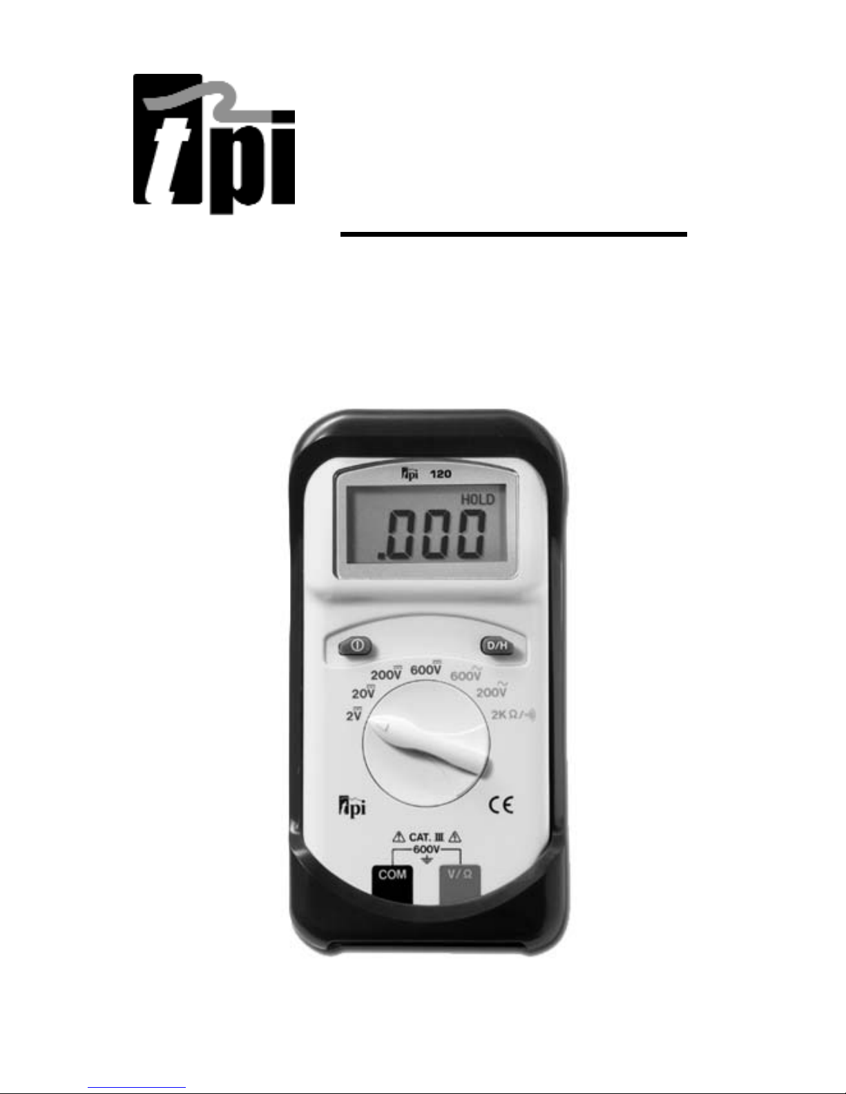
This is to certify that model 120 conforms to the
protection requirements of the council directive
89/336/EEC, in the approximation of laws of the
member states relating to Electromagnetic compati-
bility and 73/23/EEC, The Low Voltage Directive by
application of the following standards:
EN 50081-1 1992 Emissions Standard
EN 50082-1 1992 Immunity Standard
EN61010-1 1993 Safety Standard
EN61010-2-031 1995 Safety Standard
To ensure conformity with these standards, this
instrument must be operated in accordance with the
instructions and specifications given in this manual.
CAUTION:
Even though this instrument complies with the immunity stan-
dards, the accuracy can be affected by strong radio
emissions not covered in the above standards. Sources such
as hand held radio transceivers, radio and TV transmitters,
vehicle radios and cellular phones generate electromagnetic
radiation that could be induced into the test leads of this
instrument. Care should be taken to avoid such situations or
alternatively, check to make sure that the instrument is not
being influenced by these emissions.
SAFETY CONSIDERATIONS
WARNING: Please follow manufacturers
test procedures whenever possible. Do not
attempt to measure unknown voltages or
components until a complete understanding
of the circuit is obtained.
GENERAL GUIDELINES
ALWAYS
• Test the 120 before using it to make sure it is operating
properly.
• Inspect test leads before using to make sure there are no
breaks or shorts.
• Double check all connections before testing.
• Have someone check on you periodically if working alone.
• Have a complete understanding of circuit being measured.
• Disconnect power to circuit, then connect test leads to the
120, then to circuit being measured.
NEVER
• Attempt to measure unknown high voltages.
• Attempt to measure current with the meter in parallel to the
circuit.
• Connect the test leads to a live circuit before setting up the
instrument.
• Touch any exposed metal part of the test lead assembly.