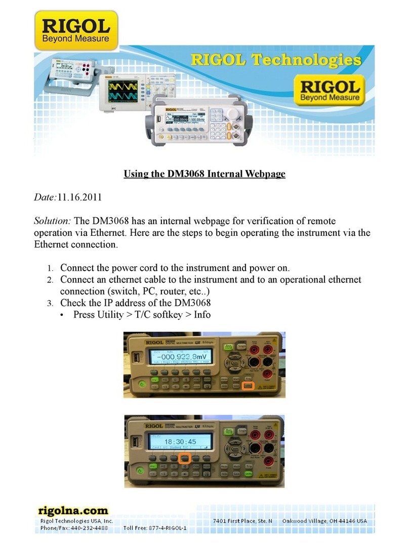
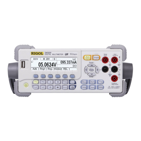
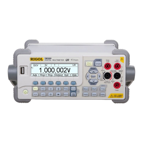
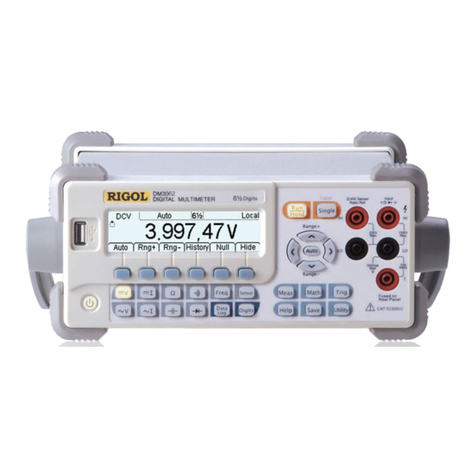
Rigol DM3068 User manual

RIGOL
Service Guide
DM3068 Digital Multimeter
Feb. 2014
RIGOL Technologies, Inc.


RIGOL
Service Guide for DM3068
I
Guaranty and Declaration
Copyright
© 2010 RIGOL Technologies, Inc. All Rights Reserved.
Trademark Information
RIGOL is a registered trademark of RIGOL Technologies, Inc.
Publication Number
SGC06101-1110
Notices
RIGOL products are protected by patent law in and outside of P.R.C.
RIGOL reserves the right to modify or change parts of or all the specifications
and pricing policies at company’s sole decision.
Information in this publication replaces all previously corresponding material.
RIGOL shall not be liable for losses caused by either incidental or consequential
in connection with the furnishing, use or performance of this manual as well as
any information contained.
Any part of this document is forbidden to be copied or photocopied or
rearranged without the express written approval of RIGOL.
Product Certification
RIGOL guarantees this product conforms to the national and industrial standards in
China as well as the ISO9001:2008 standard and the ISO14001:2004 standard.
Other international standard conformance certification is in progress.
Contact Us
If you have any problem or requirement when using our products or this manual,
please contact RIGOL.
E-mail: service@rigol.com
Websites: www.rigol.com

RIGOL
Service Guide for DM3068
II
Safety Requirement
General Safety Summary
Please review the following safety precautions carefully before putting the
instrument into operation so as to avoid any personal injuries or damages to the
instrument and any product connected to it. To prevent potential hazards, please use
the instrument only specified by this manual.
Use Proper Power Cord.
Only the power cord designed for the instrument and authorized by local country
could be used.
Ground The Instrument.
The instrument is grounded through the Protective Earth lead of the power cord. To
avoid electric shock, it is essential to connect the earth terminal of power cord to the
Protective Earth terminal before any inputs or outputs.
Observe All Terminal Ratings.
To avoid fire or shock hazard, observe all ratings and markers on the instrument and
check your manual for more information about ratings before connecting.
Use Proper Overvoltage Protection.
Make sure that no overvoltage (such as that caused by a thunderstorm) can reach
the product, or else the operator might expose to danger of electrical shock.
Do Not Operate Without Covers.
Do not operate the instrument with covers or panels removed.
Use Proper Fuse.
Please use the specified fuses.
Avoid Circuit or Wire Exposure.
Do not touch exposed junctions and components when the unit is powered.
Do Not Operate With Suspected Failures.
If you suspect damage occurs to the instrument, have it inspected by qualified
service personnel before further operations. Any maintenance, adjustment or
replacement especially to circuits or accessories must be performed by RIGOL
authorized personnel.
Keep Well Ventilation.
Inadequate ventilation may cause increasing of temperature or damages to the
device. So please keep well ventilated and inspect the intake and fan regularly.

RIGOL
Service Guide for DM3068
III
Do Not Operate in Wet Conditions.
In order to avoid short circuiting to the interior of the device or electric shock, please
do not operate in a humid environment.
Do Not Operate in an Explosive Atmosphere.
In order to avoid damages to the device or personal injuries, it is important to
operate the device away from an explosive atmosphere.
Keep Product Surfaces Clean and Dry.
To avoid the influence of dust and/or moisture in air, please keep the surface of
device clean and dry.
Electrostatic Prevention.
Operate in an electrostatic discharge protective area environment to avoid damages
induced by static discharges. Always ground both the internal and external
conductors of the cable to release static before connecting.
Handling Safety
Please handle with care during transportation to avoid damages to keys, knob and,
interfaces as well as other parts on the panels.
The disturbance tests of all models conform to the P/F values of A based
on the standard of EN 61326: 1997+A1+A2+A3 instead of P/F values of
B.
Input Terminal Protection Limit
The protection limit is defined for the input terminal:
1.Main input (HI and LO) terminals
HI and LO terminals are used for Voltage, Resistance, Capacitance, Continuity,
Frequency and Diodes measurements and should be used under the following
two conditions:
1) HI-LO protection: at most 1000 VDC or 750 VAC, this is also the maximum
measurable voltage. The limit can be expressed as 1000 Vpk.
2) LO-ground protection: floating at 500 Vpk (relative) with safety.
Since the HI terminal holds a maximum protection of 1000 Vpk relative to the
ground, the sum of the “float” and measured voltages cannot exceed 1000 Vpk.
2.Sampling (HI Sense and LO Sense/200 mA) terminals
HI Sense and LO Sense/200 mA terminals are used for 4-wire resistance
measurement and should be used under two conditions:
1) HI Sense-LO Sense/200 mA protection limit: 200 Vpk.
2) LO Sense/200 mA-LO protection limits: 0.5 Vpk. The current input fuse

RIGOL
Service Guide for DM3068
IV
on the rear panel provides the current passing through LO Sense/200
mA up to 500 mA protection.
3.Current input (10 A and Sense/200 mA) terminals
10 A and LO terminals are used for current measurements of 2 A and 10 A. The
maximum current going through the 10 A terminal is limited to 10 A by the
internal fuse. LO Sense/200 mA and LO terminals are used for current
measurements ranging from 200 µA to 200 mA. The maximum current going
through the LO Sense/200 mA terminal is limited to 500 mA by the internal
fuse.
NOTE:
In order to prevent the fuse from blowing out and protect the
multimeter, please use the current input terminals according to the
following requirements:
1) Do not connect the 10 A and LO Sense/200 mA input terminals into the
current measuring circuit at the same time.
2) Only use 10 A and LO terminals for measurements when the measured
current AC+DC RMS value goes within 200 mA and 10 A.
3) Select a proper current input terminal according to the estimated current
magnitude before connecting the multimeter to AC supplies if you want to
use current measurement.
4) The current into the 10 A terminal cannot exceed 13.5 A, otherwise it will
blow out the internal fuse; while the current into the LO Sense/200 mA
terminal cannot exceed 650 mA, otherwise the current input fuse from the
rear panel may be blown out.
IEC II Overvoltage Protection
In order to prevent electric shock, DM3068 provides overvoltage protection for
line-voltage mains connections meeting both of the following conditions:
1.The HI and LO input terminals are connected to the mains under Measurement
Category II conditions defined below.
2.The mains are limited to a maximum line voltage of 300 VAC.
WARNING: IEC II includes electrical devices connected to mains through an outlet
from the branch circuit. Such devices include most small appliances, test equipments
and other devices inserted into a branch socket.
DM3068 may be used to make measurements with the HI and LO inputs connected
to mains in such devices (up to 300 VAC), or to the branch socket. , the HI and LO
inputs of DM3068 cannot be connected to mains of permanently installed electrical
devices such as a main circuit-breaker panel, sub-panel disconnected box or wired
motors. Such devices and circuits are readily to beyond the protection of DM3068.
NOTE: Voltages above 300 VAC may be measured only in circuits that are isolated

RIGOL
Service Guide for DM3068
V
from mains. However, a transient overvoltage is also present in such circuits.
DM3068 was designed to safely withstand occasional transient overvoltage up to
2500 Vpk. Do not use this device to measure circuits whose transient overvoltage
may exceed this level.

RIGOL
Service Guide for DM3068
VI
Safety Terms and Symbols
Terms in this Manual. These terms may appear in this manual:
WARNING
Warning statements indicate the conditions or practices that could result in
injury or loss of life.
CAUTION
Caution statements indicate the conditions or practices that could result in
damage to this product or other property.
CAT I(1000V)
IEC Measurement Category I. The maximum voltage can be measured by
HI-LO terminal is 1000Vpk.
CAT II(300V)
IEC Measurement Category II. Inputs may be connected to mains (up to
300VAC) in the case of overvoltage in Category II.
Terms on the Product. These terms may appear on the product:
DANGER indicates an injury or hazard may immediately happen.
WARNING indicates an injury or hazard may be accessible potentially.
CAUTION indicates a potential damage to the instrument or other property might
occur.
Symbols on the Product. These symbols may appear on the product:
Hazardous
Voltage
Safety
Warning
Protective
Earth
Terminal
Chassis
Ground
Test
Ground

RIGOL
Service Guide for DM3068
VII
General Care and Cleaning
General Care:
Do not store or leave the instrument at a place where the instrument will be exposed
to direct sunlight for long periods of time.
Cleaning:
Clean the instrument regularly according to its operating conditions. To clean the
exterior surface, perform the following steps:
1. Disconnect the instrument from all power sources.
2. Moisten a cloth slightly (using a mild detergent or water) and clean the loose
dust on the outside of the instrument. Always take care when you clean the LCD
in order to avoid scuffing it.
CAUTION
To avoid damages to the instrument, do not expose them to corrosive
liquids.
WARNING
To avoid injury resulting from short circuit, make sure the instrument is
completely dry before reconnecting into a power source.

RIGOL
Service Guide for DM3068
VIII
Environmental Considerations
The following symbol indicates that this product complies with the applicable
European Union requirements according to Directives 2002/96/EC on waste electrical
and electronic equipment (WEEE) and batteries.
Product End-of-Life Handling
The equipment may contain substances that could be harmful to the environment or
human health. In order to avoid release of such substances into the environment and
harmful to human health, we encourage you to recycle this product in an appropriate
system that will ensure that most of the materials are reused or recycled
appropriately. Please contact your local authorities for disposal or recycling
information.

RIGOL
Service Guide for DM3068
IX
Document Overview
Chapter 1 Specifications
This chapter lists specifications and characteristics.
Chapter 2 Performance Test
This chapter introduces how to test the performance of DM3068 so as to know its
state well.
Chapter 3 Calibration
This chapter provides information about the calibration of DM3068.
Chapter 4 Disassembly & Assembly
This chapter guides you to disassemble and assemble DM3068 to reach a clearer
understanding of its structure.
Chapter 5 Troubleshooting & Maintenance
This chapter guides you to eliminate possible errors caused during the measurement
and contains information about routine maintenance.

RIGOL
Service Guide for DM3068
X
Table of Contents
Guaranty and Declaration ........................................................................ I
Safety Requirement ................................................................................. II
General Safety Summary.......................................................................... II
Safety Terms and Symbols........................................................................VI
General Care and Cleaning...................................................................... VII
Environmental Considerations ................................................................VIII
Document Overview.................................................................................IX
Chapter 1 Specifications.................................................................... 1-1
1. 1 DC Characteristics........................................................................1-1
1. 2 AC Characteristics........................................................................1-5
1. 3 Frequency and Period Characteristics.............................................1-9
1. 4 Capacitance Characteristics......................................................... 1-11
1. 5 Temperature Characteristics........................................................ 1-12
1. 6 Measurement Rate.....................................................................1-14
1. 7 Other Measurement Characteristics.............................................. 1-15
1. 8 General Specifications ................................................................1-16
Chapter 2 Performance Test .............................................................. 2-1
2. 1 Test Type ....................................................................................2-1
2.1.1 Self-Test.................................................................................2-1
2.1.2 Fast Test................................................................................2-3
2.1.3 Routine Test...........................................................................2-4
2. 2 Testing Equipments......................................................................2-5
2. 3 Test Conditions............................................................................2-6
2. 4 Input Connections........................................................................2-7
2. 5 Routine Test................................................................................2-8
2.5.1 Zero-offset Test ......................................................................2-8
2.5.2 Gain Test.............................................................................. 2-10
Chapter 3 Calibration......................................................................... 3-1
3. 1 Calibration Interval.......................................................................3-1
3. 2 Calibration Notice.........................................................................3-1
3. 3 To Obtain Calibration Service.........................................................3-1
Chapter 4 Disassembly & Assembly ................................................... 4-1
4. 1 Disassembly and Assembly Notices................................................4-1
4. 2 The 3D View of DM3068...............................................................4-2
4. 3 To Disassemble and Assemble Handle............................................4-3
4. 4 To Disassemble and Assemble Rear Panel.......................................4-4
4. 5 To Disassemble and Assemble Metallic Shell ...................................4-5
4. 6 To Disassemble and Assemble Fuse Seat........................................4-6
4. 7 To Disassemble and Assemble GPIB PCB ........................................4-7

RIGOL
Service Guide for DM3068
XI
4. 8 To Disassemble and Assemble Filter Board & Transformer................ 4-8
4. 9 To Disassemble and Assemble Front Panel & LCD ........................... 4-9
4. 10 To Disassemble and Assemble the Fan.......................................4-10
4. 11 To Disassemble and Assemble Mainboard ..................................4-11
4. 12 To Disassemble and Assemble Keypad PCB ................................4-12
Chapter 5 Troubleshooting & Maintenance.........................................5-1
5.1 Troubleshooting............................................................................... 5-1
5.2 Maintenance and Cleaning................................................................ 5-4
5.2.1 System Maintenance............................................................... 5-4
5.2.2 Principles of Circuit................................................................. 5-4
5.2.3 Components Inspection........................................................... 5-6
5.2.4 Replaceable Part list...............................................................5-10
5.2.5 Warranty ..............................................................................5-12


Chapter 1 Specifications RIGOL
Service Guide for DM3068
1-1
Chapter 1 Specifications
1. 1 DC Characteristics
Accuracy Specifications: ±(% of reading + % of range)[1]
Function Range[2] Test Current or
Burden Voltage 24 Hour[3]
TCAL
℃
±1
℃
90 Day
TCAL
℃
±5
℃
1 Year
TCAL
℃
±5
℃
Temperature
Coefficient
0
℃
to (TCAL
℃
-5
℃
)
(T
CAL℃
+5
℃
) to 50
℃
DC Voltage
200.0000mV
0.0020+ 0.0020
0.0030 + 0.0025
0.0040 + 0.0025
0.0005 + 0.0005
2.000000V
0.0015 + 0.0005
0.0020 + 0.0006
0.0035 + 0.0006
0.0005 + 0.0001
20.00000V
0.0020 + 0.0004
0.0030 + 0.0005
0.0040 + 0.0005
0.0005 + 0.0001
200.0000V
0.0020 + 0.0006
0.0040 + 0.0006
0.0050 + 0.0006
0.0005 + 0.0001
1000.000V[4]
0.0020 + 0.0006
0.0040 + 0.0010
0.0055 + 0.0010
0.0005 + 0.0001
DC Current
200.0000uA
<0.03V
0.010 + 0.012
0.040 + 0.015
0.050 + 0.015
0.0020 + 0.0030
2.000000mA
<0.25V
0.007 + 0.003
0.030 + 0.003
0.050 + 0.003
0.0020 + 0.0005
20.00000mA <0.07V 0.007 + 0.012 0.030 + 0.015 0.050 + 0.015 0.0020 + 0.0020
200.0000mA
<0.7V
0.010 + 0.002
0.030 + 0.003
0.050 + 0.003
0.0020 + 0.0005
2.000000A
<0.12V
0.050 + 0.020
0.080 + 0.020
0.100 + 0.020
0.0050 + 0.0010
10.00000A[5]
<0.6V
0.100 + 0.010
0.120 + 0.010
0.150 + 0.010
0.0050 + 0.0020
Resistance[6]
200.0000Ω
1mA
0.0030 + 0.0030
0.008 + 0.004
0.010 + 0.004
0.0006 + 0.0005
2.000000kΩ
1mA
0.0020 + 0.0005
0.008 + 0.001
0.010 + 0.001
0.0006 + 0.0001
20.00000kΩ
100uA
0.0020 + 0.0005
0.008 + 0.001
0.010 + 0.001
0.0006 + 0.0001
200.0000kΩ
10uA
0.0020 + 0.0005
0.008 + 0.001
0.010 + 0.001
0.0006 + 0.0001
1.000000MΩ
2uA
0.002 + 0.001
0.010 + 0.001
0.012 + 0.001
0.0010 + 0.0002
10.00000MΩ
200nA
0.015 + 0.001
0.030 + 0.001
0.040 + 0.001
0.0030 + 0.0004
100.0000MΩ
200nA || 10MΩ
0.300 + 0.010
0.800 + 0.010
0.800 + 0.010
0.1500 + 0.0002
Diode Test
2.0000V[7]
1mA
0.002 + 0.010
0.008 + 0.020
0.010 + 0.020
0.0010 + 0.0020

RIGOL Chapter 1 Specifications
Service Guide for DM3068
1-2
Continuity Test
2000.0Ω
1mA
0.002 + 0.010
0.008 + 0.020
0.010 + 0.020
0.0010 + 0.0020
[1] Specifications are for 90-minute warm-up and 100NPLC integration time. For integration time <100NPLC, add the appropriate “
RMS Noise Adder
”
listed in the following table.
[2]
10% overrange on all ranges except DCV 1000V and DCI 10A range.
[3]
Relative to calibration standards.
[4]
For each additional volt over ± 500 V, add 0.03mV error.
[5]
For continuous current > 7A DC or 7A AC RMS, 30 seconds ON and 30 seconds OFF.
[6]
Specifications are for 4–wire resistance measurement or 2–wire resistance measurement using REL operation. Without REL operation, add 0.2 Ω
additional errors in 2-wire resistance measurement.
[7]
Accuracy specifications for the voltage measured at the input terminal only. 1 mA test current is typical. Variation in the current source will create
some variation in the voltage drop across a diode junction.
Performance Versus Integration Time – 50Hz (60Hz) Power-line Frequency
Integration
Time
Number of
Power line
Cycles
(NPLC)
Resolution[1]
(ppm Range) NMRR[2]
(dB)
Readings/s[3] RMS Noise Adder[4] (% of Range)
50Hz 60Hz DCV 20V
DCV 2V
200V
Resistance 2kΩ
20kΩ
DCV 1000V
DCI 2mA
200mA
DCV 200mV
Resistance 200Ω
DCI 10A
0.006
2.7
0
10000
10000
0.0006
0.0007
0.0015
0.0040
0.02
1.6
0
2500
3000
0.0004
0.0004
0.0008
0.0025
0.06
1
0
833
1000
0.0003
0.0003
0.0006
0.0025
0.2
0.5
0
250
300
0.0001
0.0002
0.0003
0.0015
1
0.22
60
50
60
0
0.0001
0.0002
0.0004
2
0.17
60
25
30
0
0
0.0001
0.0003
10
0.08
60
5
6
0
0
0
0.0002
100
0.035
60
0.5
0.6
0
0
0
0
[1]
Typical value. Resolution is defined as the typical 20V range RMS noise (using auto zero “Once”).
[2]
Normal mode rejection ratio for power-line frequency ±0.1%. For power-line frequency ±1%, subtract 20dB. For ±3%, subtract 30dB.
[3]
Maximum rate for DCV, DCI, 2-wire resistance and 4-wire resistance functions.

Chapter 1 Specifications RIGOL
Service Guide for DM3068
1-3
[4]
The basic DC accuracy specifications include RMS noise at 100 NPLC. For <100 NPLC, add “
RMS Noise Adder
” to the basic DC accuracy
specifications.
SFDR & SINAD[1]
Function
Range
Spurious-Free Dynamic Range (SFDR)
Signal-to-Noise-and-Distortion (SINAD)
DCV
200mV
81
76
2V
79
78
20V
79
75
200V
83
80
1000V
86
82
DCI
200uA
89
69
2mA
86
81
20mA
88
69
200mA
81
79
2A
69
64
[1]
Typical value. -1dBFS, 1kHz single tone. 100us aperture time, zero trigger delay, auto zero off and 4096 samples.
Measuring Characteristics
DC Voltage
Input Resistance
200mV, 2V, 20V ranges: Selectable 10MΩ or >10GΩ
(For these ranges, input beyond ±26V are clamped through 106kΩ (typical) )
200V and 1000V ranges: 10MΩ±1%
Input Protection
1000V
Input Offset Current
50pA, at 25
℃
, typical
CMRR (common mode
rejection ratio)
140dB for 1 kΩ unbalance in LO lead, ±500VDC peak maximum.
Resistance
Measurement Method
Selectable 4-wire or 2-wire resistance
Current source referenced to LO input
Open-circuit Voltage
Limited to <10V
Max. Lead Resistance
(4-wire)
10% of range per lead for 200 Ω, 2 kΩ ranges, 1 kΩ per lead on all other ranges

RIGOL Chapter 1 Specifications
Service Guide for DM3068
1-4
Input Protection
1000V on all ranges
Offset Compensation
Available on 200Ω, 2kΩ and 20 kΩ ranges.
DC Current
Shunt Resistor
100Ω for 200uA, 2mA
1Ω for 20mA , 200mA
0.01Ω for 2A, 10A
Input Protection
Externally accessible 500mA, 250V fast blow fuse at the rear panel for 200uA, 2mA, 20mA and 200mA ranges.
Internal 10A, 250 V slow blow fuse for 2A and 10A ranges.
Continuity/Diode Test
Response Time
300 samples/sec, with audible tone
Continuity Threshold
Adjustable from 1 Ω to 2000 Ω
Autozero OFF Operation (typical value)
Following instrument warm-up at the environment temperature ±1
℃
and <5 minutes, add 0.0001 % range + 2 uV for DCV and 2 mΩfor resistance.
Settling Time Considerations
Reading settling times are affected by source impedance, cable dielectric characteristics and input signal changes. The default measurement delay is selected
to give first reading right for most measurements.
Measurement Considerations
Telon or other high-impedance, low-dielectric absorption wire insulation is recommended for these measurements.

Chapter 1 Specifications RIGOL
Service Guide for DM3068
1-5
1. 2 AC Characteristics
Accuracy Specifications: ±(% of reading + % of range)[1]
Function
Range[2]
Frequency Range
24 Hour[3]
TCAL
℃
±1
℃
90 Day
TCAL
℃
±5
℃
1 Year
TCAL
℃
±5
℃
Temperature
Coefficient
0
℃
to (TCAL
℃
-5
℃
)
(TCAL℃+5℃) to 50℃
True RMS AC
Voltage [4]
200.0000mV
3Hz- 5Hz
1.00 + 0.03
1.00 + 0.04
1.00 + 0.04
0.100 + 0.004
5Hz-10Hz
0.35 + 0.03
0.35 + 0.04
0.35 + 0.04
0.035 + 0.004
10Hz-20kHz
0.04 + 0.03
0.05 + 0.04
0.06 + 0.04
0.005 + 0.004
20kHz-50kHz
0.10 + 0.05
0.11 + 0.05
0.12 + 0.05
0.011 + 0.005
50kHz-100kHz
0.55 + 0.08
0.60 + 0.08
0.60 + 0.08
0.060 + 0.008
100kHz- 300kHz
4.00 + 0.50
4.00 + 0.50
4.00 + 0.50
0.20 + 0.02
2.000000V
3Hz-5Hz
1.00 + 0.02
1.00 + 0.03
1.00 + 0.03
0.100 + 0.003
5Hz-10Hz
0.35 + 0.02
0.35 + 0.03
0.35 + 0.03
0.035 + 0.003
10Hz-20kHz
0.04 + 0.02
0.05 + 0.03
0.06 + 0.03
0.005 + 0.003
20kHz-50kHz
0.10 + 0.04
0.11 + 0.05
0.12 + 0.05
0.011 + 0.005
50kHz-100kHz
0.55 + 0.08
0.60 + 0.08
0.60 + 0.08
0.060 + 0.008
100kHz - 300kHz
4.00 + 0.50
4.00 + 0.50
4.00 + 0.50
0.20 + 0.02
20.00000V
3Hz-5Hz
1.00 + 0.03
1.00 + 0.04
1.00 + 0.04
0.100 + 0.004
5Hz-10Hz
0.35 + 0.03
0.35 + 0.04
0.35 + 0.04
0.035 + 0.004
10Hz-20kHz
0.04 + 0.04
0.07 + 0.04
0.08 + 0.04
0.008 + 0.004
20kHz- 50kHz
0.10 + 0.05
0.12 + 0.05
0.15 + 0.05
0.012 + 0.005
50kHz-100kHz
0.55 + 0.08
0.60 + 0.08
0.60 + 0.08
0.060 + 0.008
100kHz-300kHz
4.00 + 0.50
4.00 + 0.50
4.00 + 0.50
0.20 + 0.02
200.0000V
3Hz-5Hz
1.00 + 0.02
1.00 + 0.03
1.00 + 0.03
0.100 + 0.003
5Hz-10Hz
0.35 + 0.02
0.35 + 0.03
0.35 + 0.03
0.035 + 0.003
10Hz-20kHz
0.04 + 0.02
0.07 + 0.03
0.08 + 0.03
0.008 + 0.003
20kHz-50kHz
0.10 + 0.04
0.12 + 0.05
0.15 + 0.05
0.012 + 0.005

RIGOL Chapter 1 Specifications
Service Guide for DM3068
1-6
50kHz-100kHz
0.55 + 0.08
0.60 + 0.08
0.60 + 0.08
0.060 + 0.008
100kHz-300kHz
4.0 + 0.50
4.0 + 0.50
4.0 + 0.50
0.20 + 0.02
750.000V[5]
3Hz-5Hz
1.00 + 0.02
1.00 + 0.03
1.00 + 0.03
0.100 + 0.003
5Hz-10Hz
0.35 + 0.02
0.35 + 0.03
0.35 + 0.03
0.035 + 0.003
10Hz-20kHz
0.04 + 0.02
0.07 + 0.03
0.08 + 0.03
0.008 + 0.003
20kHz-50kHz
0.10 + 0.04
0.12 + 0.05
0.15 + 0.05
0.012 + 0.005
50kHz-100kHz
0.55 + 0.08
0.60 + 0.08
0.60 + 0.08
0.060 + 0.008
100kHz-300kHz
4.0 + 0.50
4.0 + 0.50
4.0 + 0.50
0.20 + 0.02
True RMS AC
Current[8]
200.0000uA
3Hz-5Hz
1.10 + 0.06
1.10 + 0.06
1.10 + 0.06
0.200 + 0.006
5Hz-10Hz
0.35 + 0.06
0.35 + 0.06
0.35 + 0.06
0.100 + 0.006
10Hz-5kHz
0.15 + 0.06
0.15 + 0.06
0.15 + 0.06
0.015 + 0.006
5kHz-10kHz
0.35 + 0.70
0.35 + 0.70
0.35 + 0.70
0.030 + 0.006
2.000000mA
3Hz-5Hz
1.00 + 0.04
1.00 + 0.04
1.00 + 0.04
0.100 + 0.006
5Hz-10Hz
0.30 + 0.04
0.30 + 0.04
0.30 + 0.04
0.035 + 0.006
10Hz-5kHz
0.12 + 0.04
0.12 + 0.04
0.12 + 0.04
0.015 + 0.006
5kHz-10kHz
0.20 + 0.25
0.20 + 0.25
0.20 + 0.25
0.030 + 0.006
20.00000mA
3Hz-5Hz
1.10 + 0.06
1.10 + 0.06
1.10 + 0.06
0.200 + 0.006
5Hz-10Hz
0.35 + 0.06
0.35 + 0.06
0.35 + 0.06
0.100 + 0.006
10Hz-5kHz
0.15 + 0.06
0.15 + 0.06
0.15+ 0.06
0.015 + 0.006
5kHz-10kHz
0.35 + 0.70
0.35 + 0.70
0.35 + 0.70
0.030 + 0.006
200.0000mA
3Hz-5Hz
1.00 + 0.04
1.00 + 0.04
1.00 + 0.04
0.100 + 0.006
5Hz-10Hz
0.30 + 0.04
0.30 + 0.04
0.30 + 0.04
0.035 + 0.006
10Hz-5kHz
0.10 + 0.04
0.10 + 0.04
0.10 + 0.04
0.015 + 0.006
5kHz-10kHz
0.20 + 0.25
0.20 + 0.25
0.20 + 0.25
0.030 + 0.006
2.000000A
3Hz-5Hz
1.10 + 0.06
1.10 + 0.06
1.10 + 0.06
0.100 + 0.006
5Hz-10Hz
0.35 + 0.06
0.35 + 0.06
0.35 + 0.06
0.035 + 0.006
10Hz-5kHz
0.15 + 0.06
0.15 + 0.06
0.15 + 0.06
0.015 + 0.006
5kHz-10kHz
0.35 + 0.70
0.35 + 0.70
0.35 + 0.70
0.030 + 0.006
10.00000A[6]
3Hz-5Hz
1.10 + 0.08
1.10 + 0.10
1.10 + 0.10
0.100 + 0.008
Other manuals for DM3068
5
Table of contents
Other Rigol Multimeter manuals
Rigol
Rigol DM3061 User manual
Rigol
Rigol DM3058 Use and care manual

Rigol
Rigol DM3058 Operating instructions
Rigol
Rigol DM3068 User manual
Rigol
Rigol DM3063 User manual

Rigol
Rigol DM3000 Series User manual
Rigol
Rigol DM3068-OB User manual
Rigol
Rigol DM3000 Series Operating instructions
Rigol
Rigol DM3058 Operating instructions
Rigol
Rigol DM3061 User manual
