National HRO User manual

UDSVRWGVRON MaDWaL
for
TEE
Designed to meet
the
most ex-
acting demands of the more
advanced communication service
Price
10c

Whileintendedprimarily as an operating
instruction manual, it is hoped that this
booklet will also serve to better acquaint
the owner of a National HRO high-fre-
quency communication receiver with the
engineering details of its design. Only by
a proper appreciationof some ofthe many
unusual design features of this new re-
ceiver
is
it possible for the operator to
secure the unusually high degree of per-
formance that we have built into the HRO.
We express indebtednessto the American
Radio Relay League for permissionto re-
print, in part, articles published in past
issues of their official organ,
QST.
NATIONAL
COMPANY,
INC.
Malden, Mass.,
U.
S.
A.
Copyright
1939

The
HRO
Amateur Communications Receiver
T
HEHRO receiver is a high-frequency super-
heterodyne employing nine tubes,
as
fallows:
6eeondR.F
..............................
5s
or6D6
First
Deteotor.
...........................
.57
or
6C6
High
Frequency
OsciUator
.................
.57
or
6C6
First1.F
..................................
58
or6D6
Seoond1.F
................................
58
oieD6
Diode Detector,
AYC,
First Audio.
.........
.2B7
or
6B7
SeoondAudio
.............................2A5or42
Beat
Frequency
Osoilistor.
................
.57
or
6C6
Unless otherwise specified, all models are
equipped with 6.3-volt tubes, for either A.C. or
battery operation.The2%-volt tubes ean be used
if
desired,sincethetwotypesareinterchangeable,
but the6.3-volt tubes
are
to
be preferred.
For A.C. operation, the receiver
is
adjusted to
give best performance with
the
National type
697 AB power unit, which delivers 230 volts at
75 milliamperas, ~nd6.3 volts at3.1amperes.
The battery model, type HRO-B, is djusted
for maximumperformancewith a plate potential
of 180volts at a current drain of approximately
55 milliamperes. Normal operation from A.C.
lines with the
HRO-B
can be secured by the em-
ployment of a National type No. 5886 power
pack, a unit which, under load, delivers approx-
imately 170 volts D.C. at 50 milliamperes and
.
6.3 volts A.C. at3.1 amperes.
All
voltage dividers, bias requirements, etc.
are built into the receiver.
Other power units may be used provided they
will fulfil these specifications closely, but it is im-
portant that an adequate heater supply be fur-
nished to compensatefor the voltage drop in the
heater leads
of
the power supply crthle.
The HRO receiver
has
been designed around
and tested
with
RCA or Sylvania tubes; conse-
quently, we can vouch for its performance only
when these tubes are used.
Antenna
The input circuit of the HRO is arranged for
operation with either the doublet type or the
single-wire type of antenna. There are two input
binding posts, marked "ANT" and "GND."
When using a single-wire sntenna, the lead-in
shouldbe connected
to
the antenna post and the
short flexible lead, which is connected
to
the
chassis near the ground post, should be clamped
under the "GND" terminal. An externalground
connection mav
or
mav not be neoessarv. deoend-
,.
.
Lng
iupcm
rht ~r~if~ll~rt~~:~.
TL
ground
id
uiuaUy
rlcsi~.ablesvilett receiviug \r.avcle:.grlu ab~vz
100
n,cte<>,hut ior
STAY
,iragtl.r bcl>.v
80
lueter~,rhv
use of a ground may actually weaken signals.
Doublet antenna feeders should be connected
directly
to
the input terminals and the flexible
ground connection, mentioned above,
is
not used
atall.
TheInput impedanceof thereceivervaries over
the total frequencyrange but averagesabout 500
ohms.
Output
Circuit
T1.e plarc circuit
oi
the cutl,ut rubc is broughr
ro the cutl~ut
t~p
jack I>mted
~t
the
rehr
left-
I.:xl.rl -iJc. 'l'hcre is no
<,UlDUr
rr3nzformer
m
rhe
receiver.
Thespeaker requirementsarenot atallcritical,
5
but tone quality will, of course, depend almost
'
entirely upon speaker characteristics.
A
good
*
'-
magnetic speaker will be satisfactory,provided it
is capable of carrying the plate current of the
output tube (about 30 ma.). Many magnetic
speakerswill requirea filtersystem,however, and
such a
filter
may consist of a l-to-1 transformer,
or a 30-henry choke and a l-mfd. condenser.
Dynamic speakers are, in general, superior to
the magnetic types, but if these are used some
DravisiOn must be made for field excitation. since
this
power
ramor be oornincd eitller ilo~uthe re-
ccivcr or t1.c pon.sr unir.
K,r
rhi. reat"", rLe per-
manent rnsgner r).p20i
dyunmi;
apesker
i>
rerorn-
mended, no field excitation being requ~red.The
output impedanceof the HRO is 7000 ohms, and
a dynamic speakermust, of course, have a snita-
ble built-in coupling transformer of 7000-ohm
input impedance.
Aheadphonejack is located on the front panel,
just below and to the right of the "S"-meter.
This jack
is
wired into the output of the pentode
section of the 6B7. When the phones are plugged
in,
thesignalinput to the la$t tube is completely
disconnected.Itis important, however, that the
plate circuit of the output tube be completed at
all times.
If
the speaker is to be disconnected,
a
jumper must be inserted in the tip jacks to con-
nectthemtogether.
If
thisprecautionisneglected,
theoutput tubemay be seriouslyinjured.

THE HRO RECEIVER

THE HRO RECEIVER
5
Controlr
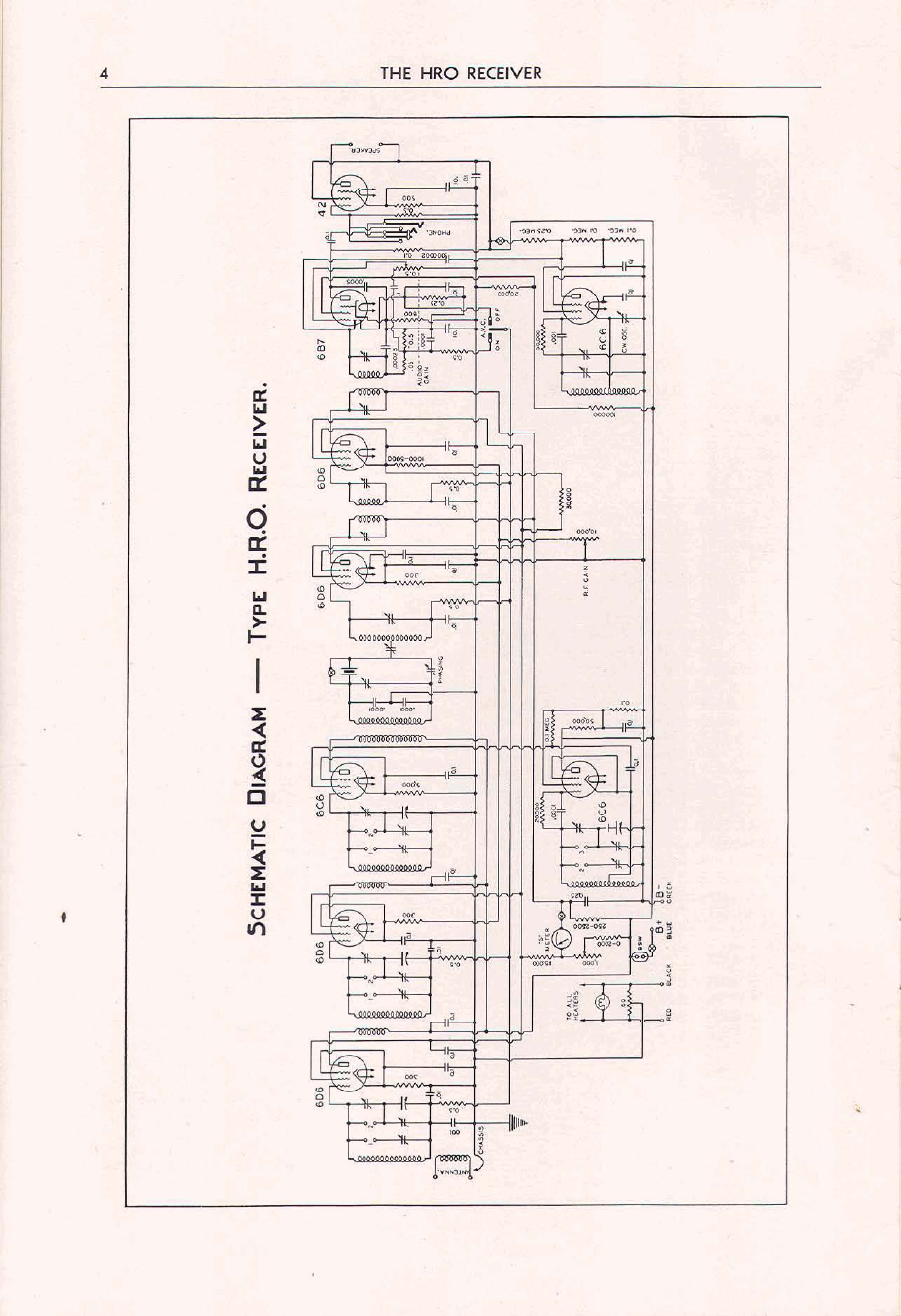
The main tuning dial is located near the eent,er
of thefront panel and operates the Cgang tuning
condenser.
Full
details of the tuning arrangement
aill be found in the last section of this booklet,
which is reprinted from
an
article originally ap
pearing in
QST.
Starting atthe top right-hand sideof the front
panel, the uppermost knob is the Variable Selec-
tivity Control of the Single-Signal Crystal Filter.
With the crystal filter inuse, minimum selectivity
ill
be found with the pointer nearly vertical.
Rotating the knob in either direction
from
this
point
niU
increase thcselectivity. When the filter
is not in use, the knob should be set atthe point
giving maximum volume and sensitivity.
Immediately below the Selectivity Control is
the Phasing Control and the Crystal Filter
Su-itch. When this control
is
rotated to
0,
the
crystal filter is disconnected. When the control is
atanyothersettingbetwee11
1
and
10,
itacts
as
n
phasing condenser for balancing the crystal
bridge circuit, eliminating heterodyne?, etc. The
action of these two controls is explained in detail
in
Part
2
of the Alignment Section.
The switch below the phasing control is
eon-
nected in the
B+
lead of the receiver and its pur-
pose is
to
shut
off
the receiver
during
periods
of
transmission OR WHEN CHANGING COILS.
This lartfunction is important. Sel.ies connected
ulth the
B+
switch and mounted atthe rear of
the chassis is
a.
pair of oontaots, BSW, intended
forusewith relay control of thereceiver.
The
hottom controlon theright-hand sideis an
R.F. Gaul Control, connected to the second R.F.
tubeand to thetwo I.F.
tubes.
At the bottom left-handside of the front panel
is
located the C.W. Oscillator Switchand Vernier
Tuning Control. Thec.~.oscillator isused to ob-
tain an audible beat note when ~zceiving
O.W.
signals
or
to locate the carrier of
weak
phone and
broadcast stations. After the phone carrier has
been found, the
o.~.
oscillator is, of course,
turned off.
The switch just above the c.w. beat oscillator
dial is far turning the AVC on
or
off.
AVC
ie
dis-
connected with the toggle thrown to the right.
Above this switch is the Audio Gain Control,
which is wired into the output of the diode de-
tector and
swves,
therefore, to control audio
volume xrhen using either headphones
or
speaker.
The S-meter for indicating carrier intensity of
signal strength is in the upper left-hand comer.
Just below it, and to the left, is
a
push-switch
which connects the meter in the circuit.
Operating Instructions
Phone
or
Broadcart Reception
In receiving phone signals, the AVC may
or
may not be used,
as
desired. If it is not used, we
sueeest
onerxt,inr
t,he
audio gain control about
halfway
on
and controlling the sensitivity with
the
R.F.
gain control. If the operator prefers a
"quiet" receiver, the audio control may be op-
erated at
1
or
2.
If
AVC is used (left-hand toggle
thrown to the left), the R.F. gain control may be
turned all the way on;i.e., to
10;
and the volume
controlled by the audio gain control only. The
setting of the turogain controls
is
largely a mat-
ter to be determined by the preference of the
operator and by receiving conditions. If, for in-
stance, local noise
01.
atmospheric static
is
high,
it aill be desirable to retard the R.F. gain con-
trol when using AVC
so
that the sensitivity of
the receiver will be held to
a
definite maximum.
1
If the
C.W.
oscillator is to be used for locating
carriers, as mentioned above, the AVC switch
must be intheoff position (to theright). Turning
on
the e.w. oscillator with the AVC an will block
the reccivei, making reception of anything but
.
extremely strongsignals impossible.
C.W.
Reception
When receiving c.w. signha, the c.w. oscillator
must be turned on and the AVC switch turned
off.Best signal-to-noise ratio will usually be ob-
tained by retarding the audio gain control
considerably and controlling sensitivity with the
R.F. gain control. Turning on the c.w. oscillator
switch will, of course, result in
a
considerable in-
crease in circuit noise. When the control is turned
back and forth, the characteristic pitch of this
noise will change. When the characteristic pitch
is fairly high, the semi-"single-signal" properties
of
the receiver are very pronounced, one side of
theaudio beat note beingseveral times
as
loud
tu;
the other.
Phone Reception Uring the Crystal Filter
The use of the crystal filter in phone reception
is recommended particularly when tho operator
must contend with heavy interference, static,
heterodynes, etc. Since such conditions prevail
at lnost times in the amateur phone bands, the
filter will be found particularly useful to amateur
phone operators. To receive
a
phone signal when
using the crystal filter,the fdter is switched in by
means of the phasing control and the phmhlg
dial set atapproximatsly mid-scalo. The selectiv-
ity control is then adjusted for minimum
selec-
tivity,
ar
indicated by maximum noise
as
the
control is rotated buck and forth. All phone sig-
nals will be greatly reduced in volume, making it
necessary to advance both audio and R.F. gain
rontrols. The signals may then be tuned in in
the usual manner, but it will
bc
found that the
selectivity is very high, with the result that all
audio frequency side bands above a few hundred
cycles are comparatively weak. Normally, thi?
nould result in low intelligibility of the received
signal, but since the background noise, static,
etc. hsve been oorrespondingly reduced, the net
result is usually animprovement.
The principal advantage of the crystal filter,

6
THE HRORECEIVER
however,
is
its ability to eliminate heterodynes.
Suppose,for instance,a signal hssbeen carefully
tuned in with reasonably good inteuigibility and
during the transmission an interfering station
comes on, causing a bad heterodyne, inverted
speech, etc., ordinarily the desired signal would
be "smeared," but careful adjustment of the
phasing condenser will eliminate the heterodyne
and the interfering station, in most oases, com-
pletely. Intelligibility will remain practically
ss
good
as
beforetheinterfering station came on.
From a practical standpoint, it is important
that the crystal filter be used most of the time
wheresuchinterferenceis aptto be encountered,
as
it
is almost impossibleto switch on thecrystal
filter and re-tune the desired signal through the
heterodyne. The phasing adjustment will remove
one signal only.
If
another interfering station
comes on, however, only one heterodyne will he
present, instead of the several resulting from
three station carriers beating together.
C.W.
Rece~ticnwith the Crystal Filtel
To use the crystal aterfor ow reception, the
flier
is
switched m by means of the phaslng
control and the
ha sing
condenser set about
mid-scale, The AVC switch must be off and the
c.w. oscillator turned on. Advancing the
R.F.
and audio gain controls mll result in a hollow,
ringing soundthepitch of which %dldependupon
the setting of the 0.w. oscillator dial. The actual
pitch is not important
as
long as
it
is
near the
middleof the audiorange, where thelondspefiker
or phones have good sensitivity.
When a signal
is
picked up, it
will
be found
that
as
the recaver
is
tuned slowly across the
carrier the beat note will be very sharply peaked
at the same pitch as that
of
the ringing noise,
previouslymentioned.
All
other parts of the beat
note will be extremely weak and, furthermore,
this peak will be foundto occur on only one side
of theaudio beat note. The sharpnessof thepeak
is
determined by the selectivity control (upper
righehand knob). At
maximum
selectivity, the
peak is so sharp that it may be hard to hd,
whereas at minimum selectivity thepeak will he
very broad. If a signal
is
being received, after
,
havlng been properly tuned in, and an inter-
feringstation comes on, theresulting heterodyne
and
interference
may be eliminated by adiust-
ment of the phasing condenser. Th~sphasing
adjustmentis effectivein elunmnatinginterference
regardlessof the setting of the selectivity control.
S-Meter
The &meter serves
to
indicate the strength of
a received signal. It
1s
calibrated from
1
to
9
in
arbitrary nnlts which correspond,roughly, to the
defilutionof the mne points of the
"S"
scale of
the R-8-T system of amateur signalreports.
Probably no two operators
mll
agritgree
on just
how strong a signal must be to warrant an
8-9
report. After making measurements on a large
number of amateur signals, the present meter
scalewas chosen and we believe
it
will
provide
a
good practical
invans
oi giving svumate repow.
The
avcomp3nying rurvr rl.ow the
rplation
bcmeen averhpa mctcr rcadinci aud the actual
signal input toreceiver in mi&volts snd from
this curve it
wdl
he noted that each
"SS"
unit
is
equal to a change of app~oxunatelg
4
db. The
40
db. range above the
8-9
level is used for com-
parative checks on extremely strong
s1gnal.s.
Figure
3
shows the "S-meter" network eon-
nec$ed in the
B
supply circuit
to
the
RF.
and
I.F.
stages. Actually themeter
is
themdicator of
a
bridge clcuit, three legs of which
are
6xed
resistors, and the fourth (variable) leg the plate
circuitsof the a.v.c. controlledtubes. The br~dge
is hallanced by means of the manual R.F. gain
control, which, through
its
action of indirectly
changing the plate resistance of the tubes, auto-
matically adjusts the
R.F.
and
IF.
gain
to
a
predeterm~nedlevel at the same time that the
meter
a
brought to zero. The strength of the
incomngsignal
is,
therefore,accurately indicated
by the acQonof the A
V.C.
circuitsin controlling
high frequencygain.
Before making a measurement on a
signal,
certain adlnstmente must he made. Since the
meter is actuated by the amount
of
signal
reach-
ing thesecond detector, itis obviously necesary
that the receiver he adjusted to have a prede-
termined amount of ampli6cation betrreen the
antenna and second detector.
To
adjust the
amplificaizon to the proper value, the
.4VC
switch must be off, the C.W.oscillator
off,
the
crystal filter off, and the selectivity control set
for maximum sensitivity. Now
press
the meter
switch and advance the R.F gain control untll
the meter comes to
0.
The
R
F. gain dial
will
read about
9%.
The receiver
is
now adjustedand

THE
HRO
RECEIVER
7
the strength of any
signal
may he measured by
,
tbrouing the
AVC
switch on and tuning for
maximum meter deflection. The audio
gain
con-
trol does not have any effect onthe RF. adjust-
ments or upon the meter reading,
so
that itmay
be
retarded
as
much as necesary to prevent
audio overload when making the preliminary
.
adjustments.
If
the signal being measured
is
extremely
strong, honxever, or
if
loeal noise is exceptionally
high, it may
be
impossible to bring themeter to
0.
In
this
case.
it is necessary to detune the
&ve~
from the
signal
or to dimnnect the
antenna. The above procedure will hold true
when eheeking either phone or
C.W.
stations.
It
is, however, impossible to obtain
a
continuous
check on c.w.
signals,
as
the beat oscillatormust
be
off.
If
it should happen that the Smeter network
getsout of balance, thealignmentprocedure is
as
follows.Disconnectthe antenna and turn offthe
AVC,
set
the R.F.
gain
wntml at
9%,
then, by
means of a serew driver, adjust the wntml
No.
17
(as
shown in the top
view)
until the
meter
reads
0.
This wntml is located in the
chasis
in
back of the meter near the antenna
bindingpost.
Coil
Ranges
Four plug.in coil assemblies are supplied as
standard equipment for the
HRO
receiver, each
assembly consistine of three R.F. wils and one
oscillator coil,
all
individually shielded and
provided with built-in trimmer condensers.
Calibration curves
are
mounted on the fmnt of
eachassemblv.
The four Aemblies cover all frequencies be-
tween
1.7
and
30
megacycles, the division being
as
follows:
1.7
to
4.0
mc
3.5
to
7.3
mc.
7
0
to
14.4
mc.
14.0
to
30
0
mc
Inspectionof the milterminalpanels
win
show
several small rectangular metal pieces. There
are
two of thesepiemsorterminal blocksoneach
of the coil pad.
A
small flat-head machine
screw
will
be found in the left-hand termmal
block of
each
mil, looking at the assembly from
the front. With the screws in the lefeband posi-
A
tion, the coil range will he that shown in theleft-
hand, orgeneralwverage, cbart.
If
itisdesiredto
change the calibration to smateur band-spread,
as
shown on the righehand chart,
it
isonlyneces-
sary
to move the four serews to the righehand
terminal block of esch mil.
A
complete description of the wils, tuning
condensers, and the rwechanging system, is
given in the lastsection of this booklet.
In addition to the coils furnished
as
standard
equipment, other assemblies are available, wv-
ering frequencies fmm
2.05
mcs. to
50
kc. and
rsre listed on the back cover of this manual.
Alignment and Service Data
T
HE four high-frequency coil &lies are
slirmed in the laborato~to the individual
receiver
with
which the" agto
be
used.
No wil
~~~
~-
~
"
~ ~ ~
~~
~~~~~~
~
~~
~
sdjusrments
of
any kind shouldbe ny
after
the receiver is put inu, operation, but
d
cokare
purebased separ~telythe &went should be
checked in aocordsncc with the following pro-
cedure.
The mil panel screws must be in the left-hand
terminal
blocks togive thefullcoverage range,
as
described in the preceding section. The tuning
dial is turned
to
aonrohtelv
490
and
a
fre-
.
.
quency meter, or
accurate
test
oscillator,
is set to
the frequency in&caied b.v the general wverage
calibrauon chart.
This
nffl,
moldentally, always
be near the high-frequency edgeof someamateur
band. The dtorcoil trimmer, shown on
the top view of the receiver
as
No.
8,
is then
adjusted so that the
dial
reading checks the cali-
bration curve. TrimmersNos.
Z,4
and
6
arethen
adjusted for
maximum
sensitivity. In adjusting
these three trimmers, no
signal
is nee-ry,
as
the correct adjustment is that wbich
mill
give
dumbackground cr tube noise. This back-
pund noise should be fairly loud when the
R.F. and audio
gain
wntmls arefully advanced,
the crystsl filter being switched off. The tuning
dial
should then he rotated to the low-frequency
end of the range. The hackground noise should
not vary greatly as the dial is being turned.
If
it
does, however, poor ganging
is
indicated.
Thegangingis checked by pressing the outside
rotor plate of the osoiUator condenser sideways
toward the stator, but not
far
enough to short the
condenser.
If
sensitivity
is
increased, more in-
ductance is needed in the oscillator coil. On the
two low-freauencv mil assemblies oscillator in-
ductance is &creased by loosening the nut which
holh the inductance trimmer disc, inside the
crscillstor coil, so that the
disc
may move toward
the back of the coil shield.
If,
however, sensitiv-
ity decreases when the osdator rotor plate is
bent toward the stator, the other condensers,
particularly the first detector tuning condenser,
should he tested the same way.
If
sensitivity
decreaseswhen the mtor plate is moved in, gang-
ing
is perfect and the general wverage range
is
wmpletely adjusted. However,
if
sensitivity
increases, the oscillator mil inductive trimmer
must be adjusted to decrease inductance. In the
caseof the
14
to
30
and
7
to
14.4
megacyclemils,
inductivetrimming is accomplished by moving a

8
THE
HRO
RECEIVER
-
TOP
VEW
HRO
loop of wire around the end of the oscillator coil.
Bending this loop from right to left across the
end of the coil form \rzill increase inductance.
After any change in the oscillator coil inductance
has been made, it will be necessary
to
tune back
to
the high-frequency end of therange in order to
readjust the No.
8
trimmer condenser. The pro-
cedure
rts
outlined above is then repeated until
the gauging is correct.
It
will he found that the setting of the various
trimmers, particularly the No.
8,
is quite critical,
but that the setting of the inductive trimmer is
not at
a11 sharp and, whenmaking theinductance
adjustment, the nut may be rotated a full turn
for eachtrial.
In the case of the 14 to 30 megacycle coils,
special care must be exeroised
to
see that the
oscillator
is
operating on the high-frequencyside
of the signal. Two points dlbe found when ad-
justing the No.
8
trimmer and of these, the cor-
rect oneis on the counter-clockwise side. Further-
more, in adjusting the No.
6
trimmer of this coil
assembly, there will be someinteraction or inter-
locking between the &st detector and oscillator
circuits.
In
adjusting the No.
2
trimmer,
it
will
he necessary to have the antenna connectedwith
some signal
or
noise input.
The band-spread range may now be adjusted.
It should be pointed out here that adjustments
forthegeneral coveragerangewilldeetthehand-
spread range, but the separate band-spread ad-
justments may be made without changing the
general coveragealignment.
The four screws must be shifted to the right-
band terminal blocks, as outlined under "Coil
Ranges" in theprecedingsection.Thetuning dial
is set at 450 and a test oscillator adjusted tothe
exact high-frequency edge of the proper amateur
hand. Trimmer No.
7
of (the top view) is
adjusted until thesignal is picked up. Trimmers
Nos.
1,
3
and
5
are then adjusted for maximum
sensitivity. The dial is then rotated to the low-
frequency end of the band; thatis, to 50; and the
right-hand calibration curve should be checked.
If found incorrect. it will be neeesssrv to adiust
from the rear by means
of
a screw driver. If the
low-frequency end of the hand
is
tuned in atany
dial reading above 50, the capacity of this series
padding condenser must be decreased.
If
the
.
low-frequencyedge of the band is found between
0 and 50, the capacity must be increased. The
setting is critical. After making a trial adjust-
ment, the dial is returned to 450 and trimmer
No. 7 readjusted. The above procedure
is
re-
peated until thedialchecksthe calibration curve.
Tracking of the two
R.F.
and first detector
circuits may then'be checked by tuning to the
low-frequency end of the band and checking the
adjustment of the Nos. 1,
3
and 5 trimmers. If
more capacity is needed for best sensitivity (as

indicated by improved signal strength when the
trimmer is rotated clockwise), the series padding
condenser of the coil beine adiusted must have
more capacity. If any of tge
Gas.
1,
3
or 5 trim-
mers require less capacity, a col~espondingde-
crease must be made in the capacity of the series
padding condenser. After the series padding
condenser has been adjusted for trial, the dial is
returned to 450 and the procedure repeated.
Theabove instructions may seem complicated,
but they cover complete alignment under the
worst possible conditions, where everything is
out of adjustment. Thechances are that the only
adjustments that !%.ill need to be made
are
the
conventional trimmer adjustments of the trim-
mers Nos.
1
to
8.
Simple antenna compensation for the general
coverage range is made by adjusting trimmer
No. 2, and for the bandspread range by adjust-
ing trimmer No. 1.
The inst~uctions!+,ill probably be simplified
after reading the general description of the tun-
ingaystemgiven inthelastsectionof this booklet.
With regard to the coil groups covering the
frequencies between 2.05 megacyales and 50
kilocycles, there are only five tl.immer adjust-
ments. These are Nos. 2,4,6,7 and
8.
The No.
8
adjustment is used here
as
in the other coils for
adjusting the oscillator circuits
to
correspond
with the calibration. The No. 7 trimmer is the
conventional seues paddmg adjustment. Nos.
2,
4 and 6 are the usual trunmers.
I.F. and Crystal Alignment Instructions
Before attempting to check the alignment or
adjust a single signal receiver it is essential that
the operator be familiar with the principles in-
volved and the type of performance to be ex-
pected.
A
receiver of this type is simply a superhetero-
dyne which may be adjusted to have extremely
high selectivity on all signals. The effective
rr~idthof theselectivity curve is only a few cycles,
usually between 20 and 100. This means that
when tuning in
a
given c.~.signal, tuningis going
to be very sharp and the dial must be turned
slowly in order to avoid missing the signal en-
tirely. As compared to the straight superhetero-
dyne, the single signal receiver is about 100times
as selective. The straight super will pick up a
signal and \\-illreproduce both sides of the audio
beat note atabout the same strength;thatis, the
carrier whistle may be varied from either side of
zero beat up to about 3000 cycles when the re-
ceiver is tuned and the rhistle
will
remain about
the samestrengthat any pitch. The
s.8.
receiver,
however, being 1W times
as
sharp, will not per-
formin this manner, but as the receiver is tuned
across the carrier the audio response will be very
sharply peaked at
one certain pitch of the carrier
whistle. Detuning the receiver a small fractionof
a degree, while it changes the pitch only slightly,
vill make the signal much weaker, since it has
been detuned from the sharp selectivity peak.
It
is
evident. therefore, that the ereat selec-
riviry &vallaule
chows
up a5
:t
peak in the audio
response
and
\rlrcn
tl,,:
receiver is in operation all
;ig!~ul-.after theilly c.rrectly tuned, n.111 pe~kut
the same audio frequency,
General
Superheterodyne Theory
and
the
Explanation of Single Signal Operation
(It
is
extraelg important
lhol
these
par*
graphs
be
vow
carefullv studied.
if
a full
Tothose who are not entirely familiar with the
operating principles of a superheterodyne, the
,
followingexplanation may he of interest:
Itis the function of the first detector and high
frequency oscillator of a super to convert a high
frequency signal to the tlequency of the inter-
mediate amplifier. If, for instance, a 7000-k.c.
signal is being received, the high frequencyoscil-
lator, in the case of the
HRO
receivers, will be
tuned to 7456 k.c. producing
u
heat with the
signal equal to the difference between these two
frequencies;that
is,
456 k.c., thefrequency of the
I.F. amplifier. The456-k.c. beatisamplifiedin the
I.F. amplifier and is detected or de-modulated in
the case
of
phone signals at the second detector.
When receiving
C.W.
signals a beat note is ob-
tained by theuse of
a.
separatebeat osoillator oou-
pled to the second detector and operating at,
or close to, the intermediate frequency. If the
beat oscillator is tuned exactly to 456 k.c. and
if
the signal mentioned above is tuned to give
an
I.F.
beat of exactly
456
k.c., itisevident that
the receiver
as
a whole will be tuned to Zen
beat.
An audibleheatnote maybeobtained by doin(
either one of two differentthings. The first is
ta
change thetuning of the highfrequency oscillato:
(by means of the tuning dial) slightly, so that ix
wrll produce
a
different I.F. heat with the signal.
For example, suppose the dial is changed so that
the high frequency oscillator oscillates at 7457
k.c.; the I.F. beat will now be 457 k.c., which will
he amplified
as
before by the intermediate am-
plifier, hut when reachingthe second detectorwill
produce a
1
k.c.
(thousand cycle) audio beat with
the beat oscillator, which is operating at456 k.c.
as beiore. Similarly, the tuning dial could he
moved in the other direction, so that the high
frequency oscillator is tuned to 7455 k.c., in
which event the I.F. beat wouid be 455 k.o. and
the audio beat note would
be
a
thousand cycles
but on the other side of the carrier.
Theselectivitv of theI.P. amolifier
is
suchthat
a
signal
derultrd from ir by obly one klh,cycle
(.2
oi
1%)
sill
-rill
be
,.mpliticd almost
as
much
ash
l.-~ti->r.
.igual, altht~ugl.tl.ere \\'.II,
oi
vourre,
be some lossingain.
The other method of getting an audible beat

THE HRO RECEIVER
note
is
toleave the signaltuned exactly,as in the Preliminary Adjustments -The
I.F.
originalcase, with the 456-k.c. I.F. signal hut to
detune the heat oscillator so that it operates at From theaboveexplanation,thereader
wi!l
see
ay
457 l~.~.~h~ I.F. amplifieris
now
exactlyin that it is absolutely essential that the I.F. trans-
tune with the I.F. sigdal and will amplify it & formers be aligned to the crystal, since the two
fullefficiency.Theheat note
will
he 1000cycles,as m& work together. This alignment myhe
before. This method, wherein the signalis tuned accomplished in a number of ways.
If
the
I.F.
exactlyand the beat obtained by detuningof the tramformers are far out of adjustment,
it
is
beat oscillator,is fundamentallythat used in any necessary
$0
Connect an externalcrystaloscillator
single signal or semi-single signal receiver.
It
is
which uses the crystal from the receiver. This'
evident that cbngingthetuningdialslightlywill oscillatoris putin operationand is coupled tothe
detune the I.F. signal from the I.F. amplifierso &st detector of the receiver. In most cases no
that it will not be amplified
its
much, actual connection will he required since the field
corresponding decrease in the strength
of
the fromthe oscillatorwill be sufficientlystrongto be
audio beat note: thw,
if
tuning is changedin such picked up, even with the I.F. far out of adjust-
s.
way as to raise the pitch of the heat note, the ment.
If
Coupling is required, a lead twisted
signal will he weaker. Similarly,
if
the tuning
is
aroundthe grid cap of the detector tube and
run
changed tolower thepitch down toward the sen,
near
the oscillatortank coil,
will
be suitable.The
heat region, the signal
will
he weaker.
If
the
tun.
beat oscillatoris turned onand adjusted untilthe
ingisstillfurtherchanged, so
that
theaudionote orystal signalis picked up. Thepitch of the heat
passes through the zero beat, region,and
nup
the note is not. important as long
as
it is well inside
other side of the carrier," the signal will beoome the audiblerange.
weaker still. Thefalling
off
in signalstrength, as All the I.F. transformers
are
now adjusted
for
the receiver tuning is Changed, is due entirely
to
maximum signal. This adjustment need not he
the selectivityof the I.F. amplifier. Supposenow madewith anygreat degree of precision, sincethe
that the I.F. amplifier has very high selectivity, cr~8talwill not oscillate at exactly the same fre-
as is the case when filter employedin quency to which it will he resonant in the re-
singlesignalreoeption;the crystalwill pass only a ceiver. Thephasing controlshould he set at"0".
very narrow hand of frequencies, say from455.9 The five I.F. adjustments are indieatedon the
k.c. to 456.1 k.c. It will he necessary, therefore, top view, NOS.10to 14 (inclusive).
to tune the signalso that the I.F. beat
is
isxactly The crystal filter output ooupling condenser,
456 k.c., and in order to obtain sn audible beat adjustment No.
9,
servesas a fixedI.F. gain con-
note, the heat oscillator MUST be detuned.
If
trol and, in general, sliould notbe touched.
-.
the heat osciUatoris set
as
beforeat457 k.c., the The crystal may now be removed from the
beat note will be 1000cycles.Detunjng, asin the oscillatorand installedinthereceiver. Throwthe
shove ease, will make the signal in- switch to connect the crystal for single signal
mdihle, except atthis one pitch, and "the other reception.Settheseleotivity controlformaximum
iideof thecarrier," or audioimage,will be almost selectivity; that
is,
with the pointer rotated
all
?ntirelysuppressed. the way totheright. Now, tune in a steady signal
With the receiver tuned exactly so that the from a looal oscillator or monitor. Tuning very
;rystal will pass the 1.F. beat, the beat waillator 810~1~across the carrier, there should be one
nay be adjusted to giveany desired
audible
beat point atwhich the signal
will
peak very sharply.
lote. Inthe above case, the heat oscillator being The audio pitch of
this
peak
will
he nearly the
;et at 457 k.c. produced a 1000-~~clebeat same as the pitch of the beat used when the
ghich all signals would be ~eaked.
If
the beat crystal oscillator was being picked up.
)scillator were set at 458 k.c., all signals would
)e peaked at 2000 cycles. The
Beat
Oscillator
If
the receiver tuning is left alone, then, the
beat oscillator may be adjusted to give any de- Once the peak h& been found,itwould he well
4
siredpitoh without changing the signal strength. for the operator to familiarize himself with the
Any change in tuning which changes the pitch action of the heat oscillator control by changing
of the audio signal will greatly weaken the its tuning
in
orderto obtain an audio note which
signal. ismost pleasing to, copy,
or
which coincides with
any peak in the loudspeaker or headphones.
It
makes little differenceto which side of the audio
.
The
main
point
to
Iemember
when
'On-
heat the beat nosoillator
&
tuned. After a
sstb
sidering anglesignal receivers is that they factory pitoh has been found, tune the signal by
aresimplyultra selectivesuperheterodynes, means of the tuning dial so that the signal
goes
which must be tuned exactly tothe signal down through zero heat and UP to approldmately
the samepitch on theother side. Thisresponse
is,
and
that
the
beat
oscil'ator
bedetuned
of course,much weaker thenthat of the peak and
fromthecr~stalfrequenc~inordertoobtain it
may
he to
turn
up
the volume
eon-
anaudible beat note. trol inordertoobtainfairvolume. Thephasing,or

THE HRO RECEIVER
11
balancing, condenser is now adjusted until the
signalis WEAKEST.
The
Selectivity
Control
The action of the selectivitycontrol may now
be cheeked. With the receiver tuned exactly as it
was when adlusting the phasing condenser, the
selectivity control should be rotated and it
will
be found that the signal will he loudest ata cer-
tain
setting. This setting is usually found with
the pointer nearly vertical. The setting
giving
this maximum response is that at which the
selectivity of the crystal filter is minimum Since
even at this minimum selectivity the crystal
filter is much more selective than the straight
.
super, the signal
d
be weaker than that ob-
tainable when the crystal is cut out.
Wben a pure steady signal is carefullytuned
to a single signal peak, the selectivity control
should have practically no effect upon signal
strength.
If
there isany formof modulation, how-
ever,thesignalwill heloudestwhentheselectivity
control is set for minimum selectivity, since this
adjustment allows a greater width of
signal
or
modulationtobe passed.
Final
I.F.
Adjustment
The final adjustment of the I.F. transformers
mav now be made. Set the control for maximum
~.
selectivity,cat.~fullyrnnc
ill
a
iwndg signnl unril
it
is
exactly
on
the cryztul
pcsk,
nnd adjust each
of the I.F. tlrnrlormer tu~li~~gcondeilsers ior
maximum signal strength. In almost all cases
where the I.F. amplifier has once been aliiedto
thecrystal, this check is all that would be re-
qnired, and it is not necessary
tp
put the crystal
manexternaloscillator.Even
if
the
I.F.
amplifier
is considerably out of alignment, the crystal
frequency may be found by employing
a
strow
local slgdfrom a momtor or frequencymeter,
slowly tuning across it while listeningfor a peak
in the audio beat note. If the peak 1s found ata
very high audio pitch it will be necessary to
changethetuning of thebeat oscihtorso
that
the
audio peak willbe well insidethelimitsof audibil-
ity.
It
is probable
that
if the peak signal is found
at
all,
the
IF.
amplifier will not be far out of
tune andthereadiustmentsrequiredwill be small.
Where the
I.F.
transformers aretuned with air
dielectric condensers, the adjustments when once
made are permanent and need only be checked
when new tubes are substituted, provided of
coursethe receiver is not subjected
to
severeme-
chanical shocks or vibration. I.F. transformers
tuned by compression type mioa dielectric con-
demers, on the other hand, should be checked
frequently, sincethe capauty of such condensers
is changedby temperature andhumidity fluctua-
tions. These statements are equally applicable
to
the
heat oscillator circuits
6
Checking Crystal Action
The crystal response, or crystal activity, may
be easily checked as follows: With the signal
tuned in exactly as mentioned in the previoious
-
paragraph and the selectivity control set at
maximum
select~vity,disconnecting the filter
(by turning the phasing bob to
"O"),
should
weaken the signal slightly. There
will,
of course,
be a great increase
in
tube
hiss,
background noise
and interfering
signal,
but the actual strength of
the desired signalshouldhe weaker. Itis possible,
of course, to obtain a louder signal
in
thestraight
super connection by resettingthe selectivity con-
trol and this is quite normal. The fact that a
slgnal
is
weakened when using the crystal lteris
relatively ununportant, inasmuch as the filter is
only used when interference or static
is
present,
and suchinterference
will
bemadeabout
100
times
weaker,therebygreatlyimprovingthereadability
of thesignal.
A
crystalwhich is found to be a poor resonator
should be carefully lemoved from the holder
and both crystal and plates cleaned with ~lcohol,
gasohne, carbona, ether, or some similar fluid.
In
regssemblingthe holder care must be taken to
see that the crystal
a
free between the plates,
that
is,
that
there
is
a suitable
air
gap (usnaUy
two or three thousandths) between theplatesand
the crystal and that the crystal is free
to
move
sidewaysin anyduection.Thefibrepiecesmay be
removed
if
desired as they serve only to protect
the crystalin shipment.
The
13.
monafana
illvrtrnred
the
right
hrU
fw
air
di.
ekmic
condmsm
irolmed
from
each
ah
er
byan
al"m%nwm
shield and
mourned
on
n
1-
low
canmC
bee.
The
coib
are
Litz
wnd
rn
a
po1wtrrene
fam
and
th0rarghly im*emdttd
wlrh
liquid
viceon.
These
fe~1~1
cqnrribute
to,the
vegtional
stabilihi
of
the
HRO
and
aecovnt
zn
one
d-$1 for
ira
me
mnce
M
the
corn

I?
-
THE
HRQ
RECUVER
-
-

THE
HRO
RECEIVER
Resistor
&
Condenser List
R1
Rr
R.
R.
Rr
R'
R,
R.
R.
R10
Rz1
R*r
Rlr
Rzr
Rxr
Ru
Rxr
R.8
Rlr
RSP
Rr
t
R,,
RII
Rra
Rsr
Rr.
R,,
R,
8
R,
,
R80
R.1
Ra
C,
c,
Cs
C'
C,
C'
C,
Cs
C.
cro
C*,
Crr
Cli
Clr
CIS
Cl,
C,,
Cla
CII
Csa
CSI
Csr
Crr
ct'
Cn
C,'
C,,
Cla
R.F.
Gain
Control.
.......................................
10,000o?ps
1st Deteotor Bias Resistor.
................................
5,000
1st
I.F.
Grid Filter Resistor.
................................
500,000
"
....................................
1st
I.F. Bias Resistor.. 300
"
H.F. Osc. Screen Resistor.
.................................
50,000
;:
lat Det. Screen Resistor.
..................................
100,000
H.F. Osc. Bleeder Resistor.
................................
100,000
::
2nd
I.F.
Grid Filter %tor.
..............................
500,000
2nd
I.F.
Biaa Resistor
...................................
1,000-5,000
"
R.F. and
I.F.
Screen Resistor..
.............................
15,000
"
S-Meter Bri Resistor
..................................
,250-2,500
"
2B7 Pentod%rid Resistor.
................................
500,000
::
DiodeFilterResistor
......................................
50,000
Diode
E
ualizh
Reistor..
.....................
..
........
250,000
"
gCreen
~Yeeder
#emtar.
...................................
30,000
"
Pentode Screen Bleeder Resistor.
...........................
20,000
::
Pentode Screen Resistor
...................................
100,000
Pentode Plate Resistor.
...................................
100,000
"
AVC Filter Raistor.
......................................
500,000
"
2B7BiasReistor
.........................................
Heater
-
Center-Tapped Resistor
..........................
a:;
::
CWOac.Screen%tor
...................................
250,000
"
CW
080.
Plate Resistor..
..................................
100,000
"
CW Ow. Screen Bleeder Resistor.
..........................
100,000
"
Output Pentode Biss Resistor.
.............................
500
"
Out ut Pentode Grid Reistor.
.............................
500,000
"
1st
E.F.
Bias Resistor..
...................................
300
:;
1st
R.F. Grid Filter Resistor.
..............................
500,000
2nd R.F. Bias Resistor.
...................................
300
"
%Meter Bfi Resistor..
...........
..
....
..
............
0-2,000
"
2nd R.F. G2FilterResistor.
..............................
500,000
"
S-Meter Balancing Resistor.
...............................
1,000
"
............................
Heater
Bj-pass,Condenser .
1st I.F. nd F~lterBy-pass Cundenser.
.................
1st Det. Cathode Bv-rx~seCondenser.
.....
.
.
2nd R.F. B
t
By-p&i Condenser.
.......
. .
H.F. Oec. Screen By-pass Condenser.
..............
1st I.F. Cathode By- aaa Condenser
.............
................
1st Det. Screen Couo\nz Condenser.
.
-
I.F. B+ By-
aas
Condenser.
...............................
.....................
2nd
I.F.
~rifFilterBy-pass Condenser.
2nd
I.F.
Cathode By-paas Condenser.
.......................
2B7 Cathode By-pass Condenser.
...........................
..................................
Diode Filter Condenser..
Diode Filter Condenser.
...................................
2B7 Grid CouplingCondenser.
.............................
Diode
Bv- ass
Condenser.
.................................
2B7 PlatkBv-wlaa Condenser
2nd R.F. Caibbde B ass Condenser.
...........
...............
Output Pentode ~rii&ndenser.
Outnut Pentode Cathode Bv-nass Condenser.
......
~..~~~
~~
........
Heater
Bv- ass
Condenser.
CW Osc.'s&en By-paaa Condenser.
................
1st R.F. Cathode By-paaa Condenser.
..................
R.F. and I.F. Screen By-pass Condenser
. . . .
1st R.F. Grid Filter
Bv- ass
Condenser.
. . .
Variable
B
R!:
%Watt
%Watt
%Watt
%Watt
%Watt
Vj
watt
2 watt
Vj
Watt
M
Watt
%Watt
4i;
watt
2 watt
Vj
Watt
2 Watt
2 Watt
3
Watt
%Watt
Vj
Watt
Vj
Watt
xi
Watt
2 watt
%
wstt
M
Watt
Vj
Watt
%
Watt
t$
E!
Variable
400 Volt
400 Volt
400 Volt
600 Volt
600 Volt
400 Volt
500 Volt
600 Volt
400 Volt
400 Volt
50
Volt
Mica
Mica.
400 Volt
400 Volt
Mica
400 Volt
600 Volt
50 Volt
400 Volt
400 Volt
400 Volt
400 Volt
400 Volt
600 Volt
400 Volt
Variable
600Volt
XI
B+
(stand-by)Switch
XI
CW Oecihtor Switch
Xi
AVC On-Off Switch

14
THE
HRO RECEIVER
Design Notes on
High
Frequency Superhets
Matching, Tracking and Stabilizing Multi-Tuned Circuits
T
HE
advantages of a multi-stage r.f. amplifier
between the antenna and first detector of
s
superheterodyne receiver are well known to most
amateurs.
As
repeatedly shown in
&ST,
such an
amplifier is essential to obtaining high dective
sensitivity and
a
high signal-to-image ratio.
Simple regenerative input circuits, while offering
some aid, have definite limitations, as well
as
being difficulttotune and erratio in performance.
Offhand,it might be wondered that receivers
employing one or two r.f. stages have not been
more generally avds,ble to the amateur; hut in
the construction of such a receiver there have
been many difficultdesignproblemstoovercome.
It
is
unfortunate that the unquestioned advan-
tages of a multi-stage r.f. amplifier between the
antenna and first detector of a superheterodyne
mivercannotbe dizedin simplefashion.
Amateur-band superhets with pre-amplifiers
have become standard, however; and since the
receiver is of such primary importance in the
amateurstation, the design problems of this type
of equipment are of no little interest. The prin-
cipal problems relate to tracking of tuning,
uniform gain, h.f. oscillator stability and ade-
quately calibrated band-spreading.
Circuit
Tracking
and
Uniform
Gain
At the lower frequencies the circuit matching
problem
is
relatively simpleandrequires only the
usnal precautions with regard tocareful matching
of coikandgang condenser sections.Above 10,000
.
kc., however, ordinary production methods can-
not be used. Much greater precision is required.
Not only are precisely adjustable trimmer con-
densers required in all circuits, but also some
meansmustbeemployedforobtaininginductance
t
trimming. For instance,
it
was found
that
the
total length of wire in a 28-me. tuned circuit
(including condenser leads, etc.) must be held
within one-quarter inch. One eatisfactory method
of inductance trimming is illustrated in Fig. 1A.
Thelmthalf-turn of wire is brought outin a loop,
norrndly at right angles
to
the rest of the coil.
Bending the loop one way or the other gives an
inductance variation equivalent to adding or
subtracting a half-turn from the coil. The lower
frequency coils can conveniently employ a
difierent type of inductance trimmer, shown
in
Fig. 1B.
As
the disc is moved toward the center
of the coil, theinductance isdecreased.
6
FIG. I-INDUCTANCE TRIMMING METHODS
A-Hiph.
re-
mils.
B-LO~A~-,
coils.
Understanding of the electrical matching and
tracking will be clarifiedby an explanation of the
exact functionof each of the somewhat imposing
array of oondensersassociated with each stagein
the diagram of Fig.
3.
To begin with, the ganged
main tuning condensers
CI
(those at the lower
righehand side of each group) have a capacity
range determined by the widest frequency span
required, namely, 4000 to 1700 kc. All the other
variable condensers shown are built into the
plug-in coil assemblies and
are,
therefore, ad-
justed individually in one range only. The con-
densers
Cs
connected directly across the tuning
condensers
am
the
main
trimmers, thepurpose of
which istobring theminimum capacity of all cir-
cuits to the correct value. As far
as
the general
coverage ranges are concerned, these trimmers,
together with the oscillator series tracking can-
denser C4 (shown just above the stator of the os-
cillator tuning condenser) and coilsof theproper
inductance, are
all
required
for
exact ganging.

?
THE
HRO RECEIVER
15
?
When changing to amateur band-spread, two Itoftenhappens,however,
that
the
&at
of the
additional condensers are necessary in each primary is predominant, resulting
in
higher gain
circuit. The "A" contacts, being open, connect at the low-frequency end. Additional compensa-
condenser
Cs
in serieswith eachtuning condenser, tion is obtained by a small amount of capacity
thus lowering the couplingdirectlybe-
maximum capacity tween the plate and
dective and limit- the grid of the fol-
ing thetuningrange lowing tube. This
so that the desired coupling, being
band is spread over small, will have less
the major portion of &ect at the low
the dial. These con- frequencies but wilt
,
densem. now being hsw
a
largeeffectat
in series
with
both the high-frequency
the tuning coudens end,sincetheimped-
em and the main ance of the coupling
trimrnem,
,also
cause condenser decreases
.
theminimum capac- as the frequency is
ity across the coilr raised. This system
to be lowered con- of r.f. wupling is en-
siderably. With the
*
tirely satisfactory
"B"
contacts below 14megacycles,
closed, however, an- but between 14and
other condenser
Ci
30 megacycles it is
is
connected in par- not effective.In this
allelwith eachof the range the gain falls
coils, bringing the off rapidly and the
minimum cappacity resonsnce of the
tothevaluerequired primary
is
inade-
for properly center-
ESSK'h'TIAL-TS OFTmMULTIITUNEDINPUT
qmtein italevelling
CIRCUITS DISCUSSED IN THIS ARTICU
ing
the
band
On
the
Therhieldnlcoilavembly@haunin
fmmofthcoanel)@lue.
action.
dial.
hbmeaththe
~~~denrer
gang.four
ash
a(~rmbl~~
being
used
Thesystemfinally
~h~ of
for
fY11
fru1zum2
cowra~e.
devised to overcome
obtaining uniform this difficulty is
il-
gain over ranges below
14
mc.
is
comparatively lustrated in Fig.
2.
The primary plate winding
simplesinceit
is
only necessary towehigh induc- is coupled as closely
as
possible to the tuned
bee
primarieswith thecorrectamountof oapac- circuit,
being
interwound
with
it, and having
ity coupling, To those who are not familiarwith the same number of turns. The grid winding
this systemof coupling,a brief explanation will be
is
sJso
closely coupled to the tuned circuit and
of interest.
The
prima? winding
has
alwenum-
consists
of a large number of turns of hewire,
the coil itself being resonant
just
outsidethelow-
frequency end of the range. This grid windug
gives
considerahlevoltagestep-upandatthesame
time compensates for the varying impedance of
the tuned circuit in such a way
that
the gain
is
8
uniform.
It
should be pointed out, however, that
thegrid coilitself is resonantand not the coilplus
FIG.
Z--TCJNING ARRANGEMENT USEXI TO
the circuit and the tube capacity.
GIVE UNIFORM GAIN IN THE
14-
TO
30.MC.
RANGE
The
H.F.
Oscillator
ber of turns of he
wire,
so
that
it will be broadly The third problem encounteredin the design of
resonantjust below the low-frequency end of the wide range Single-Signal receivers
is
the high-
tuning range. The point of resomce is deter- frequency oscillator. The requisite degree of
mined
by
the circuit and plate capacity of the stability can he obtained through the
use
of a
r.f. tube inparallel with thecoil.Thesignaltrans- screen-grid tetrode or pentode in the oscillator.
ferfromthe tube to the primary
will,
therefore, When
used
in the wnventional electron-coupled
increase
as
the resonant point is approached;in circuit,however, the tetrode has one particularly
other words, as the tuning condenser is varied objecti~nablecharacteristic; namely, it delivers
fmmminimumtoma~mumoa~city.Ontheother
to the first detector not only the desired funds,
hand, theimpedance of the tuned circuitwill de mental frequency but
also
strong harmonics,the
creaseas the capacityis increased and atthe low- 2nd, 3rd, and 4th often being responsible for the
frequency end will, therefore, require the addi- receptionofphantomsignals,whistles, andfor the
tional signalwhich theprimary issupplying. aggravation ofgeneralnoise. Theseharmonicsare

16
THE HRO RECEIVER
much stronger
(as
compared to the fundamental)
a.
separate shielded compartment. The heat from
in the non-selective oscillator plate circuit than the tubeswill, of course, rise toward thetopof the
they
are
in the tuned grid-cathode circuit. Hence reoeiver and the coils
wiU
remain nearly atroom
itis more desirable that the first detector should temperature.Thecoilshieldingmust be complete,
he coupled to some portion of the latter circuit, of course, to prevent convection
air
currents from
Tk
mn,n
runing sund~nms
C:
are
zanzed.
0th-
conderuers
of
rb
higbfrr
urn'?
circuits
are
ulrmifird in ihr
tm.
Reriaonce
tollus indicard
are
ohm,
cupllcirance
uay-
"fa
(jr-
tion.)
and,,Id.
(This
is
o
prelimina.rdurprvm and
ir
mprrreded
b
tk
onr
on
paae
4.)
lather than to the plate crcuit. The electmn-
couplingfeature, neoesssry toisolatetheoscillator
tuned circuit fromthe detector tuned cncuit, can
be obtrunedin the detector tube
The circuit diagram of
Fig.
3
shows the screen
grid of the first detector oapacity-coupled
ta
the
cathodeof theoscillator.Couphng inthismanner
has the advantages of electron-coupling, inas-
much
as
the 6rst detector screen is not directly
associated with the tuned signalcircuits. Inaddi-
tion
to
eliminating trouble from harmomcs,
th18
system has another important advantage; by
correct placement of the cathode tap, the oscilla-
tor in~utto the detector mvbe held constant
over the entire range. ~ncide~tally,this coupling
condenser serves a double purpose in that
it
also
actsasani.f. by-pass condenser.
Frequency drift in the oscillator becomes an
'
increas~uglyditlicult problem to solve as the
rangeofthereceiver
is
extendedtoward
10
meters.
While variations in the room temperature are
usually so gladus1
that
tft
resulting from this
source is not ohiectiomhle. it is rmmrmzed
coming in contact with the coils, as well
as
for
good magnetic and electro-static shielding.
Theoscillatormust beof theHartley typeif the
full advantages of the tetrode type of osciUator
are to be utilized. The system described ful6lls
this requirement, in that all the tuning devices
are connected across the whole coil. Tlus
is
im-
,~~
~
~~
tilro11g11the use of
pudc~~~g
and
tuning ron,lznjers
A
M~N~LFREQ~CY
R.P.
COIL
UN~T
RE.
1
are
compenrxttd
xyrint
temprmrure
hlOVED
FROM
ITS SHI6LD
change and through
the
use of material for coils
which has a small temperature coefficient. portant. If, for instance, the tuning condenser is
The cause of the most objectionable frequency connected across only a portion of the coil, the
drift is the change of inductance of the coil as circuit
tends
to become unstable and the fre-
theinterior of the receiver is heated bv the tubes auencv
will
chanee with var~ationsin the line
and power supply. The chlef offender; the power Goltaie. In receivers employing separate coil
supply, fortunately can be a separate unit; but units for the general coverage and band-spread
the tubes must remain
in
the receiver. To
min-
ranges,however,
it
ispermissible
to
useextremely
mise heating the coils are placed at the very high "C" circwts to obtain stability.
bottom of thereceiver, underneath thechassis,in Probably
as
the result of broadcast receiver

l
RECEIVER
17
practice, many shorbwave receivers have been
designed with the idea of cove~ingthe greatest
possible range with the fewest coils,
with
the
individual coil langes determined entirelyhy the
.
sizeof the tnning condem. This is hardly
satis-
factory for amateur work since unfavorable
LJC
ratios and non-uniform band soread result. and
the ooerator must refer to cdcbration charts in
~
~
~.~
~
~
~~
~
~
~~
~~
~~~
order
w
locate, even approximately, any amateur
band. In the tuning s).stem under consideration,
the coilranges arechosen so that each just covers
two amateur hands,oneateitherextremityofthe
range. For instance, the highest frequency range
starts just above 30 megacycles and extends to
just below 14megacycles; the next range starts
just ahove 14.4 megacycles and exextds to just
below
7
megacycles; and
so
on. For general
coverage it is thus possible to tune through any
two adjacent hands without chgeof coils.
Furthermore, any coil unit may be used
alternatively for either general coverage or
cal~hratedamateur hand spread.
As
mdicated in
the circuitlagram of
Fs.
3,
there
are
two pairs
of contactsin eacb tuning circuit. When the
"A"
contacts are connected, the general covexage
ranges w~llhe asdescribedabove.When the
"A"
contacts are open and the
"B"
contacts clad,
two clrcuit changes
are
made: a smallcondenser
~s
conneoted in series with the main tmng
I
condenser thus reducing
~ts
mpautance range;
and anadditionaltrimmer wndenseris connected
I
across the mil, thusincreasingthe mmmum cir-
cuit capacitance. These wndsnsers
are
of such
size that, when in
use,
full band spread wdl be
I
obtained on any amateur band. For instance,
I
changing the contacts from
"A"
to
"B"
on the
30-
to 14-megacycle coils will give full band
spread on the
30-
to 28mc. amatew band.
There are seveial advantages to th~ssystem,
I
the first and most obvious bemg a posltzve, un-
changing and uniformcahhratiou for whof the
hand-spread ranges
Thecondensersare,of course,
adjusted so that each band
has
the same spread
on the
dials.
There is stdl another advantage
which is not read~Iyapparent fromaninspection
of the diagram; namely, that it is possible to
I
obtain stralghbfrequency-line tuning on both
band-spread and general covewge ranges.
It
w11
be noted that onetrimmer condenser isconnected
dnectly across the tuning condenser while the
other is connected across the coil terrmnals with
the
"B"
contacts in
series.
With the
"A"
wn-
tack connected
("B"
open) the
first
mentioned
tnmmer is directlyacrosthe cod and serves as a
wnvent~onalpadlng condenser. The plates of
the main tuning condenser are shaped so as to
glve
straighbfrequency-line
tuning on the full
coverageranges.With the
"A"
contactsopen and
"B"
closed, this trimmer is effective only in
increasing the mmimum capacity of the tuning
condenser and by
so
doing gives practically
straight-frequency-line tuning on the band-
spread
ranges
also.
Mechanical
Considerations
So
far
we
hmediscussedprincipallythe
eleotri-
calwmderations involved.Themechanics of the
tuning arrangement,together with the condenser
and coil construction, arefully
as
important.
A
good tuningsystemshould be convenient to
operate and this requirementnecessitates theuse
of a positive vernier drive in order
that
band-
spreadtuningmayhe obtainedatanypoint in the
frequency range.
A
little thought
will
show that
band-spread
tuning
is
always obtainedthrough a
combinationof mechanicaland electricaldevices.
While continuousband spread might seem pos-
s~blemechanicallywith a condenserdrive of suffi-
cient reduction,in practice largereductionis not
easy to obtain without introducing backlash, or
without sacrificing accuracy of cahbration.
Inthemeohan~calsection of the tuning system
under considerabon the tuning condensers are
driven through a worm gearing, spnng-loaded
.
to take up backlash and wear. The maln
dial
is
mounted directly on the worm shaft and
is
rotated ten times for 180" rotation of the con-
densers. The auxiliary dial numbers appear
through wmdows in the main ddshell and are
changed automatically every revolution of the
dial
by means
of
anepicycl~cgearmg sothat the
cahbrbration is numbered consecutively from 0
to
500. The actual useful length of the equivalent
scale
being
twelvefeet. Theresult
ie
that
signals
are well spread out on the scale, even on the
general coverqe ranges, mak~ngtnning and
logging both convenient and precise. With the
coil connectionsshiftedto givefullspread on any
amateur band the character of the system is
especiallystriking.The 14mc.band,forinstance,
is given 400 dial lvisions, which, since the hand
is400-kc. wide, meansthat the tuningrate is 1000
cycles per dial div~sion.This feature will be espe
ally
appreciated by anyone who is accustomed
to tnning the Single-Signal receiver with the
crystalcircuit adlusted for maximum selecbivity.
Gain
Controland Strength
Meter
We comenow tothe matter of r.f. gain control.
While no unusual difficulbesare presented, the
multi-stage r.f. amplifer offers the designer an
opportunity to overcome problems which are
bothersome in simpler receivers. In order to
obtain the best signal-to-noise ratio the first tube
should he operated at
maximum
gain.
This is
espedly important for weak signal reception.
When two tubes precede the est detector, the
manualr.f.
gain
controlmay be connectedonly to
the second r.f. tube (and to the i.f. tubes) with a
decided
gain
in weak-signal performance. The
a.v.c. circu~ts
are,
however, connectedto both r.f.
stages,
so
that
strong
signals
will
he held mcre
closely
tc
the sameoutput level. Suchscombina-
tion of a.v.c. and manual control makes possible
accurate "Smeter" measurement of the oarrier
strength of any receiver signal.

18
THE HRO RECEIVER
AVERAGE CHARACTERISTICS
Total primary current at 115Volt40 cycles:
Using Type 697 power pack: .6 amperes
Using Type 5886 power pack: .4 amperes
Sensitivity:
1.
microvolt input through IRE standard dummy antenna to
deliver 2.0 watts output with a 7000 ohm load.
Selectivity:
Crystal filter off:
Ratio Bandwidth K.C.
2
3 0
10 7
5
100 14 0
1000 21 5
Crystal filter in:
Max. selectivity
-
effectivetotal width 200 cycles
Min. selectivity
-
effectivetotal width 2.5 K.C.
C.W.
Noise Equivalent: .2 microvolt
Signal-to-Noise Ratio at
5
microvolts: 16db.
(Ratio of output, with 30% modulation ON/OFF)
Input Impedance at Antenna Terminals: 500 ohms (average)
Maximum Undistorted Power Output: 1.5 Watts.
AVC Characteristic: Flatwithin
*
10db. between 1.0and 100,000microvolts.
HRO-SPC
I
A
complete self-contained receiver is the unit pictured at
the left.
It
consists of a panel mounted HRO receiver, an
SPC unit and an MRR relay rack. The SPC unit combines
the power supply, speaker and five compartment coil storage
eight
8%";
SPC panel height 15w;panel
Prices on page
19.
TheHRO Junior is identical to the HRO standard receiver in its circuit and me-
chanical details but is lower in price due to the omission of the crystal filter, signal
strength meter and bandspread coils. As standardequipment
it
issupplied with tube
lineups the same as the HRO and has one set of general coverage coils which covers
f
from 14to 30 megacycles providing reception on both the 10 and 20 meter amateur
bands.
Its power supply requirements are identical to the corresponding HRO standard
types.
On special order, bandspread and low frequency HRO type coils can be adjusted
for operation in an HRO Junior receiver.

CATALOG
LISTINGS
19
TYPE HRO RECEIVER
HRO Standard A.C. table model, or HRO-B battery operated, complete with
tubes and four sets of coils coveringfrom
1.7
to
30
M.C., less speaker and power
supply.
List Price,
$299.50
HRO and HRO-B, same
as
above, but mounted on a
3/16"
aluminum panel
finished in either black leatherette or gray enamel for relay rack mounting.
List Price,
$320.00
HRO Junior or HRO-B Junior, table model, with tubes and one set of
14
to
30
M.C. coils, less speaker and power supply.
List Przce,
$180.00
HRO Junior models, same as above, but panel mounted similar to the rack
model HRO.
List Price,
$200.00
I
ACCESSORIES
I
HRO Junior Coils ranges, General Coverage Only
JA
14 -30
M.C.
List Przce,
$16.50
JB
7 0-14.4
M.C.
List Przce,
$16.50
JC
3.5- 7.3
M.C.
List Price,
$16.50
JD
1 7- 4.0
M.C.
kist Price,
$16.50
HRO Bandspread coils, anystandard short wave range.
List Price,
$20.00
Additional HRO Coils, General Coverage Only
J
50- 100
K.C.
Lzst Price,
$37.50
H
100- 200
K.C.
Lzst Price,
830.00
G
175- 400
K.C.
List Price,
$27.50
F
500-1000
K.C.
List Pnce,
$20.00
E
900-2050
K.C.
List Price,
$20.00
MCS Table model metal cabinet and
8"
P.M. Dynamic Speakerwith
7000
ohm
matching transformer.
List Price,
$16.50
RFSH (speaker
as
above), rack mounted on
8%''
aluminum panel.
List Przce,
$30.00
SPC Combination
-
8"
P.M. dynamic speaker, power supply (standard speci-
fications)and coil storage compartment for five coils.
List Priee,
$90.00
MRR table relay rack, panel capacity
24w,
gray or black as used with com-
7:
"
bination of HRO and SPC units.
List Price,
$22.50
HCRP Rack mounted coil storage compartment for five HRO coils.
List Price,
$27.50
I
-
POWER SUPPLIES
(115
Volt
50-60
cyc2eA.C. operation.)
!
Type
697
Table Pack- for
6.3
volt tubes,
230
volts,
75
m.a., with tube.
List Price,
$26.50
Type
5886
Table Pack
-
for
6.3
volt tubes,
170
volts, at
50
m.a., with tube.
List Price,
$29.50
Type
686
Table Pack
-
for
6.3
volt tubes,
165
volts, at
50
m.a., with vibrator.
List Price,
$45.00
I
Type GRSPU Single Pack, rack mount supplied with same characteristics as
697
or
5886,
with tube.
List Price,
$49.50
Type GRDPU Double Pack, rack mount same characteristics
as
GRSPU but
with two separate and complete power supplies, with tubes.
List Price,
$79.50
.
--

SINGLE SIGNAL
The ~onplet.1~~hi?ld.o single sional u.it,hol
1ronl.pan.l s.l.cr~r~tr conl~olwilh
svstrlsnl
vangelorphone~.re tion,.$ *ell
01a
lrontwncl
phasing ~ontlo~10, R.tnoarns e~iminat~pn.~h.
c~ystalis ola
new
type, ridu.tlv ellnineton9 dde
...k$.
Ih. hold., also new mount%the cnltal
THE
~~ticall~,~~iltlb~
he.
os;illatlcn. And *hen
trtnad
"o
th. unlt
be~ome~.conrenlionall.F.
coupline which ~ont~ibu1.s its lull
shale
10
1h.tanrkable ors,allselcclirih ollheHRO.
H
WORM DRIVE TUNING
The HROe.plorsth.
new
PW
~ncision
con.
denre, with rorn.dtive tunins. Smooth., and
mor. ssns:tiv. than hiclion d8i.e it
permit%
,wilt .c.u,.te tunins and rerircalibration. The
micq;)mder dial has
an
.fed.re
scale length of
tw.1~. leet di#ccl.nadlng to
one
panln SOP. Th.
alscnic.lcharaor:aina~. o11h.samc high older.
aach 01 lh.
leu#
sections harlng lox-lar Sl?atila
~lelorimulation. ~nsulatcd
loton
and indirndual
non-indrctir. rotor contacts.
GANGED PLUG-IN COILS
CALIBRATED BAND-SPREAD
SINGLE
SIGNAL
SUPERHET
HIGH PERFORMANCE CIRCUIT
The nine-lube ckrit..doy.d inthe HROir
ccn.~kabl. to, lsrel $sin
born
1.7
10 30mc. Two
lag.%
of tuned R.F. amolifcation .#.ceding the
tunad dcteclo# prorid. the notable ilpnal-to-
;mag. mlio 01 4000 to
1
a1
14
mc..
as
re1
or
..c.plion.l usob,. s.n$it:viir. Tnr HRO ir
0.-
signad lo, sitha double
or
slnale
wo~e
anlenna.
Othet
1.atrres incuo.
.amtats
audio and R.F.
gain conbol AVC. B.01
Fre
umcy
O$rillalo?.
~8gn.1 sucndth ~eter.phone
%CI.
and
E.roltaoa
NATIONAL COMPANY
switch.
MALDEN, MASS., U.S.A.
Other National Receiver manuals