natus Aurical HIT User manual

AuricalHIT and the
Otosuite HITModule
User Guide
Doc. No. 7-50-1230-EN/07
Part No. 7-50-12300-EN

Copyright notice
© 2012,2021Natus MedicalDenmark ApS. All rights reserved. ® Natus, the NatusIcon, Otometrics, the Otometrics Icon, Aurical,
Madsen, HI-PRO 2, Otoscan, ICS and HORTMANN are registered trademarks of Natus MedicalDenmark ApS in the U.S.A. and/or
other countries.
Version release date
2021-12-21 (222737)
Technical service and support
Please contact your supplier.
AuricalHIT
2

1 Introduction
Aurical®HIT is designed for Hearing Instrument Testing and Coupler-Based Fitting.
Aurical®HIT connects via USB to a computer running the Otosuite software.
• With the Otosuite HITModule you can perform traditional hearing instrument
testing according to either the ANSI or IEC test protocols, and obtain a con-
sistent picture of hearing instruments of each type.
• With the Otosuite PMM Module you can perform Probe Microphone Meas-
urements in a coupler for pre-programming and pre-fitting hearing instruments
without the client being present.
1.1 Intended use
Users: audiologists, hearing instrument dispensers and other health care professionals.
Use: The Aurical®HIT is intended for testing purposes by audiologists, hearing instrument dispensers and other health
care professionals in testing programmable hearing instruments.
User Population: There are no contraindications for using the 1082. The 1082 is intended for objective hearing aid veri-
fication testing without patient involvement.
User Environment: The 1082 is intended for use in a professional healthcare facility environment.
Required qualifications
It is assumed that the user has a basic knowledge of how to compare the results of the hearing instrument tests with the
specifications from the hearing instrument manufacturer and to detect typical malfunctions of the hearing instrument.
1.2 Typographical conventions
The use of Warning, Caution and Note
To draw your attention to information regarding safe and appropriate use of the device or software, the manual uses pre-
cautionary statements as follows:
Warning •Indicates that there is a risk of death or serious injury to the user or patient.
Caution •Indicates that there is a risk of injury to the user or patient or risk of damage to data or the device.
Note •Indicates that you should take special notice.
4 AuricalHIT
1 Introduction

2 Unpacking
1. Unpack the device carefully.
When you unpack the device and accessories, keep the packing material in which they were delivered. If you need to
send the device in for service, the original packing material will protect against damage during transport.
2. Visually inspect the equipment for possible damage.
If damage has occurred, do not put the device into operation. Contact your local distributor for assistance.
3. Check with the packing list to make sure that you have received all necessary parts and accessories. If your package is
incomplete, contact your local distributor.
3 Installation
• Place Aurical®HIT on an absolutely stable surface.
• In order to exclude ambient noise, place the system in a moderately quiet room.
3.1 Connecting to the PC
1. Install Otosuite on the PC. See the Otosuite Installation Manual.
2. Connect the USB cable from the USB socket under Aurical®HIT to a USB socket in the PC. Aurical®HIT is powered by
the PC.
Aurical®HIT is selected automatically in Otosuite.
4 The test chamber
Using Aurical®HIT and positioning hearing instruments in the test chamber are described in Testing hearing instruments
►8.
AuricalHIT 5
2 Unpacking

Coupler adapter
The Accessory Box provides a range of adapters for easy positioning of different types of hearing instruments.
Coupler cavity
During tests in the test chamber, the hearing instrument is connected to a 2cc coupler cavity manufactured in accordance
with the ANSI standard. Alternatively, you can use an ear simulator.
The ear simulator is not ANSI or IEC compliant, and is not recommended for RECD measurements.
You can use the Coupler Type (Coupler Type) icons in the toolbar to toggle between 2cc coupler
and ear simulator. The selected coupler type is saved with measurements for later reference.
Coupler microphone
The coupler microphone is located in a coupler bottom piece which must be attached to the coupler cavity.
You can use the coupler microphone either directly in Aurical®HIT or in the Accessory Box.
Aurical®HIT
A. BTE testing - Low coupler position
B. ITE, RIE, thin-tube testing - High coupler position
The Accessory Box
Connect the mini-jack cable from the Accessory Box to the mini-jack socket under Aurical®HIT, and insert the coupler
microphone in the microphone socket in the Accessory Box.
A. Wireless hearing instrument testing
AuricalHIT 7
4 The test chamber

4.2 Cable groove
Wrap the programming cable of the hearing instrument once around the
cable groove. This prevents the hearing instrument from being pulled
out of place when you close the lid for testing.
4.3 Elevation plate
Use the elevation plate to facilitate positioning of wireless transmitters
and body worn hearing instruments at a level where the microphone or
microphones are approximately centered in relation to the loudspeaker.
4.4 The Aurical®HIT handle
This only applies to models equipped with a carrying handle.
The handle is designed for carrying Aurical®HIT.
Caution •If you carry Aurical®HIT by its handle, do not use your other hand to support it by the lid, as this may
cause the lid to open and squeeze your fingers.
5 Testing hearing instruments
Testing a hearing instrument involves the following main tasks:
8 AuricalHIT
5 Testing hearing instruments

1. Calibrating the reference microphone
Natus recommends that you calibrate the reference microphone daily or weekly. Set up the interval to suit your purposes.
See Calibrating the reference microphone ►9.
2. Positioning the hearing instrument
General instructions are described in
•Traditional BTE hearing instruments ►12
•Thin-tube hearing instruments ►13
•ITE hearing instruments ►14
3. Testing
When you have positioned the hearing instrument correctly, you can test it using the Otosuite HIT module as described in
How to perform a standard test ►15 , or you can perform coupler-based fitting as described in the Aurical®FreeFit and
the Probe Microphone Measurements documentation.
5.1 Calibrating the reference microphone
1. Launch Otosuite and select the HIT (HIT) module in the Navigation
(Navigation) panel.
2. Position the microphones in the center of the test chamber.
AuricalHIT 9
5 Testing hearing instruments

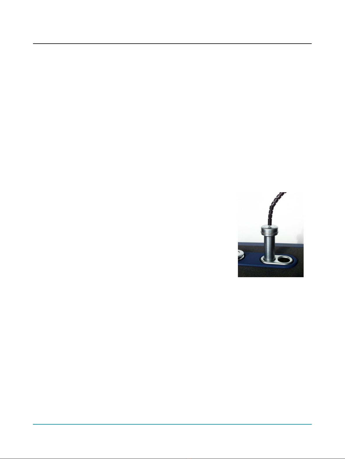
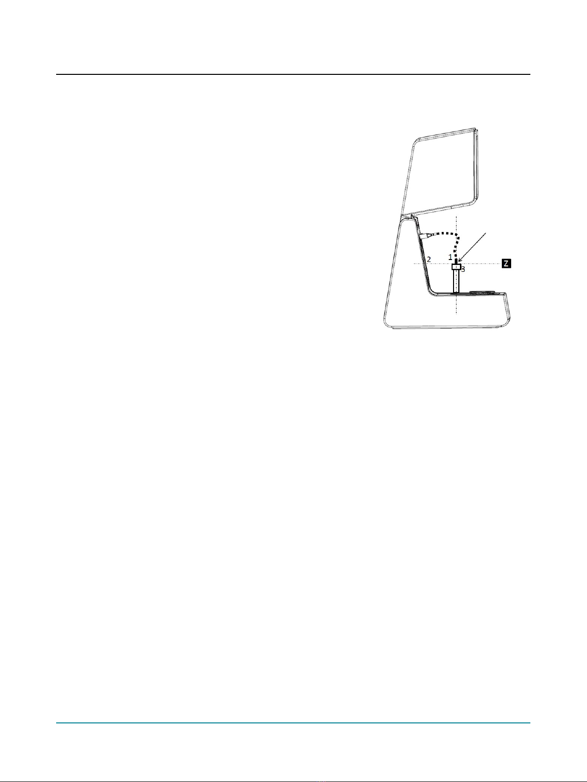
3. Position the reference microphone (1) pointing straight down from
above and centered 1-2 millimeters above the coupler meas-
urement microphone (3).
4. During calibration the microphones must have the exact same dis-
tance to the main loudspeaker (2), along the Z axis. You can ensure
this by looking at the test chamber from the side when you adjust
the reference microphone position for calibration.
5. Close the lid.
6. Select Tools (Tools)> Aurical®HIT Calibration (Aurical®HIT Cal-
ibration) > Reference Microphone (Reference Microphone).
7. Follow the on-screen instructions.
5.2 Positioning the hearing instrument for testing
How you position the hearing instrument for testing in the test chamber depends on the type of hearing instrument or
device you wish to test.
Regardless of form factor (the type of hearing instrument), the only two important things to remember are:
• Aligning directional microphones along the loudspeaker axis.
• Positioning the reference microphone as close as possible to the front microphone of the hearing instrument without
touching it.
You can position the hearing instrument to perform all standard hearing instrument tests without repositioning the hear-
ing instrument between the individual tests:
• acoustic measurements,
• inductive telecoil measurements,
• directional microphone test.
Positioning the reference microphone
– As a rule of thumb, position the reference microphone as close as possible to the front microphone of the hearing
instrument without actually touching it.
Maximum permitted distances are:
Vertically (Y axis) 8mm (above)
Sideways (X axis) ±12mm
Back-to-front (Z axis) ±3mm
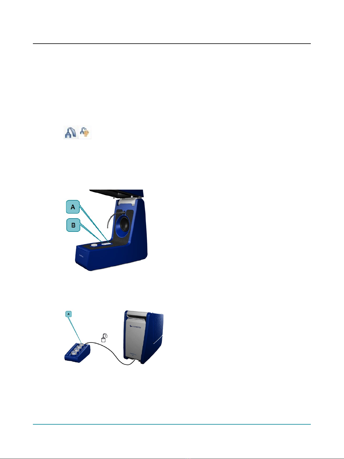
5.3 Using the battery simulator
1. Select a battery simulator and insert it in the hearing instrument.
10 AuricalHIT
5 Testing hearing instruments

With Aurical®HIT you receive a set of color-coded battery simulators, which are used to power the hearing instru-
ment. They are also used as probes for measuring the power consumption.
Color code Size IEC ANSI
Red 5 PR63 7012ZD
Yellow 10 PR70 7005ZD
Brown 312 PR41 7002ZD
Orange 13 PR48 7000ZD
Blue 675 PR44 7003ZD
2. Insert the mini-jack connector of the battery simulator in the bat-
tery simulator socket in the test chamber.
Aurical®HIT automatically detects the battery simulator.
Warning •When you have connected the battery simulator,
make sure that it does not touch other metal parts as this may
short-circuit the system.
5.4 Coupler adapters
Adapters for use with the coupler are snapped onto the coupler cavity.
• HA-2 (BTE)
Traditional BTE hearing instruments ►12
• HA-1 (ITE, RIE, thin-tube)
Thin-tube hearing instruments ►13 and ITE hearing instruments ►14
To fix the hearing instrument on the adapter, snap the adapter off the coupler cavity, and attach the hearing instrument to
the adapter outside the test chamber.
AuricalHIT 11
5 Testing hearing instruments

5.5 Traditional BTE hearing instruments
This procedure applies to any type of standard BTE hearing instruments with traditional earmolds.
Using the HA-2 adapter and BTE adapter tube
12 AuricalHIT
5 Testing hearing instruments

5.6 Thin-tube hearing instruments
This type of procedure applies to any type of thin-tube hearing instruments, including instruments with the Receiver In
the Ear (RIE)/Receiver In the Canal (RIC), and pre-bent tubing.
Using the HA-1 ITE adapter
If you place some acoustic putty on the receiver wire this will shift its resonance frequency. This will prevent the wire
from vibrating and creating feedback during testing.
AuricalHIT 13
5 Testing hearing instruments

5.7 ITE hearing instruments
This procedure applies to any type of custom hearing instruments, including ITE (In The Ear), ITC (In The Canal), CIC (Com-
pletely In the Canal).
Using the HA-1 ITE adapter
5.8 Telecoil testing
1. Position the hearing instrument in Aurical®HIT as described in Traditional BTE hearing instruments ►12,Thin-tube
hearing instruments ►13 or ITE hearing instruments ►14, so that the maximum field strength will be achieved for
the hearing instrument.
During telecoil testing Aurical®HIT automatically detects the orientation of the hearing instrument.
2. Enable telecoil mode in the hearing instrument.
3. Close the lid and start testing.
5.9 Hearing instruments with wireless transmitters (e.g. FM)
When you test hearing instruments with wireless sound transmission, it is sometimes necessary to separate the input
device (transmitter) from the output device (receiver).
• To do so, place the transmitter in Aurical®HIT and the receiver on the coupler microphone in the Accessory Box.
• To set up the Accessory Box, see The coupler assembly ►6.
14 AuricalHIT
5 Testing hearing instruments

For a detailed description of traditional FM testing, see the Aurical®HIT Reference Manual.
5.10 How to perform a standard test
The procedure
1. Launch the fitting software for the hearing instrument so that you can control its parameters.
2. Launch Otosuite and select HIT (HIT) in the Navigation (Navigation) panel.
3. Open the Test Selector (Test Selector) and select the ANSI (ANSI) or IEC (IEC) special test.
4. If Otosuite is used without Noah, you can fill out the Hearing Instrument (Hearing Instrument) fields in the lower right
corner of the Standard Tests (Standard Tests) screen. These fields are filled in automatically when you use Otosuite
with Noah together with the fitting software for the hearing instrument.
5. Position the hearing instrument so that it is ready for testing, and switch it on.
6. If you wish to measure the Battery Consumption (Battery Consumption), make sure that you connect the battery sim-
ulator.
7. Close the lid.
8. If needed, click the arrow buttons in the Measurements (Measurements) table to include the individual tests you
wish to perform.
9. Click the Start (Start) button in the top left corner of the Measurements (Measurements) table.
This will start a sequence of selected tests.
10. Make sure that you follow the on-screen instructions.
11. If you wish to redo an individual test, click on the Start (Start) button next to the test.
AuricalHIT 15
5 Testing hearing instruments

5.11 How to test the directional microphone
Directionality measurements as described in the hearing instrument test standards cannot be performed with regular desk-
top test chambers such as Aurical®HIT. Such measurements require large anechoic chambers. Small test chambers always
exhibit acoustic reflections that obscure the true directional behavior of the hearing instrument.
However, in Aurical®HIT you can make a functional test of the directional microphone in a hearing instrument. In this test,
the signal is first presented to the front of the hearing instrument and then to the back of the hearing instrument. This is
done automatically when you start a directional test. The signal used for this test is a flat spectrum Broad Band Noise, band-
pass filtered between 750 Hz and 5kHz, and presented at 70dBSPL.
The procedure
1. Position the hearing instrument as described in Traditional BTE hearing instruments ►12,Thin-tube hearing instru-
ments ►13 and ITE hearing instruments ►14 depending on the type of hearing instrument.
2. In the field Directionality Adaptation (Directionality Adaptation) in the Otosuite HIT module, you can define the dur-
ation of the signal presentation before the actual measurement is made. This value accommodates any adaptational
behavior of the hearing instrument. Adaptive directionality often takes 10 to 15 seconds or more before the dir-
ectionality of the hearing instrument is fully efficient.
3. You can either combine the Directional Test (Directional Test) with your standard test sequence by checking the
sequence checkbox, or run it separately by clicking the Start (Start) button.
The result
The Directional Test (Directional Test) result is shown as a 1/3 octave curve of the difference between the measurement
with noise presented from the main loudspeaker and the measurement with noise presented from the rear loudspeaker.
The numerical directionality result shown in the Measurements (Measurements) table indicates the average front/back
difference in the measured frequency range.
The Measurements (Measurements) table also includes the adaptation interval used in seconds.
6 Maintenance and Calibration
Warning •Under no circumstances disassemble Aurical®HIT. Contact your supplier. Parts inside Aurical®HIT
must only be checked or serviced by authorized personnel.
Calibration
Calibration of the coupler microphone, and calibration of a new reference or coupler microphone must only be performed
by authorized personnel.
Maintenance
Aurical®HIT requires no preventive maintenance except for cleaning and regular calibration of the reference microphone.
Repair
For any type of repair, please contact your supplier.
16 AuricalHIT
6 Maintenance and Calibration

Warning •For the sake of safety and in order not to void the warranty, service and repair of the device should be
carried out only by the equipment manufacturer or by service personnel at authorized workshops. In case of any
defects, make a detailed description of the defect(s) and contact your supplier.
Caution •Do not use a defective device.
6.1 Cleaning
There are no specific requirements to sterilization or disinfection of the device.
Cleaning the device
Make sure that the device is kept clean and free of dust:
• Remove dust using a soft brush.
• To clean the cabinet, use a soft, slightly damp cloth with a small amount of mild detergent on it.
Caution •Keep the unit away from liquids. Do not allow moisture inside the unit. Moisture inside the unit can
damage the instrument and it may result in a risk of electrical shock to the user or patient.
Adapters
If needed, remove any acoustic putty residue, and use an alcohol based wipe to clean the adapter.
7 Other references
For more information, refer to the AuricalFreeFit and the Probe Microphone Measurements Module Reference Manual
(English only)
For Otosuite installation instructions, see the OtosuiteInstallation Guide, on the Otosuite installation medium.
For more information, see the online Help in Otosuite, which contains detailed reference information about AuricalHIT
and the Otosuite modules.
8 Technical specifications
Type identification
Aurical®HIT is type 1082 from Natus MedicalDenmark ApS.
AuricalHIT 17
7 Other references

Acoustic stimulus generation
In closed test chamber
Frequency response, re. 1 kHz, main loud-
speaker (equalized)
125 to 200 Hz: ± 3.0 dB
200 to 2000 Hz: ± 1.5 dB
2000 to 5000 Hz: ± 2.5 dB
5000 to 10000 Hz: ± 3.0 dB
Frequency response, re. 1 kHz, rear loud-
speaker (equalized)
125 to 10000 Hz: ± 3.0 dB
Maximum output level, main loudspeaker 90 dB SPL (pure tone), 78 dB SPL (speech)
Harmonic distortion, acoustic tone out-
put, main loudspeaker
Less than 0.5 % up to 70 dB SPL, Less than 2.0 %, 70-90 dB SPL
Acoustic measurements
Frequency range, coupler microphone
(equalized)
125 to 200 Hz: ± 3 dB
200 to 5000 Hz: ± 1 dB
5000 to 10000 Hz: ± 3 dB
Battery simulator
Voltage range 0 to 2.0 V
Resolution, voltage 0.02 V
Accuracy, voltage ± 0.05 V
Output impedance range 3 to 10 ohm
Resolution, impedance 0.1 ohm
Accuracy, impedance ± 5 %
Current measurement range 0.5 to 40 mA
Current measurement accuracy ± 5 %
Tele coil
Max. field strength 31.6 mA/m
USB interface
Type: USB device port, type B
Interface: USB 2.0
Speed: High speed
Power consumption: Max. 2.5 W
Dimensions
Approximately, WxDxH 16 x 31 x 28 cm (6.3 x 12.2 x 11 in)
18 AuricalHIT
8 Technical specifications

Weight
Weight 6.3 kg (13.9 lb)
Transport and storage
Temperature: -15ºC to +55ºC (5ºF to 131ºF)
Air humidity: 10% to 90%, non-condensing
Operating environment
Operating environment Indoors
Operating temperature range 15 to 35 ºC (59 to 95 ºF)
Maximum relative humidity Maximum relative humidity 80% for temperatures up to 31ºC (88 ºF) decreas-
ing linearly to 50% relative humidity at 40ºC (104 ºF).
Altitude Up to 2,000 m (6,562 feet)
Warm-up time < 15 min
Standards
Aurical®HIT CE marked according to the Electromagnetic Compatibility Directive
2014/30/EU
Safety IEC 61010-1:2010
Test standards ANSI S3.22:2009
IEC 60118-7:2005
EMC IEC61326-1:2020
Accessories
• BTE adapter tube
• Coupler set, including 2cc coupler, and snap-on adapters HA-1 (ITE), HA-2 (BTE), and body-worn
• Elevation plate
• Reference microphone
• Coupler microphone
• Accessory Box
• Battery Probe Kit
• Accessory Box microphone cable
• USB cable
• Acoustic putty
• Ear simulator
• Aurical®HIT Reference Manual
• Aurical®HIT User Guide
AuricalHIT 19
8 Technical specifications

9 Definition of symbols
Symbol Standards
Reference
Standard Title of Sym-
bol
Symbol Title as
per Referenced
Standard
Explanation
ISO 15223-
1:2016 Refer-
ence no. 5.1.1
(ISO 7000-
3082)
Medical devices —
Symbols to be used
with medical device
labels, labelling and
information to be sup-
plied.
Manufacturer Indicates the medical device man-
ufacturer.
ISO 15223-
1:2016 Refer-
ence no.
5.1.3. (ISO
7000-2497)
Medical devices —
Symbols to be used
with medical device
labels, labelling and
information to be sup-
plied – Part 1: Gen-
eral requirements.
Date of man-
ufacture
Indicates the date when the med-
ical device was manufactured.
ISO 15223-
1:2016 Refer-
ence no.
5.1.4. (ISO
7000-2607)
Medical devices —
Symbols to be used
with medical device
labels, labeling, and
information to be sup-
plied – Part 1: Gen-
eral requirements.
Use-by date Indicates the date after which the
medical device is not to be used.
ISO 15223-1
Reference no.
5.1.5
Medical devices —
Symbols to be used
with medical device
labels, labelling and
information to be sup-
plied.
Batch or Lot code Indicates the manufacturer's batch
code so that the batch or lot can
be identified.
ISO 15223-1
Reference no.
5.1.6
Medical devices —
Symbols to be used
with medical device
labels, labelling and
information to be sup-
plied.
Catalogue num-
ber
Indicates the manufacturer’s cata-
logue number so that the medical
device can be identified.
20 AuricalHIT
9 Definition of symbols
This manual suits for next models
1
Table of contents