Nautilus Hyosung MONISAFE400A User manual

Operator Manual
MONISAFE 400A System
V01.00.01 (2014.10.7)
© 2014 Nautilus Hyosung, Inc. All Rights Reserved.

© 2014 Nautilus Hyosung, Inc. All Rights Reserved.
Revision History
Operator Manual - MONISAFE 400A System
No.
Version
Date
Description of Change
Chapter
1
V01.00.00
2013/11/08
New Publication
All
2 V01.00.01
2014/10/07
Replaced Windows XP with Microsoft© Windows© Embedded
POSReady 2009 2
© 2014 Nautilus Hyosung All Rights Reserved.
The content of this specification is protected by copyright laws.
2013. 11. 08. 1st Release

© 2014 Nautilus Hyosung, Inc. All Rights Reserved. i
Contents
Chapter 1 Preface...........................................................................................................................1-1
Purpose ........................................................................................................................................................1-1
Audience.......................................................................................................................................................1-1
Support Information......................................................................................................................................1-1
What is in This Manual .................................................................................................................................1-1
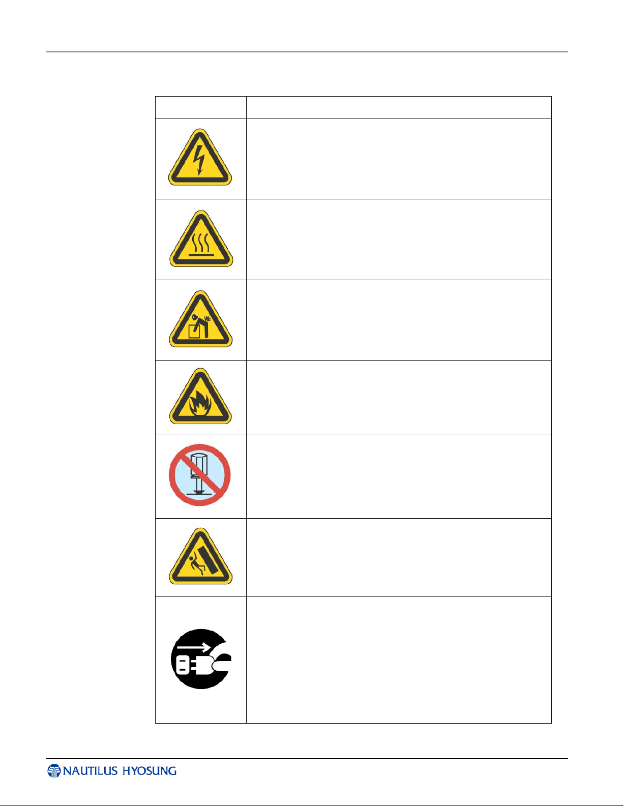
Conventions..................................................................................................................................................1-2
Safety Precautions .......................................................................................................................................1-4
Related Documents......................................................................................................................................1-6
Chapter 2 Introduction...................................................................................................................2-1
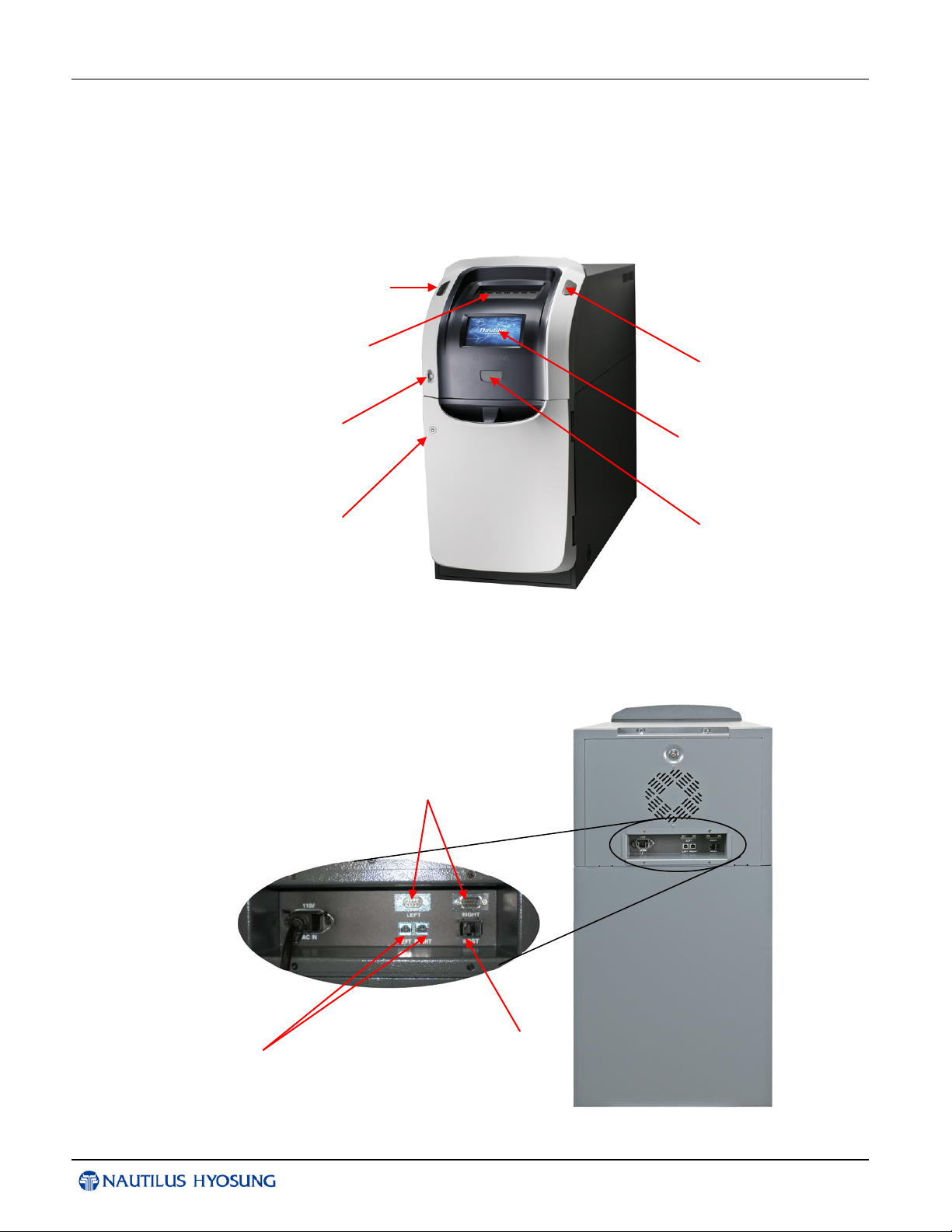
Exterior Overview············································································································ 2-1
Interior Overview············································································································· 2-2
Basic Features..............................................................................................................................................2-3
MONISAFE400A Devices.............................................................................................................................2-5
CE (Control Electronics, PC)······························································································ 2-5
Power Supply················································································································· 2-6
Bill Recycle Machine (BRM)······························································································· 2-7
Chapter 3 For the Beginning Operator..........................................................................................3-1
Opening and Closing the Exterior Door........................................................................................................3-1
Opening & Closing the Upper Front Body ············································································· 3-1
Opening the Lower Front Body··························································································· 3-2
Opening the Security Enclosure...................................................................................................................3-3
Closing the Security Enclosure.....................................................................................................................3-4
Switching Power On/Off ...............................................................................................................................3-5
Switching the Power On···································································································· 3-5
Switching the Power Off···································································································· 3-6
Power Supply Status········································································································ 3-7
Opening/Closing the Security Enclosure (Security Door) ............................................................................3-8
Cencon Lock·················································································································· 3-8
Chapter 4 Bill Recycling Machine 24 (BRM24) .............................................................................4-1
Basic Specifications......................................................................................................................................4-2
Specification and Function································································································· 4-2
External Appearance Specification...............................................................................................................4-3
Bill Conditions...............................................................................................................................................4-4
How to Open and Close the Lower Unit.......................................................................................................4-9
How to Replenish the Cassette with Bills...................................................................................................4-12
How to Remove the Bills from the Utility Cassette··································································4-18
How to Open and Close the Upper Unit···············································································4-20
How to Open and Close the Upper Body of the Machine ..........................................................................4-23
How to Remove a Jam...............................................................................................................................4-24

Operator Manual Chapter1. Preface
© 2014 Nautilus Hyosung, Inc. All Rights Reserved. 1-1
Chapter 1 Preface
Purpose
▶This manual explains how to operate the Nautilus Hyosung America’s (NHA)
MONISAFE400A. Included are instructions on replenishing the notes and how to
remove jams in the MONISAFE400A.
Audience
▶This manual has been written for anyone responsible for operating the MONISFAE400A
within bank branches, such as bank tellers, supervisors and managers.
Support Information
▶For question or if error occurs while operating the MONISAFE400A while following this
manual, contact the NHA maintenance staff or help desk. For contact information, see
your support email addresses and telephone numbers that are provided separately.
What is in This Manual
▶This manual provides operating guidelines for the MONISAFE400A and includes
detailed descriptions of:
▪Replenishing notes
▪Emptying notes
▪Removing note jams
▶All measurements in this manual are in metric with inches provided in braces [ ] or
parenthesis ( ).
▶All information described in this manual refers to licensed products of Nautilus Hyosung
Inc. It is the policy of Nautilus Hyosung Inc. to improve products as new technology,
components, software, and firmware become available. Therefore Nautilus Hyosung
Inc. reserves the right to change specifications without notice.

Chapter1. Preface Operator Manual
1-2 © 2014 Nautilus Hyosung, Inc. All Rights Reserved.
Conventions
▶Terminology
The following terminology is used in this document.
▪Customer and consumer refer to any person who transacts business through the TCR.
▪Device and unit refer to the standard and optional TCR equipment, such as monitor,
printer and dispenser.
▪Fascia refers to the entire front portion of the unit, including the portion where the
customer transacts business.
▪Module refers to a plug-in device that can be serviced or replaced.
▪Note(s) and bill(s) refer to the individual documents loaded into and dispensed from the
dispenser.
▪Servicing and maintenance refer to the supervisor, operator and technician’s tasks
performed to keep the TCR operational.
▪Screen refers to the text appearing on the customer display.
▶The following abbreviations are used in this document.
#
Abbreviations
Description
1 AD board Analog Digital Board
2 ADA The American Disabilities Act
3 AP Application Program
4 Assy Assembly
5 BRM Bill Recycle Machine
5-1
BC
Bill Checker
5-2 BMD Body Module-Down (Lower Body of the Module)
5-3 BMU Body Module-Up (Upper Body of the Module)
5-4
BRM
Bill Recycle Machine
5-5 CSM Customer Service Module
5-6 DPC Deposit Cassette
5-7
RC
Recycle Cassette
5-8 RJC Reject Cassette
5-9 TE Tape Escrow
5-10 UTC Utility Cassette
6 BATT S/W Battery Switch
7 CAM Camera Unit
8 CE Control Electronics

Operator Manual Chapter1. Preface
© 2014 Nautilus Hyosung, Inc. All Rights Reserved. 1-3
#
Abbreviations
Description
9 EP Elementary Program
10 H/W Hardware
11
I/F
Interface
12 LCD Liquid Crystal Display
13 OPL Operation Panel for Customers to Operate
14
OSD board
On Screen Display Board
15 P/S Power Supply
16 PNC Panel Control Board
17 S/W Switch
18 SIU Sensor and Indications Unit
19 SP Service Provider
20 TTU Text Terminal Unit (OPL or SPL)

Chapter1. Preface Operator Manual
1-4 © 2014 Nautilus Hyosung, Inc. All Rights Reserved.
Safety Precautions
▶Common Safety Precaution
Safety Precautions in outlined this manual provide information
on safe and proper handling of the product. Non-compliance of
the safety precautions may result in injury or damage to the
product.
This precaution symbol with sample term tells you safety
warnings during equipment handlings.
▶Please read the following instructions before operating equipment.
▪Operate equipment in the order outlined in this manual.
▪Follow precautions indicated in this manual, as well as the equipment itself.
Failure to properly address these precautions may lead to injury or damage to the
product.
▪Avoid operations not addressed in this manual.
▪If you cannot remedy system problems using the methods outlined in this manual,
please refer to contact information listed in the manual.
▪Any change or modifications in construction of this device which are not expressly
approved by the party responsible for compliance could void the user’s authority to
operate the equipment.
<Note!>
This equipment has been tested and found to comply with the limits for a Class A
digital device, pursuant to part 15 of the FCC Rules. These limits are designed to
provide reasonable protection against harmful interference when the equipment is
operated in a commercial environment. This equipment generates, uses, and can
radiate radio frequency energy and, if not installed and used in accordance with the
instruction manual, may cause harmful interference to radio communications.
Operation of this equipment in a residential area is likely to cause harmful
interference in which case the user will be required to correct the interference at his
own expense.
▶CAUTION
1. To reduce the risk of fire, use only No. 26 AWG OR LARGER Telecommunication
cord
2. Risk of explosion if battery is replaced by an incorrect type.
Dispose used batteries according to the instructions.
3. For pluggable equipment, the socket-outlet shall be installed near the equipment and
shall be easily accessible.
4. The equipment is to be secured to the building structure before operation
5. A security container shall be permitted to optionally be provided with a secondary
lock, but improper use of the secondary lock feature will reduce the security level of
the TCR.

Operator Manual Chapter1. Preface
© 2014 Nautilus Hyosung, Inc. All Rights Reserved. 1-5
▶Precaution Symbols
Symbol Description
Electrical Shock Warning
▪Do not remove cover. Only a maintenance engineer is allowed
to open the cover.
▪Do not touch. You may receive electric shock.
▪Make sure to turn off the power when servicing the equipment.
High Temperature Warning
▪Do not touch the equipment when it is running.
▪The equipment can get extremely hot and may cause a burn.
▪Make sure to close the cover before running the equipment.
Use Precaution when Moving
▪The equipment is heavy. Make sure at least 2 people lift or
move the equipment.
▪Do not attempt to move the equipment alone. You may be
injured from dropping the heavy equipment.
Fire Hazard
▪Place the equipment in an area away from any combustible
materials.
▪The equipment may catch on fire from overheating or short
circuit of the power supply unit.
Disassembly Warnings
▪Do not disassemble or modify the equipment unless you are a
certified engineer.
▪Contact the service center for maintenance, adjustments and
repairs.
▪Improper disassembly may cause fire or electrical shock.
Collapse Precautions
▪Do not place the equipment where the floor cannot sustain the
weight of the equipment, or on slanted or unstable surface.
▪Equipment may fall and cause injury or damage.
Unplug the Equipment
▪Stop using the equipment immediately if it smokes, emits an
unusual smell, makes abnormal sounds, or if liquids or other
foreign materials enter the equipment.
▪If the above-mentioned abnormalities occur, immediately turn
off the power, unplug the equipment and contact the service
center.
▪If you ignore these symptoms, the equipment may catch on fire
or cause electric shock.

Chapter1. Preface Operator Manual
1-6 © 2014 Nautilus Hyosung, Inc. All Rights Reserved.
Related Documents
▶The following documents complement this one.
▪Installation Manual
▪Service Manual
▪VDM Manual
▪Error Code Manual
Contact your NHA representative to obtain copies of these documents.

Operator Manual Chapter2. Introduction
© 2014 Nautilus Hyosung, Inc. All Rights Reserved. 2-1
Chapter 2 Introduction
Exterior Overview
►The following picture shows the front of the MONISAFE400A and its key units.
►The following picture shows the rear of the MONISAFE400A.
LCD for Customer
Operation
Stand-by
Switch
For USB
Communication
For Host
Teller Hold
Indicator
Bill Recycle
Machine
Upper Front Door
Key
Lower Front
Door Key
For Serial
Communication
Teller Hold
Indicator

Chapter2. Introduction Operator Manual
2-2 © 2014 Nautilus Hyosung, Inc. All Rights Reserved.
Interior Overview
►The MONISAFE400A consists of the safe where banknotes are stored and the upper
body where the CE and the power supply are installed. The interior and key units are
as follows.
<Note!>
DO NOT use the Main Power Switch when you want to turn off the power. It may
damage the operating system or destabilize the control electronics in TCR.
Upper Body
of BRM
Lower Body
of BRM
Lower Front
Door
Security
Enclosure

Operator Manual Chapter2. Introduction
© 2014 Nautilus Hyosung, Inc. All Rights Reserved. 2-3
Basic Features
▶Key features of MONISAFE400A are highlighted in the following list:
Main Controller
CPU
Intel ATOM N450 1.66Ghz
Memory
1GB
Up to 2GB
HDD
3.5”, 320GB
SATA Type
Operating System
Microsoft© Windows©
Embedded POSReady 2009
ODD
N/A
Graphic
Embedded Gen3.5+GFX Core
800 X 480
PCI Slot
2 Slot
Serial Ports
6 Ports
SATA
2 Ports
USB Ports 4 + 4 Ports
USB 2.0(User Port :
4EA)
LAN
Gigabit LAN
On-Boarded
POWER
12V
Customer Operation
LCD Type
7” Wide TFT LCD
600cd/m2
Input Method
Register type Touch Screen
USB Type
Bill Recycle Machine
Interface Type
USB 1.1(Main), USB 2.0(BC)
Sutter type
Automatic Shutter
1 Slot
Functional Architecture
6 Recycle / 1 Reject / 1 Utility
Cassette
Dispense
Denomination
6 Denomination
(1, 5, 10, 20, 50 , 100 USD) 6 Recycle CST
Dispense MAX
200 bills per Transaction
Method
Bundle
Deposit
Denomination
6 Denomination
(1, 5, 10, 20, 50 , 100 USD) 6 Recycle CST
Input MAX
200 bills per Transaction
Method
Bundle
Cassette
Install Max
Reflux 15,150 bills
Non-Reflux 16,400
Dispense CST
Reflux 2,750 per Cassette
Non-Reflux 3,000 per
Cassette

Chapter2. Introduction Operator Manual
2-4 © 2014 Nautilus Hyosung, Inc. All Rights Reserved.
Deposit CST
Dispensing Speed
8 notes/sec
Power Supply
Main Power
Input Voltage /
Current
100~127Vac ±10% / 13.5A
200~240Vac ±10% / 6.5A
Frequency
47~63Hz
NORMAL:50/60Hz
Battery
N/A
Safety & Security
Specification
UL291 Level-1 Safety
Locking device
Cencon Lock
Additional Function
Teller Hold Indicator
Left, Right
Door Sensor
Safety 1EA
Interface
2 USB, 2 Serial, 1 TCP/IP
Temp, Vibration Sensor
1EA
<Note!>
* is the reference value when the bill thickness is 0.1mm [0.0039 inches].

Operator Manual Chapter2. Introduction
© 2014 Nautilus Hyosung, Inc. All Rights Reserved. 2-5
MONISAFE400A Devices
CE (Control Electronics, PC)
▶The Control Electronics mainly consist of a motherboard, HDD, and so on.
The basic functions of the control electronics used in the TCR are similar to that of a
personal computer with exception of a multiple USB HUB used to communicate with
several devices, such as a Bill Recycle Machine.
Basic Specification of Control Electronics
▪Intel ATOM N450 1.66Ghz
▪1GB Memory
▪3.5”, 320GB HDD
▪Microsoft© Windows© Embedded POSReady 2009
▪Embedded Gen3.5+GFX Core (800X480)
▪2 PCI Slot
▪6 Serial Ports
▪SATA, 2 Ports
▪4+4 USB Ports (USB 2.0)
▪Gigabit LAN (On-Boarded)
▪12V Power (DC-DC)

Chapter2. Introduction Operator Manual
2-6 © 2014 Nautilus Hyosung, Inc. All Rights Reserved.
Power Supply
▶The power supply unit converts AC power to DC power and provides the voltage to
various modules within the system. The power supply unit allows the user to turn on/off
the system, enter power-failure mode, and perform other sequences.
Main Power
Input Voltage / Current
100~127Vac ±10% / 13.5A
200~240Vac ±10% / 6.5A
Frequency 47~63Hz NORMAL:50/60Hz

Operator Manual Chapter2. Introduction
© 2014 Nautilus Hyosung, Inc. All Rights Reserved. 2-7
Bill Recycle Machine (BRM)
▶The idea of recycling is to make the cash that is paid in during deposit transactions
available again for dispensing. This considerably lengthens the replenishment or
emptying cycles on cash-in/cash-out systems and, at the same time, the cash
holding per system can be reduced.
Basic Specification of Bill Recycle Machine
• Automatic Shutter (1 Slot)
• 6 Recycle / 1 Reject / 1 Utility Cassette supported
• Dispensing 200* bills per transaction by bundle (47.2mm [1.86inch])
• Depositing 200* bills per transaction by bundle (48mm [1.89inch])
*For 0.1mm [0.0039inch] thickness bill
Upper Body
of BRM
Lower Body
of BRM

Operator Manual Chapter3. For the Beginning Operator
© 2014 Nautilus Hyosung, Inc. All Rights Reserved. 3-1
Chapter 3 For the Beginning Operator
Opening and Closing the Exterior Door
►The front body door of upper/lower can be opened independently of each other with the
key.
The security enclosure of the MONISAFE400A can be accessed after you open the
lower front door.
Opening & Closing the Upper Front Body
▶Opening the upper front body as follows.
1. Turn the key-handle clockwise and open the upper front body as pictured below.
2. Remove the screws from the upper front and pull the front body as pictured below.
3. To close the front body, use the reverse order of above procedure.
Opening
Closing

Chapter3. For the Beginning Operator Operator Manual
3-2 © 2014 Nautilus Hyosung, Inc. All Rights Reserved.
Opening the Lower Front Body
▶Close the upper & lower front body door as follows.
1. Insert the system key in the lower front body.
2. Turn the key clockwise and open the lower front body as pictured below.

Operator Manual Chapter3. For the Beginning Operator
© 2014 Nautilus Hyosung, Inc. All Rights Reserved. 3-3
Opening the Security Enclosure
▶Open the Security Enclosure as follows.
1. Open the lower front body with key.
2. Unlock the security door, refer to the relevant instructions detailed under “Opening/
Closing The Security Enclosure (Security Door)” for the configuration of
MONISAFE400A
3. Turn and pull the Handle.
Cencon Lock
Handle

Chapter3. For the Beginning Operator Operator Manual
3-4 © 2014 Nautilus Hyosung, Inc. All Rights Reserved.
Closing the Security Enclosure
▶Close the Security Enclosure as follows.
1. Lock the security door, refer to the relevant instructions detailed under “Opening/
Closing The Security Enclosure (Security Door)” for the configuration of
MONISAFE400A
2. Turn the Handle.
3. Close the lower front door.
Cencon Lock
Handle
Table of contents