Nav TV BMW12N-DYNAMIC KIT User manual

BHM
10/08/18
NTV-DOC255
Agreement: End user agrees to use this product in compliance with all State and Federal laws. NAV-TV Corp. would not be held liable for
misuse of its product. If you do not agree, please discontinue use immediately and return product to place of purchase. This product is
intended for off-road use and passenger entertainment only.
1 | P a g e
3950 NW 120th Ave, Coral Springs, FL 33065 TEL 561-955-9770 FAX 561-955-9760
www.nav-tv.com i[email protected]m
BMW12N-DYNAMIC KIT
NTV-KIT717
Overview
The BMW12-N kit interfaces 2 video inputs (including a backup camera) to the factory media
screen in select 2012+ BMWs with the 6-pin video connector (at the screen). This interface
generates steering-based guidelines while in reverse for added convenience. NOTE: 2017 year
‘EVO’ touch-screen monitors are NOT compatible with this interface.
Kit Contents
Power/CAN Harness
LVDS Video
cable
BMW12-N Interface
NTV-INT244
Remote (menu control)
IR Eye Harness
Screen
Connector
HD-LINK Optional KIT800

BHM
10/08/18
NTV-DOC255
Agreement: End user agrees to use this product in compliance with all State and Federal laws. NAV-TV Corp. would not be held liable for
misuse of its product. If you do not agree, please discontinue use immediately and return product to place of purchase. This product is
intended for off-road use and passenger entertainment only.
2 | P a g e
|DS 1-4 are install dependent |
Interface Connectors
Dip Switch settings*
Dip SW:
1
2
3
4
5
6
7
8
9
10
UP
KEEP
UP
SKIPS
V1
SKIPS
V2
RVC
OFF
CAN
SETTING
CAN
SETTING
CAN
SETTING
HIGH
RES
VEH
SETTING
KEEP
DOWN
DOWN
KEEP
UP
ENABLES
V1
ENABLES
V2
RVC
ON
CAN
SETTING
CAN
SETTING
CAN
SETTING
LOW
RES
VEH
SETTING
KEEP
DOWN
NOTE: reset power after adjusting dip switches.
*See next page for verified dip switch settings.
Expansion board
control (optional)
LCD IN (LVDS from
OEM screen)
Dip Switches
(see below)
Power/CAN
OUOUT
RGB INPUT
OUOUT
HDMI Cable from HD-LINK
LCD OUT (Provided
LVDS Cable)
NOT USED

BHM
10/08/18
NTV-DOC255
Agreement: End user agrees to use this product in compliance with all State and Federal laws. NAV-TV Corp. would not be held liable for
misuse of its product. If you do not agree, please discontinue use immediately and return product to place of purchase. This product is
intended for off-road use and passenger entertainment only.
3 | P a g e
Verified Dip Switch Settings

BHM
10/08/18
NTV-DOC255
Agreement: End user agrees to use this product in compliance with all State and Federal laws. NAV-TV Corp. would not be held liable for
misuse of its product. If you do not agree, please discontinue use immediately and return product to place of purchase. This product is
intended for off-road use and passenger entertainment only.
4 | P a g e
BMW12-N Interface Installation (5 Series example)
1. The BMW12-N intercepts two OEM harnesses in two locations: the iDrive knob and the
screen. You must gain access to both places for proper installation.
a. Access the rear of the screen by removing the dashboard panel (clips only) and
then removing (2x) Torx T20 screws securing the screen to the sub-dash.
2. To access the iDrive harness, remove the panel surrounding it (may have Torx screw
securing to sub dash)
3. Lift up the lower
dash panel and
disconnect 4-PIN plug
powering the iDrive
knob.
4. Connect provided 4-
PIN T-Harness in
between iDrive knob and
OEM harness as shown.
Remove dash
Screen flips up
Remove plastic cover
Remove Torx T20

BHM
10/08/18
NTV-DOC255
Agreement: End user agrees to use this product in compliance with all State and Federal laws. NAV-TV Corp. would not be held liable for
misuse of its product. If you do not agree, please discontinue use immediately and return product to place of purchase. This product is
intended for off-road use and passenger entertainment only.
5 | P a g e
4. Replace the lower dash panel (with iDrive knob) back to sub-dash.
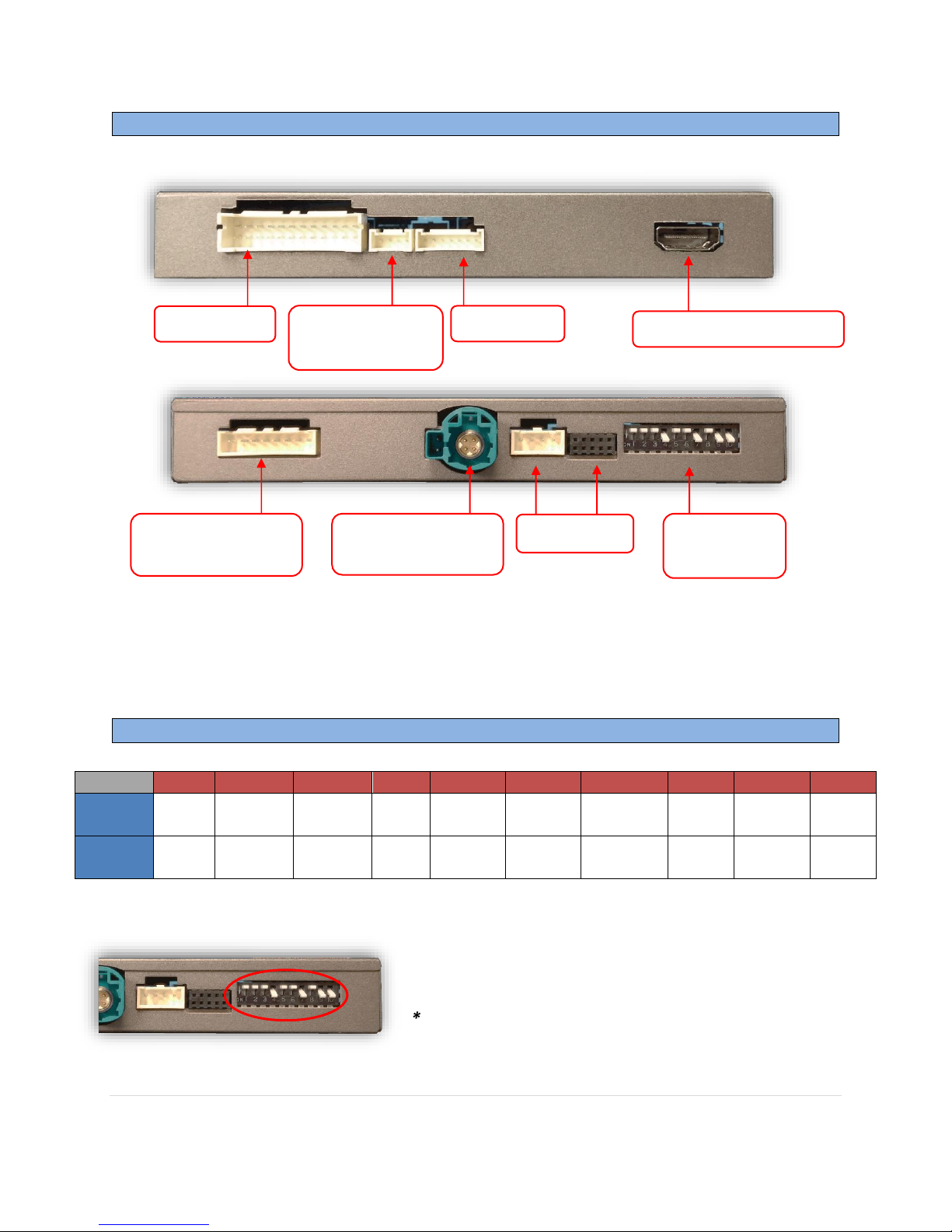
5. Disconnect the OEM screen LVDS video cable and connect it to the port on the BMW12-N
labeled ‘LCD-IN’.
6. Connect the provided LVDS Video Cable to the port on the BMW12-N labeled ‘LCD-OUT’ and
the other end back to the screen.
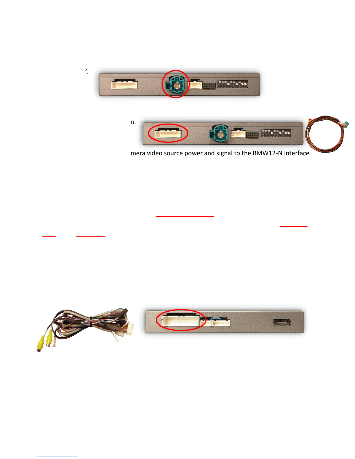
7. Install and run the reverse camera video source power and signal to the BMW12-N interface
location and connect to the RCA labeled ‘CAMERA’. Power your camera with an ACC source
(cigarette lighter) or use the violet wire to trigger a relay for reverse 12v (+) only.
NOTE: using the purple wire directly to power your camera is not recommended due to potential
current issues (iDRIVE power has only 3 amp fuse).
NOTE2: If this vehicle is equipped with a manual transmission, chances are the module will not
switch using CAN data –if this is the case, run a reverse signal from the reverse light through a
relay to the green wire on the module for reverse switching.
8. Optional: If installing a secondary camera or AUX video source, connect signal RCA to the
RCA on the BMW12-N interface labeled ‘AVIN’.
7. After DIP switch settings have been set (see page 2), connect the 24-PIN power connector to
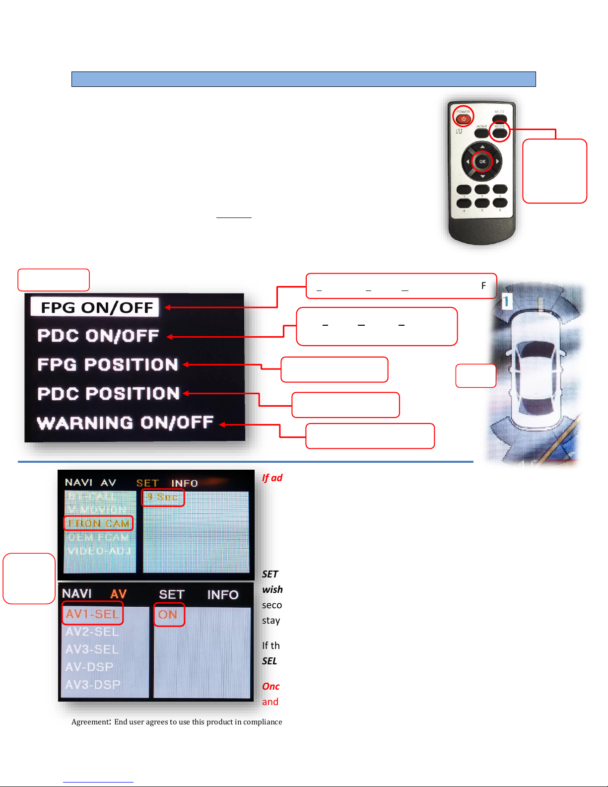
the BMW12-N interface labeled ‘POWER CAN’. Proceed to Menu Options section if necessary
(front camera settings, etc) or to BMW12-N Operation.

BHM
10/08/18
NTV-DOC255
Agreement: End user agrees to use this product in compliance with all State and Federal laws. NAV-TV Corp. would not be held liable for
misuse of its product. If you do not agree, please discontinue use immediately and return product to place of purchase. This product is
intended for off-road use and passenger entertainment only.
6 | P a g e
If adding a front camera OR Aux Video source:
1. Disconnect POWER/CAN Harness from interface
2. Place DIP SWITCH 1 in the DOWN position, reconnect power
3. Press and hold the iDRIVE knob ‘MENU’to activate the AUX screen
4. Press OK button on remote 4 times, then press POWER
SET –FRON CAM must be turned on if adding a front camera and the user
wishes for automatic front camera switching. Options for 5, 7, 9 or 11
seconds are user-selectable for the length of time the front camera input
stays active once the vehicle is placed out of reverse.
If the user wants only an AUX video input without front camera, set AV1-
SEL to ON
Once finished with settings, place DIP SWITCH 1 back into the UP position
and reset power to interface.
Menu Adjustments
Before you start:
•The IR-Eye must be connected
•Make sure the car’s ignition is on and radio is on
•You must be in Reverse Camera mode OR AUX Video mode (see
below):
•
Reverse Camera Mode adjusts Reverse Camera Settings
•
AUX Video Mode adjusts AUX Video Settings
•Press the OK BUTTON 4 times (numbers will display per press),
then press POWER.
•The OSD Menu will appear on screen (auto-time out in about 5
seconds if no action occurs).
Functional Parking Guidelines ON/OFF
Parking Distance Control
ON/OFF (while in reverse)
Adjust FPG Position
Adjust PDC Position
‘Safe to move?’ ON/OFF
PDC
Return
(AUX VID
menu
control)
RVC Menu
AUX
VIDEO
Menu

BHM
10/08/18
NTV-DOC255
Agreement: End user agrees to use this product in compliance with all State and Federal laws. NAV-TV Corp. would not be held liable for
misuse of its product. If you do not agree, please discontinue use immediately and return product to place of purchase. This product is
intended for off-road use and passenger entertainment only.
7 | P a g e
Adding HD-LINK Adapter (HDMI Input)
Follow the instructions below when adding the HDMI adapter
(HD-LINK) to enable HDMI input to the OEM screen:
1. Put dip switch #1 in the DOWN position.
2. Activate the ‘NAV INPUT’ by holding the ‘MENU’ button on
the iDRIVE knob.
3. Once ‘NAV INPUT’ shows on the screen, on the remote
press the OK BUTTON 4 times, then press POWER.
4. Navigate to the ‘NAVI’ section.
a. Select ‘HDMI-SEL’
b. Choose ‘HD95E’
c. Press MODE on the remote to return and exit the OSD menu
(or let it time out).
5. Replace dip switch #1 to the UP position.
6. Connect the black wire to ground (-) and the red wire to ACC power
(+) from the main power connector on the HD-LINK adapter. The
RCA’s on this plug provide audio from the HDMI source.
Green Trigger wire setup
This module includes a green input wire for analog triggering of either the Reverse camera input or the
‘AVIN’ input (yellow RCAs), selectable through the AV menu. This allows for adding multiple cameras
through the use of an SVS-6 switcher, etc. Follow the steps below adjust this feature. NOTE: by default,
the green wire will trigger the Reverse camera input RCA.
1. Put dip switch #1 in the DOWN position. When this section is complete, return switch #1 UP.
2. Activate the ‘NAV INPUT’ by holding the ‘MENU’ button on the iDRIVE knob.
3. Once ‘NAV INPUT’ shows on the screen, on the remote press the OK BUTTON 4 times, then
press POWER.
4. Navigate to the ‘SET’ section.
oSelect ‘REVERSE WIRE’
oChoose ‘AV1’, ‘REAR’ or ‘REAR MODE’ (explanations below)
oPress MODE on the remote to return and exit the OSD menu (or let it time out).
oTest by sending temporary power (12v +) to the green wire labeled reverse.
REAR MODE shows the ‘CAMERA’
RCA (with dynamic lines) when the
green reverse wire is triggered.
REAR shows the ‘CAMERA’ RCA
(with no lines) when the green
reverse wire is triggered.
AV1 shows the ‘AVIN’ RCA when the
green reverse wire is triggered.

BHM
10/08/18
NTV-DOC255
Agreement: End user agrees to use this product in compliance with all State and Federal laws. NAV-TV Corp. would not be held liable for
misuse of its product. If you do not agree, please discontinue use immediately and return product to place of purchase. This product is
intended for off-road use and passenger entertainment only.
8 | P a g e
BMW12-N Installation Diagram

BHM
10/08/18
NTV-DOC255
Agreement: End user agrees to use this product in compliance with all State and Federal laws. NAV-TV Corp. would not be held liable for
misuse of its product. If you do not agree, please discontinue use immediately and return product to place of purchase. This product is
intended for off-road use and passenger entertainment only.
9 | P a g e
BMW12-N Operation
•Once all connections are made and dip switches are set properly, placing the vehicle in
reverse will display the connected camera with dynamic guidelines for convenience*.
•Additionally, see below for AUX/Front camera activation using factory buttons.
Hold (3 sec): Activate
AUX/Front Camera
video input
Hold (3 sec): Change
AUX/Front Camera view
(60/40 split, etc)
Hold (3 sec) WHEN
IN REVERSE: 2013-
2015 3,5,7,X series:
Change Rear
Camera view
(60/40 split, etc)
Hold (3 sec) WHEN IN
REVERSE: 2013-2015 1
series/MINI: Change
Rear Camera view
(60/40 split, etc)
*NOTE: Some 3-series vehicles steering wheel data
is not present, therefore turning lines are not
supported on some 3-series vehicles.
Table of contents
Other Nav TV Dashcam manuals