NAVAC NRRD User manual

User Manual
NRRD
SAVE THIS MANUAL
FOR FUTURE REFERENCE
Recovery Unit
NAVACInc.
www.NavacGlobal.com
MADE IN CHINA
Tel/Fax: +1 877 MY-NAVAC
8
77 696 2822

Empowering you to work smarter
Read the operating manual carefully before use, so you could fully understand the safety,
specifications, as well as operating procedures for the recovery unit.
Please make sure the product received is the same one you ordered and the accessory and
operating manual are included. Please check the product for shipping damage. Contact your local
distributor if a problem is found.
01
GENERAL SAFETY
02
04
05
06
TABLE OF CONTENTS
07
08
09
10
Use information
GENERAL SAFETY
OPERATION MANUAL
SPECIFICATIONS
CONTROL PANEL
PARTS DIAGRAM
WIRING DIAGRAM
OPERATING INSTRUCTIONS
1. Initial Purge
2. Recovery Process
3. Self-purge Process
4. Push/Pull Mode
TROUBLESHOOTING
11
12
Notice Classifications
Warning
Indicates procedures that must be strictly followed to prevent hazards to people or euqipment.
Note
Indicates procedures must be strictly followed to prevent damage or destruction of the unit.
Matters Needing Attention
Warning
Strictly follow instruction and procedures. This could prevent damage of the unit as well as hazard
to people and equipment.
Only a certified technician can operate this recovery unit.
Before turning on the recovery unit, make sure the electrical power supply is grounded.
When using an extension cord, verify the power cord is properly connected and grounded.
If the original power supply cord is damaged, choose the properly rated replacement, or you may
buy the replacement directly from your authorized wholesaler.
If the unit stops working, you must disconnect the power before attempting any repairs.
Make sure the extension cord is rated for the power supply and amperage of the recovery unit.
Only certified refrigerant tanks are to be used. Only use recovery tanks with a Service Pressure
400 PSI and Test Pressure 800 PSI. Do not fill the recovery tank over 80% capacity to make sure
that there is enough space for liquid expansion. Overfilling of the tank may cause an explosion.
Always wear safety goggles and protective gloves while working with refrigerants to protect your
skin and eyes from injury.
Do not use this equipment near flammable liquids or gasoline.
An accurate electronic scale is needed to prevent overfilling the recovery tanks.
It's not suitable for class A3 refrigerants and toxic refrigerants of class B2, B3.
Be sure the work area is thoroughly ventilated.
Please boot check before connect with refrigerant:
1). please check if wind exsits around the condensator to judge whether the fan is normal.
2). connect valve to air outlet , turn the knob on recovery unit to "FAST" position to recovery
air. The exhaust pressure rise to 558 psi within 1 min, then high voltage switch action,
recovery function automatic stop.
01
1.
2.
1.
2.
3.
4.
5.
6.
7.
8.
9.
10.
11.
12.
13.
14.
Empowering you to work smarter

03
02
Note
Be sure that unit is connected to the correct voltage.
When using an extension cord it should be minimum of 12 AWG and no longer than
75 feet, otherwise it may cause a voltage drop causing damage the compressor.
The input pressure of the unit should not exceed 26bar (377.1psi).
The unit needs to be paced on even surface otherwise it will lead to vibration, noise or even physical
damage.
Do not expose the equipment to heat of direct sun, and cover if used in the rain.
The ventilation opening of the unit must not be blocked.
If the overload protection opens, allow at least 5 minutes before attempting to reset.
If this unit has an oil separator, it will only clean the refrigerant during vapor recovery process and
recycling of the refrigerant through the machine.
When recovering more than 20 lbs of refrigerant, you will need to remove oil from the oil separator.
OPERATION MANUAL
Do not mix different refrigerants together in one tank. They cannot not be separated or used.
Before recovering refrigerant, the recovery tank should be under vacuum level of 29.6”, which is for
purging non-condensable gases.Each tank was full of nitrogen when it was manufactured and must
be evacuated before the first use.
The switch should be at 0ff Position before operation. All valves must be closed, the input and output
fittings should be covered with protective caps when the unit is not in operation, as air and moisture
are harmful to the recovery machine, shortening the life span of the unit.
A filter-drier should always be used and should be replaced frequently. You must change the filter-
drier when recovering different refrigerants. To insure normal operation of the unit, use only filter-
driers specified by NAVAC. High quality filter driers will give the best service.
Special caution is needed when recovering refrigerant from a shorted system, and two filter- driers
are needed.
This unit has an Internal High Pressure Shut-Off switch. If the pressure inside the system is above
the rated shut-off pressure (see specification), compressor will automatically shut off and the high
pressure alarm light will turn on. To restart the compressor, lower the internal pressure (output
gauge shows less than 30 bar/435.1 PSI). After the high pressure alarm light turns off, press the
reset button, and turn on power to restart the compressor.
If the high pressure protection trips, please find out the cause and fix it before restarting the unit.
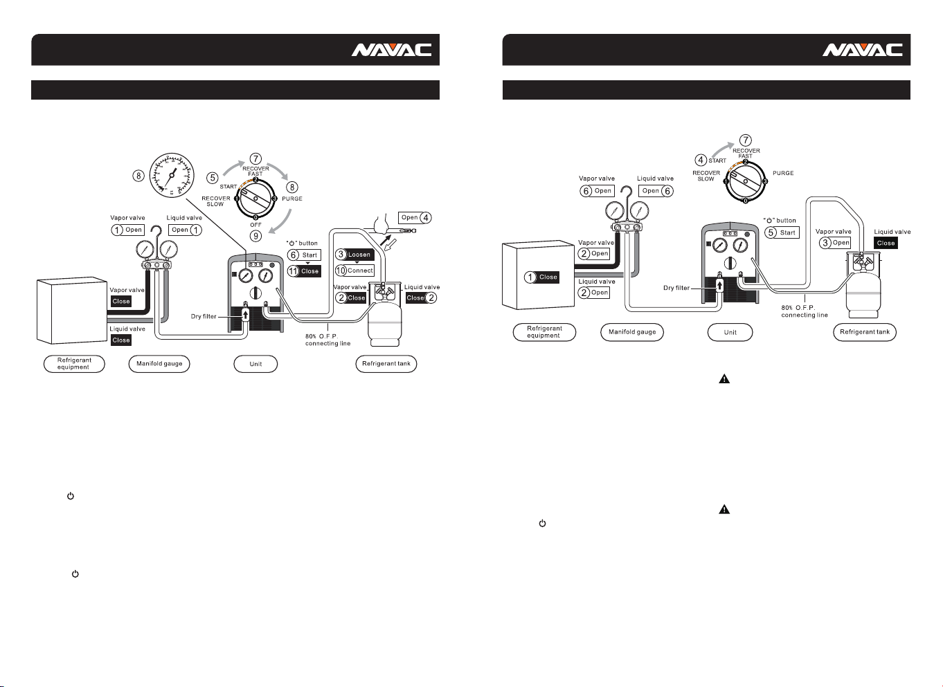
1.
2.
3.
4.
5.
6.
7.
8.
9.
1.
2.
3.
4.
5.
6.
This recovery machine can be used with tanks that have a float level sensor. Connect the recovery
unit and the tank with the 80% O.F.P. Cable. When the liquid refrigerant reaches 80% capacity of
the tank, the recovery unit will automatically shut off and the Red Alarm Light turns on. Before
restarting, change for an empty tank.
Please press button when start or stop the unit. The light is on when compressor runs.
If the refrigerant tank has no float level sensor, please take the 80% O.F.P Cable off. Otherwise the
recovery unit will not start. In this case, an electric scale is required to monitor the recovered
refrigerant weight. DO NOT OVERFILL THE TANK!
In order to get maximum recovery speed, a hose with inner diameter bigger than 5/32” is
recommended, and should be 5 feet or shorter.
While recovering large amounts of liquid, use the Push/Pull Mode.
After recovery, make sure no refrigerant is left in the unit. Follow the Purge Operation carefully.
Liquid refrigerant remaining in the unit may expand and damage the components.
If the unit is to be stored or not used for any length of time, we recommend that it be completely
evacuated of any residual refrigerant and purged with dry nitrogen.
Connection hoses with check valves are recommended to prevent refrigerant loss.
The intake port is equipped with filter screen, so clean it frequently.
The Low Pressure Gauge shows the pressure of the intake port of the compressor and the High
Pressure Gauge shows the pressure of the outlet port of the recovery unit.
After use, turn the knob to 0ff position.
1. The input valve of the refrigerant tank is closed—open the valve will help solve the problem.
2. The connecting hose between the recovery unit and refrigerant tank is plugged — close all
valves, check the hose and replace it if necessary.
3. The temperature of the refrigerant tank is too high, pressure is too high—cool down the tank
with cold water or give it time to cool down until pressure will come back to normal.
Cause of High Pressure Protection and Troubleshooting:
7.
8.
9.
10.
11.
12.
13.
14.
15.
16.
17.
Note
Empowering you to work smarter Empowering you to work smarter

05
04
SPECIFICATIONS
NRRD
Motor 1 HP
10 A
30 lbs
Notice
The flow rate of vapor is direct
proportion to inlet pressure.
CONTROL PANEL
20 40 60 80 100 120 140 160 180
0.2
0.4
0.6
0.8
1.0
1.2
1.4
1.6
lb/min
Flow Rate
psi
Inlet Pressure
NRRD
Category III: R-12, R-134a, R-401C, R-500
Category Ⅳ:
Category V: R-402A, R-404A, R-407A, R-407B, R-410A, R-507
R-22, R-401A, R-401B, R-402B, R-407C, R-407D,
R-408A, R-409A, R-411A, R-411B, R-412A, R-502,
R-509
Oil-less, Air-cooled, Piston style
558 psi / 38.5 bar
Max Current Draw
Compressor
Automatic Safety Shut-Off
Dimension 18" × 10" × 14"
Weight
Refrigerant Type
110V / 60Hz
Power Supply
Recovery Rate
0.46
0.49
4.3
11.66
R-22 R-134a R-410a
Direct Vapor
Direct Liquid
Push / pull Liquid
0.35
4.1
9.3
0.33
5.64
16.71
High Temp Vapor
Empowering you to work smarter Empowering you to work smarter

06 07
PARTS DIAGRAM
No.
1
2
3
4
5
6
7
8
No.
9
10
11
12
13
14
15
O.F.P.Cable
Front Panel
Control Valve
Copper Pipes
Junction Box Cover
Compressor
Running Capacitor
Circuit Board
Electronic Starter
Starting Capacitor
Fan
Fan Cover
Power Supply Cord
Base
Cover
WIRING DIAGRAM
No.
1
2
3
4
5
6
7
8
9
Graphics Code
XS
FR
ES
M1
C1
C2
ST
TC
HP
Power Outlet
Overload Protection Device
Electronic Starter
Compressor Motor
Start Capacitor
Running Capacitor
Motor Thermal Potectors
Electronic Transformer
High Pressure Switch
No.
10
11
12
13
14
15
16
17
18
Graphics Code
LP
OFP
d1
d2、d3
SW
HL
CTR
K1
Low Pressure Switch
80% O.F.P. Swiich
Green Indicator
Red Indicator
Power Button
Indicating Lamp
Control Moduel
Relay
Component Component
Component Component
Empowering you to work smarter Empowering you to work smarter

09
08
OPERATING INSTRUCTIONS OPERATING INSTRUCTIONS
1. Initial Purge
Initial Purge
2. Recovery Process
Open the vapor and liquid valves of
refrigeration or air conditioning system
equipment.
Open the vapor valve of the refrigerant tank.
Turn the switch to the position START.
Press button.
a. Open the liquid valve for liquid recovery.
b. Open the vapor valve for vapor recovery.
Turn the switch slowly to positon 2 for faster
recovery.
When the recovery is finished, the unit gets
to the required vacuum or automatically
stops by low pressure protection.
Recovery Procedure
Connect hoses correctly and firmly. (Please
refer to the setup diagram)
Make sure all valves are closed.
Turn off the power to system equipment.
Start Operation
Note
If compressor liquid slugging occurs at position 2,
turn the switch to position START until the liquid
slugging stops.
If the recovery restarts after interruption of power or
fails to start,
2.1 Turn the switch to positon START,turn on the
power switch, press START button for liquid
recovery.
2.2 Turn the switch to position 3,turn on the power
switch, press START button for vapor recovery.
Note
Turning the switch to position 1 gets a stable
recovery of liquid with low speed of 2.6 lbs/Min.
If compressor slugging occurs at the position 1 turn
the switch slowly to position START until slugging
stops. Make sure the pressure is at zero, because it
doesn’t work at 10.
There is no need to turn off the power and it can do
the self-purge cycle automatically.
1.
2.
3.
1.
2.
3.
4.
5.
6.
7.
1.
2.
1.
2.
3.
1. Connect hoses correctly and tight according to setup diagram.
2. Open the vapor and liquid valves of manifold gauge.
3. Disconnect hose from refrigerant tank.
4. Open the output valve.
5. Turn the switch to START.
6. Press button.
7. Turn the switch to position 2 and start purging the air out of the hoses.
8. While the input gauge getting to 15" of vacuum (-1 bar), turn the switch to position 3 to start self-
purge.
9. While the input gauge getting to 15" (-1 bar) again, turn the switch to position 0 to finish self-purge.
10. Connect the hose back to refrigerant tank.
11. Press button.
Empowering you to work smarter Empowering you to work smarter

11
10
OPERATING INSTRUCTIONS OPERATING INSTRUCTIONS
3. Self-purge Process
Notice
The unit must be purged after each use;
Liquid refrigerant remained may expand and damage the
components and pollute the environment.
Self-purge Procedure
1. The unit stops automatically when recovery is finished.
2. Press button.
3. Turn the switch slowly to position 3 to start purge.
4. When the self-purging cycle is finished, the unit goes into a vacuum.
5. Turn the switch to position off.
6. Press button.
7. Close the check valve to hoses.
8. Turn off the vapor valve of refrigerant tank.
4. Push/Pull Mode
Notice
An electric scale is needed to
monitor the recover process to
prevent overfilling.
Liquid Push/Pull Mode
Connect the hoses correctly and firmly.
(Please refer to the connection diagram)
Make sure all valves are closed.
Start operation
Warning
When the electric scale shows that the refrigerant in
the tank has reached 80% capacity, turn the power
off and close the tank valves.
Open the vapor and liquid valves of the
system equipment.
Open the vapor and liquid valves of the
recovery tank.
Turn the switch to position START.
Press button.
Turn the switch to position 2 to start
push/pull mode. When the display of electric
scale stops rising or increases very slowly, it
means the liquid recovery is finished, and it
is time to switch to vapor recovery.
Turn the switch to position PURGE and follow
self-purge mode instructions to purge the
refrigerant vapor.
Turn the switch to position OFF.
Press button.
Close the vapor and liquid valves of the
system equipment
Close the vapor and liquid valves on the
recovery tank.
Connect the hoses again and recover the
vapor from the system equipment according
tto recovery mode instructions.
1.
2.
1.
2.
3.
4.
5.
6.
7.
8.
9.
10.
11.
Empowering you to work smarter Empowering you to work smarter

13
12
TROUBLESHOOTING
Empowering you to work smarter Empowering you to work smarter
Table of contents
Other NAVAC Water Pump manuals
Popular Water Pump manuals by other brands

PSL Fire & Safety
PSL Fire & Safety FIREMASTER 23 owner's manual

Etatron
Etatron eOneMa quick start guide

WOERNER
WOERNER GMG-LEZ Translation of the original operation manual

Utilitech
Utilitech 148012 manual

Weir
Weir SPM QWS 2500 XL Operation Instruction and Service Manual

Pentair
Pentair SHURFLO 4048 Installation & operation manual