CAUTION: Make the area safe and make sure that the device power supply is
off before cabling and configuration operations.
Install the sensor in compliance with EN 60079-14.
The cable gland provided on the housing is used for cable entry.
Ground the sensor using the internal grounding system.
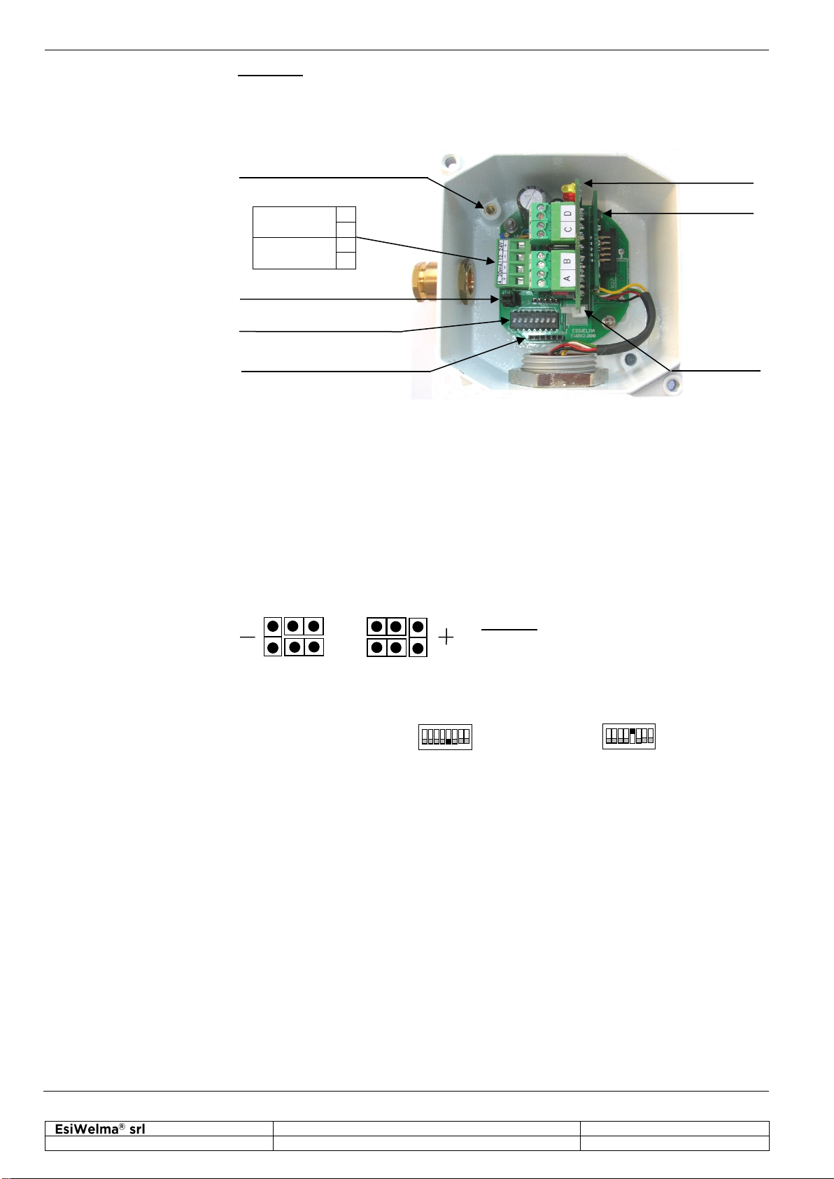
Ground connection
TB1 Terminal Board
JP2 jumper circuit
Dip-Switch S1
CN4 connector for
handheld terminal
Depending on the connecting distance, use at least 3-core cable, min. diameter
0.75mm2up to 100m, 1mm2up to 200m, 1.5mm2up to 500m.
Use shielded cable where there is a risk of electromagnetic interference.
If a relay card is used, use multi-core cable suitable for the number of connections.
Default settings of the sensor are shown in the “Technical Specifications” chapter.
In order to change the default settings, switch off the power supply, input the new
settings at the JP2 jumper circuit or at the S1 DIP switch as shown in the diagram,
then power-up again; in particular:
The default setting for the 4-20mA signal is the negative power signal. Output
reference selection should be made by JP2 triple of jumpers; to change this setting,
operator has to move JP2 jumpers as shown in the figure:
Caution: if the default settings are changed,
the connections on the TB1 terminal board will
be inverted.
Ref. at -(default) Ref. at +
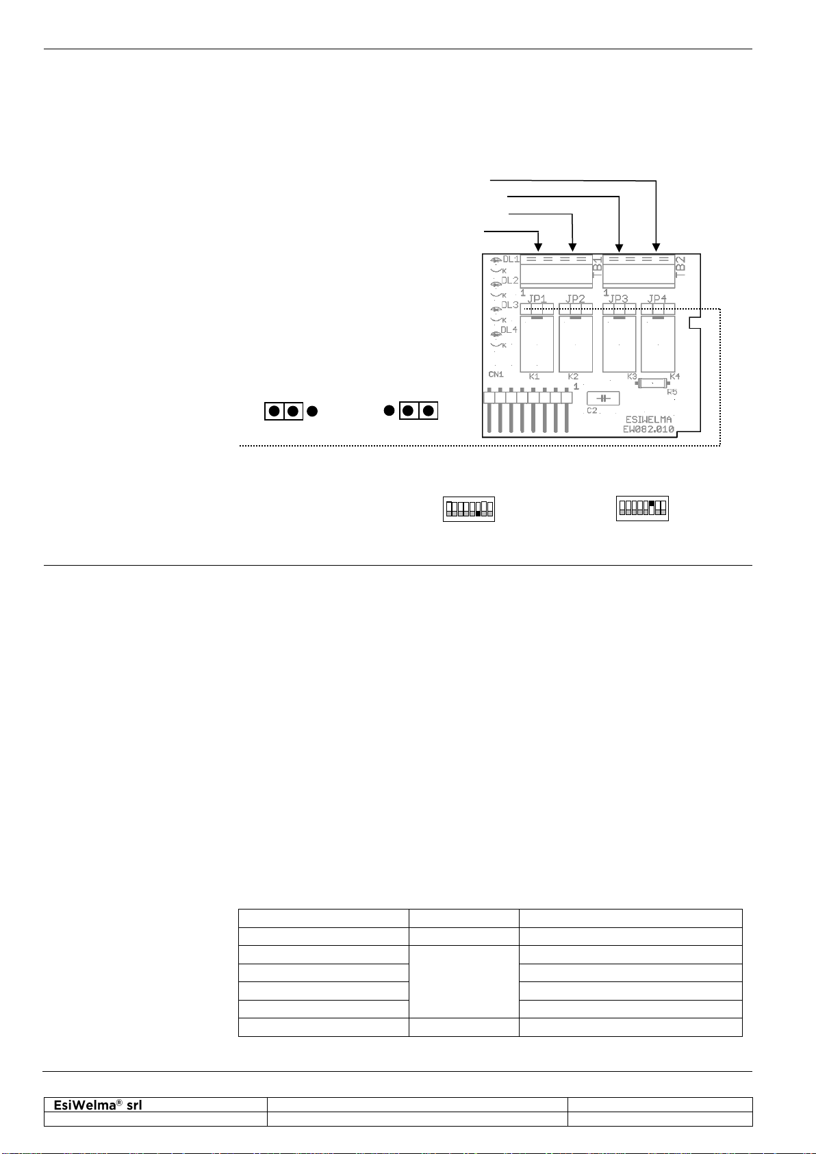
To set the operating mode of the 4...20mA signal, it is necessary to use the 5th selector
of the DIP switch at S1; in particular:
Proportional Threshold mode
To set the threshold limit values of the optional relay card, or of the threshold operating
mode of the 4...20mA signal, it is necessary to use the last selector of the DIP switch
at S1 (ignore the first four selectors); in particular, the thresholds, given in percentage
of O2, will be: