Navman G-PILOT 3380 User manual

NAVMAN
www.navman.com
www.navman.com
Pilot 3380
A U T O P I L O T S Y S T E M
Installation Manual

G-PILOT 3380 System Installation Manual NAVMAN 3
Contents
1 Introduction ..........................................................................................................................................5
1-1 A typical G-PILOT 3380 system installation . . . . . . . . . . . . . . . . . . . . . . . . . . . . . . . . . . . . . . . . 5
1-2 Using the G-PILOT 3380 system with other instruments . . . . . . . . . . . . . . . . . . . . . . . . . . . 6
1-2-1 Using other instruments . . . . . . . . . . . . . . . . . . . . . . . . . . . . . . . . . . . . . . . . . . . . . . . . . . . . . . . . 6
1-2-2 NavBus . . . . . . . . . . . . . . . . . . . . . . . . . . . . . . . . . . . . . . . . . . . . . . . . . . . . . . . . . . . . . . . . . . . . . . . . . 6
1-2-3 NMEA . . . . . . . . . . . . . . . . . . . . . . . . . . . . . . . . . . . . . . . . . . . . . . . . . . . . . . . . . . . . . . . . . . . . . . . . . . . 6
2 G-PILOT 3380 system hardware ...............................................................................................................7
2-1 What comes with your G-PILOT 3380 system . . . . . . . . . . . . . . . . . . . . . . . . . . . . . . . . . . . . . . . 7
2-2 Other parts required . . . . . . . . . . . . . . . . . . . . . . . . . . . . . . . . . . . . . . . . . . . . . . . . . . . . . . . . . . . . . . 8
3 Installation ............................................................................................................................................8
3-1 Installation sequence . . . . . . . . . . . . . . . . . . . . . . . . . . . . . . . . . . . . . . . . . . . . . . . . . . . . . . . . . . . . . 8
3-2 Installation guide . . . . . . . . . . . . . . . . . . . . . . . . . . . . . . . . . . . . . . . . . . . . . . . . . . . . . . . . . . . . . . . . . 9
3-2-1 Location guide . . . . . . . . . . . . . . . . . . . . . . . . . . . . . . . . . . . . . . . . . . . . . . . . . . . . . . . . . . . . . . . . . . 9
3-2-2 Wiring guide . . . . . . . . . . . . . . . . . . . . . . . . . . . . . . . . . . . . . . . . . . . . . . . . . . . . . . . . . . . . . . . . . . . . 9
3-3 Installing the MCU600 (Main Control Unit) . . . . . . . . . . . . . . . . . . . . . . . . . . . . . . . . . . . . . . . 10
3-4 Installing the power supplies and steering drive . . . . . . . . . . . . . . . . . . . . . . . . . . . . . . . . . 11
3-4-1 Installing the power supplies . . . . . . . . . . . . . . . . . . . . . . . . . . . . . . . . . . . . . . . . . . . . . . . . . . 11
3-4-2 Installing the steering drive . . . . . . . . . . . . . . . . . . . . . . . . . . . . . . . . . . . . . . . . . . . . . . . . . . . . 12
3-5 Installing the RFU (rudder feedback unit) . . . . . . . . . . . . . . . . . . . . . . . . . . . . . . . . . . . . . . . . 16
3-6 Installing the Compass . . . . . . . . . . . . . . . . . . . . . . . . . . . . . . . . . . . . . . . . . . . . . . . . . . . . . . . . . . 19
3-7 Installing the Gyro . . . . . . . . . . . . . . . . . . . . . . . . . . . . . . . . . . . . . . . . . . . . . . . . . . . . . . . . . . . . . . . 21
3-8 Installing the G-PILOT 3380 display unit and other instruments . . . . . . . . . . . . . . . . . .22
4 Dockside setup ..................................................................................................................................... 26
4-1 Start dockside setup . . . . . . . . . . . . . . . . . . . . . . . . . . . . . . . . . . . . . . . . . . . . . . . . . . . . . . . . . . . . .26
4-2 Calibrating the rudder feedback unit . . . . . . . . . . . . . . . . . . . . . . . . . . . . . . . . . . . . . . . . . . . .26
5 Sea trials ..............................................................................................................................................27
5-1 Calibrating the compass . . . . . . . . . . . . . . . . . . . . . . . . . . . . . . . . . . . . . . . . . . . . . . . . . . . . . . . . .27
5-2 Aligning the compass and the rudder . . . . . . . . . . . . . . . . . . . . . . . . . . . . . . . . . . . . . . . . . . .27
5-2-1 Aligning the compass (Align heading) . . . . . . . . . . . . . . . . . . . . . . . . . . . . . . . . . . . . . . . . .27
5-2-2 Aligning the Rudder (Centre rudder) . . . . . . . . . . . . . . . . . . . . . . . . . . . . . . . . . . . . . . . . . . . 27
Appendix A - Specifications - MCU600 ......................................................................................................28
Appendix B - Specifications - AP3380 Display ...........................................................................................29
Appendix C - User data ............................................................................................................................30

4 NAVMAN G-PILOT 3380 System Installation Manual
Important
It is the owner’s sole responsibility to install and use the instrument and transducer/s in a manner
that will not cause accidents, personal injury or property damage. The user of this product is solely
responsible for observing safe boating practices.
The choice, location, and installation of all components in any autoG-PILOT system is critical. If
installation is not correct, the unit can not perform at its designed potential. If in doubt, consult
your Navman dealer. Ensure that any holes that cut are in a safe position and will not weaken the
boat’s structure. If in doubt, consult a qualified boat builder.
Using the G-PILOT 3380 system :
The G-PILOT 3380 system is intended as an aid to save a helmsman from having to steer for
long periods of time, not as the main means of steering the boat.
The G-PILOT 3380 system is not intended for use in extreme weather, in adverse conditions or
in water near other boats, dangerous waters or land.
The G-PILOT 3380 system can not control the boat better than a helmsman. In adverse
conditions steer the boat manually.
Never leave the helm unattended. Keep a watch at all times. The helmsman should always
monitor the course of the boat and the G-PILOT 3380 system and be ready to resume steering
the boat manually.
The performance of the G-PILOT 3380 system can be affected by the failure of a part,
environmental conditions, improper installation and use.
NAVMAN NZ LIMITED DISCLAIMS ALL LIABILITY FOR ANY USE OF THIS PRODUCT IN A WAY THAT
MAY CAUSE ACCIDENTS, DAMAGE OR THAT MAY VIOLATE THE LAW.
As Navman is continuously improving this product we retain the right to make changes to the
product at any time which may not be reflected in this version of manual. Please contact your
nearest Navman office if you require any further assistance.
Governing Language: This statement, any instruction manuals, user guides and other
information relating to the product (Documentation) may be translated to, or has been translated
from, another language (Translation). In the event of any conflict between any Translation of the
Documentation, the English language version of the Documentation will be the official version of
the Documentation.
Copyright © 2005 Navman NZ Limited, New Zealand. All rights reserved. Navman is a registered
trademark of Navman NZ Limited.
FCC Statement
Note: This equipment has been tested and found to comply with the limits for a Class B digital
device, pursuant to Part 15 of the FCC Rules. These limits are designed to provide reasonable
protection against harmful interference in a normal installation. This equipment generates,
uses and can radiate radio frequency energy and, if not installed and used in accordance with
the instructions, may cause harmful interference to radio communications. However, there
is no guarantee that interference will not occur in a particular installation. If this equipment
does cause harmful interference to radio or television reception, which can be determined by
turning the equipment off and on, the user is encouraged to try to correct the interference by
one or more of the following measures:
Reorient or relocate the receiving antenna.
Increase the separation between the equipment and receiver.
Connect the equipment into an output on a circuit different from that to which the
receiver is connected.
Consult the dealer or an experienced technician for help.
A shielded cable must be used when connecting a peripheral to the serial ports.

G-PILOT 3380 System Installation Manual NAVMAN 5
To verify that the G-PILOT 3380 system is
operating correctly, perform sea trials (see
section 5).
Cleaning and maintenance
Clean the parts of the G-PILOT 3380 system
with a damp cloth or mild detergent. Avoid
abrasive cleaners, petrol or other solvents.
Do not paint any part of the G-PILOT 3380
system except for the cables.
1 Introduction
Using this manual
This manual describes how to install and set up
the G-PILOT 3380 system. Refer to the separate
G-PILOT 3380 Operation Manual for information
on how to operate the G-PILOT 3380 display unit.
To install a G-PILOT 3380 system, you must
perform installation, dockside setup and sea
trials (see sections 3, 4 and 5).
To fully set up a G-PILOT 3380 system after a part
has been changed or if a problem is suspected,
perform dockside setup and sea trials again
(see sections 4 and 5).
Manual helm
GPS
NMEA
SPEED
WIND
Display
unit
Light duty
Heavy duty
12 V DC
Power supply
Gyro
Compass
MCU600
NavBus
Clutch drive
(optional)
Parts supplied with G-PILOT 3380 system
Other parts required
Optional parts
Rudder
feedback
unit
Rudder
Power switch or
switches and
power protection
Rudder
control
Key
1-1 A typical G-PILOT 3380 system installation
Optional instruments
Note: Above shows typical installation
only. Please refer to the information
supplied with your drive for further
information.
More
display
units
Steering
drive

6 NAVMAN G-PILOT 3380 System Installation Manual
1-2 Using the G-PILOT 3380 system with other instruments
1-2-1 Using other instruments
The G-PILOT 3380 system can use data from
these instruments:
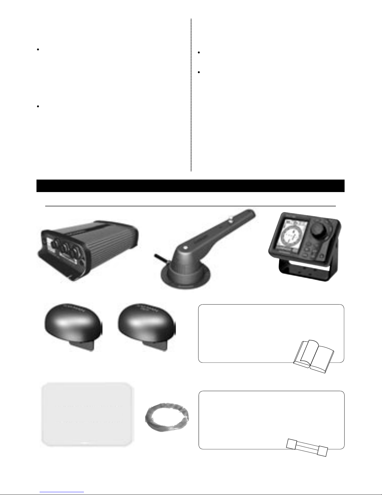
GPS: A GPS or chartplotter, such as a Navman
TRACKER 5000 series chartplotter must be
connected to the G-PILOT 3380 system for
the G-PILOT to operate in GPS mode (see the
G-PILOT 3380 Operation Manual).
Note: GPS must be via NMEA input.
WIND: A wind instrument, such as a
Navman WIND series, must be connected
to the G-PILOT 3380 system for the G-PILOT
to operate in WIND mode (see the G-PILOT
3380 Operation Manual).
SPEED: A speed instrument, such as:
Navman’s SPEED with a paddlewheel
speed sensor
or a GPS or chartplotter, such as
Navman’s TRACKER 5000 or TRACKFISH
6600 series can be connected to the
G-PILOT 3380 system to increase
steering accuracy.
Note: The speed from a paddlewheel sensor
is the speed that the boat is moving through
the water. The speed from a GPS is the speed
over the ground. If there is a water current
then these two speeds will be different. If
the G-PILOT 3380 system is connected to
an instrument with a paddlewheel sensor
and to a GPS, then the G-PILOT 3380 system
will automatically use the speed from the
paddlewheel sensor instrument.
1-2-2 NavBus
NavBus is a Navman proprietary system that
allows systems of multiple instruments to be
built using a single set of transducers. When
instruments are connected by NavBus:
If you change the units, alarms or
calibration in one instrument, then the
values will automatically change in all other
instruments of the same type.
Each instrument can be assigned to a
group of instruments, called a NavBus
group (see NavBus group in the Setup >
Comms menu, in the G-PILOT 3380 Operation
Manual). If you change the backlight in an
instrument in group 1, 2, 3 or 4 then the
backlight will automatically change in the
other instruments in the same group. If
you change the backlight in an instrument
in group 0 then no other instruments are
affected.
If an alarm sounds, mute it on any
instrument which can display that alarm.
For more information, refer to the NavBus
Installation and Operation Manual.
Note: GPS must be via NMEA input.
NavBus and the G-PILOT 3380 system
The G-PILOT 3380 system will automatically
work with additional G-PILOT 3380 displays
or G-PILOT 3100 displays.
The G-PILOT 3380 system can receive wind
data from Navman’s WIND over NavBus.
The G-PILOT 3380 system can receive speed
data from Navman’s SPEED over NavBus.
1-2-3 NMEA
NMEA is an industry standard, but is not as
flexible as NavBus as it requires dedicated
connections between instruments. The
G-PILOT 3380 system has one NMEA input port
and one port that can be configured to be an
input or an output (See G-PILOT 3380 Operation
Manual).
G-PILOT 3380 system NMEA inputs
GPS: The G-PILOT 3380 system can receive
NMEA GPS data from a compatible GPS or
chartplotter, such as Navman’s TRACKER 5000
series chartplotter:
XTE (from APA, APB or XTE sentences) is
required for the G-PILOT 3380 system to
use GPS mode
BRG (from APA sentences) and BOD (from
APA or APB sentences) are optional and
improve performance
COG (from VTG sentences) is optional and
can be displayed.

G-PILOT 3380 System Installation Manual NAVMAN 7
2 G-PILOT 3380 system hardware
MCU600 (Main Control Unit)
Gyro, with 10 m
(33 ft) attached cable
Protective cover for
display unit
G-PILOT 3380 Display unit
Compass, with 10 m
(33 ft) attached cable
WIND: The G-PILOT 3380 system can receive
NMEA wind data from a compatible wind
instrument:
True or apparent wind direction (from
MWV sentences) is required for the G-PILOT
3380 system to use Wind mode.
SPEED: The G-PILOT 3380 system can
receive NMEA speed data from a compatible
paddlewheel or GPS instrument:
SOG (from VTG sentences) is optional and
improves performance.
Note: If the G-PILOT 3380 system is connected
to a Navman series wind or speed instrument
using NavBus, then the G-PILOT 3380 system will
automatically receive and use the wind or speed
data, and the NMEA connection need not be wired.
2 mm (#14) twin
stranded cable for high
current wiring
RFU - Rudder feedback unit
2-1 What comes with your G-PILOT 3380 system
G-PILOT 3380 system NMEA outputs
The NMEA 2 port can be configured to be an
input or to be output:
either heading (HDG & HDT) and rudder
angle (RSA) at once per second
or heading (HDG) at ten times per second
(see NMEA mode in the Setup > Comms menu,
See G-PILOT 3380 Operation Manual).
Documentation
• Warranty
• Display unit mounting template
• This Installation manual
• Operation manual
NAVMAN
Additional hardware
• Mounting hardware
• Cable cover
• Strain relief
• Spare fuses

8 NAVMAN G-PILOT 3380 System Installation Manual
The recommended installation sequence is:
1 Read this manual and the documentation
that comes with the other parts.
2 Plan the installation: select where the
equipment and wiring will be installed (see
section 3-2).
3 Install the MCU600 (see section 3-3).
4 Install the steering drive and wire the heavy
duty and light duty power supplies
(see section 3-4).
5 Install the rudder feedback unit
(see section 3-5).
6 Install the compass (see section 3-6).
3 Installation
3-1 Installation sequence
Warning: Correct installation is critical to the
performance of the unit. It is vital to read this
manual and the documentation that comes
with the other parts before starting installation.
Warning:
The MCU600 is not waterproof. Mount the
unit in a dry place.
The G-PILOT 3380 system display unit is
waterproof.
The compass, gyro and rudder feedback
unit are completely waterproof.
Warning: Ensure that any holes that you
cut will not weaken the boat’s structure. If in
doubt, consult a qualified boat builder.
7 Install the gyro (see section 3-7).
8 Install the display unit and any other
marine instruments that will be used with
the G-PILOT 3380 system (see section 3-8).
9 Carry out the dockside setup
(see section 4).
10 Carry out the sea trials (see section 5).
If you are unsure where a part should be
installed, mount and wire the part temporarily,
without cutting holes in the boat. After the sea
trials have been completed, install and wire
the part permanently.
Power supply: The G-PILOT 3380 system
requires two power supplies, both nominally
12 V DC:
A heavy duty supply for the steering drive
A light duty supply for the G-PILOT 3380
system electronics and display unit; this
supply also powers any additional display
units and other instruments.
The power supplies require one or two
switches and fuses or circuit breakers (see
section 3-4).
Steering drive: The G-PILOT 3380 system can
power a hydraulic pump, constantly running
pump set, hydraulic linear drive or mechanical
drive rated at 12 V DC and up to 20 A.
Rudder linkage: To link rudder to rudder
feedback unit (see section 3-5).
For wiring, see Select Wire Table in section 3-4-2.
External beepers or lights (optional ):
The external output is switched to ground,
30 V DC and 250 mA maximum. If the beepers
and lights require more than 250 mA total, fit
a relay.
Other marine instruments (optional): Wind,
speed or GPS instruments can be connected
(see section 1-2).
Other parts: For systems of several
instruments, wiring and connectors are
required. Navman junction boxes can simplify
wiring several Navman instruments together
(see section 1-2 or the NavBus Installation and
Operation Manual).
Coupling connectors and 10 m (33 ft) extension
cables are available to extend the rudder
feedback unit, compass or gyro cables. Do not
fit more than one extension cable to each unit.
For more information, consult your
Navman dealer.
2-2 Other parts required

G-PILOT 3380 System Installation Manual NAVMAN 9
3-2 Installation guide
This is a general guide for locating and wiring the parts of the G-PILOT 3380 system. The instructions
for a particular part may have additional requirements.
3-2-1 Location guide
Do not mount any part where it can be
used as a handhold, where it will interfere
with the operation of the boat or where it
might be submerged.
Do not mount any part where it will
interfere with launching or retrieving
the boat.
Do not mount any part within 0.5 m (20”)
of the plane of a radar antenna.
Mount the compass and gyro:
At least 1 m (3 ft) away from sources
of electrical signals or noise, such as
the batteries, high-current cables,
other boat cables, engines, fluorescent
lights, power inverters, radio or radar
transmitters and antennas.
At least 1 m (3 ft) away from equipment
containing a magnet, such as a compass
or speaker.
3-2-2 Wiring guide
The G-PILOT 3380 system has two kinds of
cables:
The heavy-duty power supply and steering
drive usually require high-current cables:
Select the wire gauge from the wire size
table (see section 3-4-2).
Fit high-current cables at least 1 m (3 ft)
away from other electronic devices in
the boat.
Keep the cables as short as possible.
Twin 2 mm (#14) cable is supplied with
the G-PILOT 3380 system and can be used
for the high current cable if its gauge is
suitable.
All the other cables are low-current:
Fit low-current cables at least 1 m (3 ft)
away from sources of electrical signals
or noise, such as the high-current cables,
other boat cables, engines, fluorescent
lights, power inverters and radio or radar
transmitters and antennas.
If the cable for the rudder feedback unit,
compass or gyro is too long, do not shorten
the cable; instead coil the cable up near the
main control unit.
The cable for the rudder feedback unit,
compass or gyro can be extended by
adding a 10 m (33 ft) extension cable and
coupling connector. Do not fit more than
one extension cable to each unit.
When fitting any type of cable:
Do not crush, pinch or strain the cable.
Secure the cable at regular intervals.
Ensure no connectors or exposed terminals
are in the bilge.

10 NAVMAN G-PILOT 3380 System Installation Manual
3-3 Installing the MCU600 (Main Control Unit)
Physical
IMPORTANT: 200 mm
(7.87”) clearance required
for cover removal
Installation
Find a suitable location for the unit:
In a dry, cool place; if possible not the engine room.
Close to the high-current power supply and the steering drive, to reduce the length of the high
current wiring.
Accessible for installation and service.
If possible on a vertical panel which does not vibrate.
Follow the location guide (see section 3-2-1).
Mount the unit with the cable connectors at the bottom or to one side, using the screws provided.
Do not mount the unit with the connectors at the top, because dust or moisture might enter the unit.
200 mm (7.87”)
IMPORTANT: 60 mm (2.36”)
clearance required for cables
200 mm (7.87”)
140 mm (5.10”)
60 mm (2.36”)
Screws 90 mm (3.54”) apart
Screw holes 184 mm (7.24”) apart
55 mm
(2.16”)
12
3
1RFU
2Gyro
3Compass /
Heading Sensor

G-PILOT 3380 System Installation Manual NAVMAN 11
3-4 Installing the power supplies and steering drive
3-4-1 Installing the power supplies
The MCU 600 system requires a light duty and a heavy duty power
supply, both 12 V DC.
Note:
Keep all wiring as short as possible.
For the heavy duty supply, use the wire size given in the table
(see section 3-4-2).
Follow the wiring guide (see section 3-2-2).
1 2 3 4 5 6 7 8
Fit strain relief
Connector
cover
Light duty
power
Heavy duty
power
Fuse 1 A
12 V DC power
supply, current to
suit drive
Power supply: one switch configuration
Choose this configuration to have one switch to turn
the G-PILOT 3380 system and any other instruments
on and off.
Circuit breaker or fuse and
switch, current rating to suit
steering drive
Power supply: two switch configuration
Choose this configuration to be able to turn the drive
power off and leave other instruments powered.
Fit strain relief
Connector
cover
Switch
Heavy duty
power
Fuse 1 A
Light duty
power
Note: If powering more than three extra display units or other series instruments, fit another switch and
fuse for the light duty power supply for these extra instruments
12 V DC power
supply, current to
suit drive
Circuit breaker or
fuse and switch,
current rating to suit
steering drive
MCU600
1 2 3 4 5 6 7 8

12 NAVMAN G-PILOT 3380 System Installation Manual
3-4-2 Installing the steering drive
Install the steering drive according to one of the diagrams on the following pages.
Note
Keep all wiring as short as possible.
Use the wire size given in the table below.
Follow the wiring guide (see section 3-2-2).
Wire less than #10 gauge will not fit directly into the four way terminal block. Fit ferrules or reterminate
the wire with #10 gauge wire.
If more than one wire is to be fitted to a terminal of the four way terminal block, join the wires together
in a suitable way.
Wire size table
To choose a wire gauge for an installation:
1 Measure the length of twin cable required, i.e. the distance from the main control unit to the heavy
duty power supply or to the drive.
2 Choose the column with the cable length and the row with the circuit current. The intersection
of the row and column gives the preferred (minimum) cable wire gauge for less than 3% voltage
drop in a 12 V system.
Cable length (from main control unit to power supply or to drive)
2.5 ft
0.7 m
5 ft
1.5 m
7.5 ft
2.2 m
10 ft
3 m
12.5 ft
3.7 m
15 ft
4.5 m
17.5 ft
5.2 m
20 ft
6 m
Current
1 amp #18
0.75 mm
#18
0.75 mm
#18
0.75 mm
#18
0.75 mm
#18
0.75 mm
#18
0.75 mm
#18
0.75 mm
#18
0.75 mm
2 amp #18
0.75 mm
#18
0.75 mm
#18
0.75 mm
#18
0.75 mm
#18
0.75 mm
#16
1.5 mm
#16
1.5 mm
#16
1.5 mm
3 amp #18
0.75 mm
#18
0.75 mm
#18
0.75 mm
#16
1.5 mm
#16
1.5 mm
#16
1.5 mm
#14
2.5 mm
#14
2.5 mm
4 amp #18
0.75 mm
#18
0.75 mm
#16
1.5 mm
#16
1.5 mm
#14
2.5 mm
#14
2.5 mm
#14
2.5 mm
#12
4 mm
5 amp #18
0.75 mm
#16
1.5 mm
#16
1.5 mm
#14
2.5 mm
#14
2.5 mm
#12
4 mm
#12
4 mm
#12
4 mm
6 amp #18
0.75 mm
#16
1.5 mm
#16
1.5 mm
#14
2.5 mm
#12
4 mm
#12
4 mm
#12
4 mm
#10
6 mm
7 amp #18
0.75 mm
#16
1.5 mm
#14
2.5 mm
#14
2.5 mm
#12
4 mm
#12
4 mm
#10
6 mm
#10
6 mm
8 amp #18
0.75 mm
#16
1.5 mm
#14
2.5 mm
#12
4 mm
#12
4 mm
#10
6 mm
#10
6 mm
#10
6 mm
9 amp #18
0.75 mm
#16
1.5 mm
#14
2.5 mm
#12
4 mm
#12
4 mm
#10
6 mm
#10
6 mm
#10
6 mm
10 amp #18
0.75 mm
#14
2.5 mm
#12
4 mm
#12
4 mm
#10
6 mm
#10
6 mm
#10
6 mm
#8
10 mm
15 amp #16
1.5 mm
#12
4 mm
#12
4 mm
#10
6 mm
#10
6 mm
#8
10 mm
#8
10 mm
#6
16 mm
20 amp #14
2.5 mm
#12
4 mm
#10
6 mm
#8
10 mm
#8
10 mm
#6
16 mm
#6
16 mm
#6
16 mm

G-PILOT 3380 System Installation Manual NAVMAN 13
Fit strain relief
Wiring polarity does
not matter.
Motor
MCU600
Example of hydraulic steering with hydraulic help pump.
In the Setup > Vessel menu (See G-PILOT 3380 Operation Manual), set Drive Type to Motor.
Example of mechanical steered power vessels with hydraulic linear drive for sailing boat
In the Setup > Vessel menu (See G-PILOT 3380 Operation Manual), set Drive Type to Motor.
Motor
Clutch
relay
coil
1N4002 diode or equivalent
Fit close to relay coil
Connector cover
No connection
MCU600
Heavy duty power (see
section 3-4-1)
Fit strain relief
Wiring polarity does
not matter.
Heavy duty power (see
section 3-4-1)
Note: Clutch relay coil must draw
less than 300mA

14 NAVMAN G-PILOT 3380 System Installation Manual
Installing a electric drive motor with clutch relay
In the Setup > Vessel menu (See G-PILOT 3380 system Operation Manual), set Drive Type to Motor.
Installing a continuous running pump and solenoid valves.
In the Setup > Vessel menu (See G-PILOT 3380 system Operation Manual), set Drive Type to Spool ground.
Fit strain relief
Wiring polarity does
not matter.
Motor
MCU600
Clutch
coil
1N4002 diode or equivalent. Fit
close to relay coil
1N4002 diode or equivalent
Fit close to relay coil
Relay coil
MCU600
1N4002 diode or equivalent
Fit close to relay coil
Relay contacts
Relay coil
Starboard
Port
Motor
Fit strain relief
Heavy duty power (see section 3-4-1)
Wiring polarity does
not matter.
Note: Motor is not
required for engine PTO
systems.
Relay contacts
Note: Relay is required if the clutch
circuit is greater than 300 mA.
Note: Relay is required if the
clutch circuit is greater than
300 mA.
Connector cover
Connector cover

G-PILOT 3380 System Installation Manual NAVMAN 15
Installing solenoid valves or relays with jog or electric steering
In the Setup > Vessel menu (See G-PILOT 3380 Operation Manual), set Drive Type to Spool ground.
MCU600
Starboard
Port
Fit strain relief
No connection
Jog/steer controls
Heavy duty power (see
section 3-4-1)

16 NAVMAN G-PILOT 3380 System Installation Manual
3-5 Installing the RFU (rudder feedback unit)
Physical
10 m (33 ft) cable
Arm
90 mm
(3.5”)
220 mm
(8.7”)
Base
Linkage to
rudder
Rudder
shaft
Arm rotates freely
around base.
LT8 connector
These two
distances to
be equal.
Connecting rod, with quick
release fittings and lock
nuts each end
End of connecting rod
snaps into one of the
holes on the arm.
Mounting requirements
These two
distances to
be equal.
Base to be adjacent to
rudder shaft so that this
angle is 90°
Rudder shaft to be
parallel to shaft in
base.
Rudder linkage and
arm to move in the
same plane
Note
The unit is completely waterproof but should not be immersed.
Mount the unit on a panel which does not vibrate.
Follow the location guide (see section 3-2-1).
Adjust position of rod on
arm if required.
Cut connecting rod
if required. Thread = M5

G-PILOT 3380 System Installation Manual NAVMAN 17
Alignment
The arm can rotate freely around the base. When the rudder is amidships, the arrow on the arm must
point to one of the centre lines on the base.
Centre line
Therefore in an installation, the base can be rotated to two positions. We recommend the position that
has the cable on the opposite side to the connecting rod.
Centre line
Sets of lines
show the two linear
ranges of the unit.
Base
Recommended
(rudder amidships).
Arrangements
Recommended: U-shaped arrangement with the arm parallel to the length of boat:
Satisfactory: U-shaped arrangement
with arm not parallel to length of boat, for
example:
Not recommended: Z-shaped arrangement,
for example:
If rudder turns too far, the unit might not return to the
Z shape.
Bow of
boat
Bow of
boat
Not recommended, cable can
foul rudder linkage.

18 NAVMAN G-PILOT 3380 System Installation Manual
Installation
1 Find a suitable location and arrangement for the unit as described above.
2 Choose, assemble and fit a suitable rudder linkage.
3 Fit the unit as shown below:
If necessary, mount
base on block to set
height.
Set rudder
amidships.
Rotate base so arrow on arm
points near centre line on base.
Fit two screws provided loosely
in middle of slots.
Rotate base so arrow on arm
points to centre line on base.
Fit third screw provided,
tighten all screws.
Join coupling to
rudder linkage. Snap end into
correct hole in arm.
Ensure rudder is
amidships.
If necessary, cut connecting
rod at this end, then replace
coupling and lock nut.
4 Wire the cable back to the MCU600, following the wiring guide (see section 3-2-2).
MCU600
Plug connector into the RFU socket
Holes in the bulkheads must
be at least 18.5 mm (0.73”)
diameter.

G-PILOT 3380 System Installation Manual NAVMAN 19
3-6 Installing the Compass
Physical 101 mm, (4”)
Mounting holes
for screws
97 mm, (3.8”)
71 mm, (2.8”)
10 m (32.8 ft)
LT8 connector
Location
Mount the compass:
At least 1 m (3 ft) away from any steel or
iron boat part, such as:
a steel hull, deck, cabin or steel
reinforcing in ferro-cement hulls
steel equipment such as motors and
cooking equipment
places where steel objects are stored,
such as the anchor locker and storage
lockers
At least 2 m (6 ft) away from equipment with
a magnet and equipment which generates
electromagnetic fields, such as a compass,
a battery, high current wiring, an electric
motor and a radio or radar transmitter
or antenna.
As close as possible to the centre of move-
ment of the boat, to minimise how much the
compass moves when the boat rocks and
pitches. If the compass can not be mounted
at the centre of movement, it is usually best
to mount the compass as low as possible.
On a vertical panel which does not vibrate.
The unit is completely waterproof but should
not be immersed. The compass is not affected
by other metals, such as stainless steel, copper
or brass. Follow the location guide (see section
3-2-1).
Fibreglass or wood hull and cabin: mount compass at the centre of movement (for planing hulls, the
centre of movement is usually close to the stern):
Steel hull, non-steel cabin: mount compass
1 m, (3 ft) above hull:
Steel hull and steel cabin: mount compass on
a pole 1 m (3 ft) above the hull and at least 1 m
(3 ft) from the cabin:
At least 1 m (3 ft)
1 m (3 ft)
1 m (3 ft)

20 NAVMAN G-PILOT 3380 System Installation Manual
Installation
1 Find a suitable location for the unit as described above.
2 Mount the unit with the three screws provided. Use a level to ensure the unit is vertical to
within 10°.
Less than
10° 10°
3 Wire the cable back to the MCU600, following the wiring guide (see section 3-2-2).
Less than 10° 10°
MCU600
Plug connector into the Compass/HS socket
Holes in the bulkheads
must be at least 18.5 mm
(0.73 in) diameter.
Note
If you move the compass with respect to the gyro while the power is on, wait for the heading to stabilize.

G-PILOT 3380 System Installation Manual NAVMAN 21
3-7 Installing the Gyro
Physical
Mounting holes
for screws
LT8 connector
Location
Mount the gyro as close as possible to the centre of movement of the boat, to minimize how much
the gyro moves when the boat rocks and pitches.
Mount the gyro on a panel which does not vibrate.
The unit is completely waterproof but should not be immersed. Follow the location guide (see
section 3-2-1).
The Ideal location is at the centre of movement (for planing hulls, the centre of movement is usually
close to the stern).
101 mm, (4”)
97 mm, (3.8”)
71 mm, (2.8”)
10 m (32.8 ft)
Other manuals for G-PILOT 3380
1
Table of contents
Other Navman Autopilot System manuals