Nayar Systems BVA User manual

BVA
1 — Last update: Jul 18, 2022
Nayar Systems
Copyright © 2022 Nayar Systems

Table of Contents
1. Manufacturer note ............................................................................................................................. 1
2. Device description............................................................................................................................. 2
2.1. Status indicator LEDs................................................................................................................. 4
2.2. Device front panel ...................................................................................................................... 5
2.3. Device rear panel ....................................................................................................................... 6
3. Configuration, installation and start-up ........................................................................................... 7
3.1. Installation of BVA...................................................................................................................... 8
3.1.1. Installation of BVA 12 relays at lift car/s ............................................................................. 9
3.1.2. Installation of BVA 2 relays at lift stops ............................................................................ 11
3.2. Configuration............................................................................................................................ 13
3.2.1. Account Management ...................................................................................................... 14
3.2.2. Creating new installation and adding BVA devices ........................................................... 18
3.2.3. Lift car/s configuration (BVA 12 relays) ............................................................................ 23
3.2.4. Lift stop/s configuration (BVA 2 relays) ............................................................................ 25
3.3. Use of Accessible Virtual eypad (BVA)................................................................................... 27
4. Technical support............................................................................................................................ 28
5. Troubleshooting .............................................................................................................................. 29

1. Manufacturer note
This manual describes good practices recommended by Nayar Systems S.L., in order to ensure an
optimal performance in safe conditions. Any improper manipulation, damage caused during the
installation of the device and, in general, an incorrect use not explained in this document may void the
warranty.
The device must be manipulated only by qualified and skilled professionals with specific technical
knowledge to avoid a failure of the device due to inappropriate manipulation.
Nayar Systems S.L. is not responsible for damage as a result of ignoring the indications and
recommendations included in this manual
The device must not be wet nor installed in humid places.
Optimal working temperatures are between -20ºC and 70ºC
*
Nayar Systems BVA - 1_en
Page 1 of 29
2. Device description
The Accessible Virtual Keypad product (also known as BVA) is mainly designed to remotely activate
buttons on the lift car operating panel through a Smartphone, avoiding its physical manipulation.
Moreover, BVA helps universal accessibility of the lift through its App. The device can work with or
without Internet connectivity. There are two versions of this product depending on the number of relays:
BVA 12 relays and BVA 2 relays. BVA 12 relays is designed to be connected on buttons on lift car and
BVA 2 relays, rear external buttons at each floor, even though both products may be swapped.
Electrical characteristics
DC-DC converter:
• Operating range: 7 – 50VDC
• Consumption: 70mA@20VDC
BVA:
• Operating range: 5VDC
• Consumption: 141mA@5VDC
Inside the box
• BVA
• Quick start guide
• DC-DC converter
• Pluggable Terminal Block 10 positions (only on BVA 12 relays)
Nayar Systems BVA - 1_en
Page 2 of 29

• Pluggable Terminal Block 4 positions
• Wall bracket
• DIN RAIL Mounting clip
• 2x Screw
Technical specs and connections
• Internal PCB Antenna
• Wi-Fi: 2.4GHz, 802.11 b/g/n
• Wireless connection by proximity (radio link 2.4GHz)
• 2x Relay connections (BVA 2 relays)
• 12x Relay connections (BVA 12 relays)
• Type of contact: Normally open (NO)
• Maximum output current charge: 2A
• Maximum switching Voltage: 220 VDC, 250 VAC
• Operating range: -20 ~ 70ºC
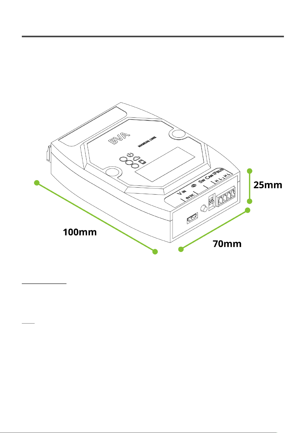
• Dimensions (without complements): 100 × 70 × 25 mm
In order to install BVA devices, it is compulsory to check compatibility by consulting manufacturers
device note and installation manual. Buttons or contacts must allow activation by a relay.
Nayar Systems BVA - 1_en
Page 3 of 29

2.1. Status indicator LEDs
The BVA devices has three LEDs to indicate its status:
–Power LED
It shows whether the device is powered ON or OFF.
• Device powered OFF –
• Device powered ON –
–Internet connectivity LED
It shows whether the device has Internet connectivity. Internet connectivity is only required when
configuring the BVA.
• Device without Internet connectivity –
• Device with Internet connectivity –
–Active local connection LED
It shows whether the device is wireless connected to a smartphone by proximity (radio link of 2.4
GHz).
• Device without local connection –
• Device with local connection –
Nayar Systems BVA - 1_en
Page 4 of 29

2.2. Device front panel
At the front panel of the device can be found the following information:
MicroUSB – VIN
Input for the power supply. So as to provide an input voltage of 5VDC through a microUSB connector, a
DC-DC converter with the input range 7 – 50VDC is supplied.
Discover button
This button carries out two actions:
•Linking the device to the App: This action is fully explained on 3.- Configuration, installation and
start-up.
•Linking to a Wi-Fi network created by another Nayar Systems device: For example, if there is
a Nayar Switch installed, it is possible to connect to its Wi-Fi network, by pressing the Nayar
Switch Discover button and then, the one of BVA.
SW
Two microswitches with the following functionalities:
1 Activation / deactivation of CAN terminating resistors
2 Activation / deactivation of IPBus terminating resistors
CAN ( * ) / IPBus ( * )
•CAN H and L: Reception of CAN frames from lift controller
•IPBus H y L: Processing IPBus frames to transmit data through two electrical wires.
(*) On current product versions, these functionalities are not available.
Nayar Systems BVA - 1_en
Page 5 of 29

2.3. Device rear panel
Rear panel distribution is different depending on the versions of the product chosen:
BVA 2 relays
4 position connector
4 position connector, including 2 relay connections (relay 1 and 2) and two independent common
contacts.
BVA 12 relays
4 position connector
4 position connector, including 2 relay connections (relay 1 and 2) and two independent common
contacts (COM1 and COM2). In such a way that COM1 contact corresponds to relay 1 and COM2, to
relay 2.
10 position connector
10 position connector, which corresponds to relay connections (from relay 3 to 12). These connections
share the same common contact COM2.
Nayar Systems BVA - 1_en
Page 6 of 29

3. Configuration, installation and start-up
A complete installation with BVA devices requires the following elements:
• 1 Device per cabin: BVA 12 relays
• 1 Device per floor (compatible with 1 or 2 buttons): BVA 2 relays
In the following example the installation consists of 1 cabin and 3 floors, so the following elements are
required:
• 1x BVA 12 relays
• 3x BVA 2 relays
Hereinafter, the procedure to optimally install BVA devices is described.
Nayar Systems BVA - 1_en
Page 7 of 29

3.1. Installation of BVA
Installation of BVA devices must be implemented near buttons, to make its installation easier and to
have good access to connectors from both sides. Moreover, it is highly recommended the installation of
the devices at half of the height of the floor, in order to avoid any interference with any devices located
at upper and/or lower floors.
Furthermore, switching off the power supply of the facility is recommended to be sure that the working
environment is safe.
It may be necessary to disassemble the lift car operating panel or external buttons for accessing at its
rear part, where the BVA device will be installed, in a way that the device will not be accessible by the
user of the lift.
Recommended material
• Wire diameter: 28 – 16 AWG (0.5 – 1.5mm²)
• Ties (Optional)
• Screwdriver for screws of 5.3mm diameter head
• Drill with a 6mm diameter bit
• 6mm plastic straddling dowel
Nayar Systems BVA - 1_en
Page 8 of 29
Table of contents


