Potter RA-7690 Assembly instructions

RA-7690
LCD ANNUNCIATOR
INSTALLATION SHEET
MKT. #5406017 - REV A
LT-0263-P7/03
PRINTED IN USA
PotterElectricSignalCompany • 2081CraigRoad,St.Louis,MO,63146-4161•Phone:800-325-3936/Canada888-882-1833•www.pottersignal.com
DESCRIPTION
The RA-7690 LCD Annunciator provides three 2-button
Panic keys, an AC power LED, 32-character display,
backlit keyboard with easy-to-read lettering, and a built-
in speaker.
INSTALLINGTHEKEYPAD
The keypad housing is made up of two parts: the
front
, which
contains the circuit board and other components, and the
base
. To mount the keypad, remove the base from the front
by inserting a flat screwdriver into one of the openings on the
bottom. Twist the screwdriver while pulling the halves apart.
Repeat with the other opening.
The RA-7690 uses the same plastic housing and are de-
signed to easily install on any 4-square box, 3-gang switch
box, or flat surface. Figure 1 shows the mounting hole
locations on the base of the keypad housing.
PAGE 1 OF 4
WIRINGTHEKEYPADUSINGTHEWIRINGHARNESS
The RA-7690 keypad is supplied with a
4-wire harness for connection to the panel's keypad bus.
Observe the wire colors when connecting the red, yellow,
green, and black wires to the keypad bus. When wiring
directly to the panel terminals, connect the red wire the
terminal 7, the yellow to terminal 8, green to 9, and the black
wire the terminal 10.
Guide Tabs
Reference Card
Back of 692
Keypad Base
Surface and Backbox
Mountin
g
Holes
Combined 4-square
and 3-gang s itch box
Mounting Holes
Surface and Backbox
Mounting Holes
Surface and Backbox
Mounting Holes
Red - 7
Yellow - 8
Green - 9
Black - 10
Figure 1: Back of RA-7692 Keypad
Back of RA-7692
Keypad Base

RA-7690
LCD ANNUNCIATOR
INSTALLATION SHEET
MKT. #5406017 - REV A
LT-0263-P7/03
PRINTED IN USA PAGE 2 OF 4
END-USEROPTIONS
The RA-7690 keypads provide three adjustments to the
keypad that can be made by the end-user. Below is a
description of the options and instructions on their operation.
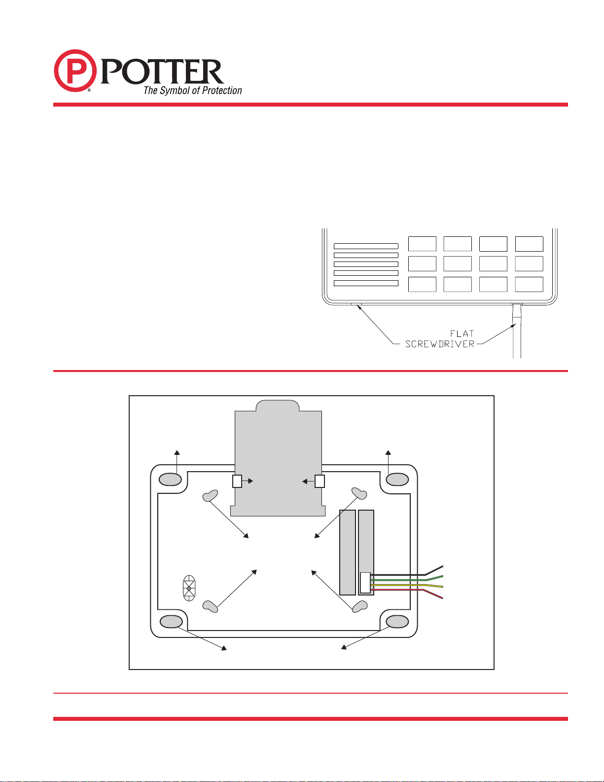
To access the User Options portion of the keypad, press and
hold the Back Arrow and COMMAND keys for two seconds.
The keypad display changes to SET BRIGHTNESS. Press the
COMMAND key to display the next option or the Back Arrow key
to exit the User Options function.
BacklightingBrightness
This option allows the user to set the brightness level of the
keypad's Liquid Crystal Display (LCD), AC LED, and the
Greenkeyboard backlighting. Atthe SETBRIGHTNESS
display, use the left Select key to lower the keypad brightness.
Use the right Select key to increase the brightness.
Note: If the brightness level is lowered, it temporarily reverts
back to maximum intensity whenever a key is pressed. If no
keys have been pressed, and the speaker has not sounded
for 30 seconds, the selected brightness is restored.
Internal Speaker Tone
This option allows the user to set the tone of the keypad's
internal speaker. At the SET TONE display, use the top left
Select key to make the tone lower. Use the right Select key to
make the tone higher.
Volume level
This option allows the user to set the volume level of the
keypad's internal speaker for key presses and prewarn
conditions. During alarm, trouble, and prewarn conditions,
the volume is always at maximum level. At SET VOLUME
LEVEL, use the left Select key to lower the keypad volume.
Use the right Select key to raise the volume.
USINGTHEKEYPADFUNCTIONS
KeyboardBacklighting
The keyboard backlighting on the RA-7690 turns on every time a key is pressed or the speaker sounds. During an alarm
condition, the keyboard illuminates in Red to visually alert people on the site. The Red backlighting turns off when the Sensor
Reset function is used. The keyboard backlighting dims to medium brightness whenever the speaker is on.
Model Number
The keypad's model number and firmware version and date
are displayed, but cannot be changed by the user.
KeypadAddress
The keypad's current address is displayed, but cannot be
changed by the user. Press the Back Arrow key to exit the
User Options function.
SilencingSystem
The default User Code is 99 Command. When the panel is in
alarm, enter the User Code followed by Command and the
internal buzzer (and notification circuit in the PFC-7501) will
silence. The keypad will remain illuminated while the panel is
in alarm.
ResettingPanel
When the panel is reset it momentarily removes power from
the sensors. The display will show SENSORS OFF followed
by SENSORS ON, then the programmed normal message
will be displayed and the keypad will return to normal back-
lighting.
The panel must be silenced before it can be reset. To reset
the panel, press the COMMAND button. The display will read
MENU? NO YES press the far right key under yes. The panel
will prompt the user to enter the User Code (99 is default).
After entering the User Code press the COMMAND Key. The
panel will display SENSOR RESET. Press any of the top row
keys and the sensors and panel will be reset.
WIRINGSPECIFICATIONS
1. You can install individual keypads on wire runs of up to
500 feet using 22-gauge wire or up to 1,000 feet using
18-gauge wire. To increase the wire length or add
additional devices, a power supply is required.
2. Maximum distance for any one keypad bus circuit
(length of wire) is 2,500 feet regardless of the gauge of
wire. This distance can be in the form of one long wire
run or multiple branches with all wiring totaling no more
than 2,500 feet.
3. Maximum number of devices per 2,500 feet circuit is 4.
4. Maximum voltage drop between the panel (or auxiliary
power supply) and any device is 2.0 VDC. If the voltage
at any device is less than the required level, an auxiliary
power supply should be added at the end of the circuit.
The 2.0 VDC drop minimum has not been verified by
UL.

RA-7690
LCD ANNUNCIATOR
INSTALLATION SHEET
MKT. #5406017 - REV A
LT-0263-P7/03
PRINTED IN USA PAGE 3 OF 4
INSTALLEROPTIONS:KEYPADOPTIONSAND
DIAGNOSTICS
The Ra-7690 Annunciator also contains Keypad Options and
Keypad Diagnostics programs that allows you to configure
and test the keypad operation.
You can only access the Installer Options function through
the User Options function. After holding down the Back Arrow
and COMMAND keys for two seconds and getting the SET
BRIGHTNESS display, enter the code 3577 (INST) and press
COMMAND. The display now changes to KPD OPT (keypad
options) KPD DIAG (keypad diagnostics) and STOP.
KEYPADOPTIONS(KPDOPT)
This option allows you to set the keypad address, select
supervised or unsupervised mode, and change the keypad
display message. To enter, press the left Select key under
KPDOPT. ThedisplaychangestoCURRENTKEYPAD
ADDRESS: ##.
Setting the Keypad Address
You can set the keypad address from 01 to 16. The factory
default address is set at 01. To change the current address,
press any Select key to delete the old address and then press
the appropriate number keys on the keyboard. It is not
necessary to enter a leading zero for addresses 01 to 09.
Selecting Supervised or Unsupervised Mode
You can configure the keypad for either supervised or unsu-
pervised operation. Keypads that have zones connected to
them must be supervised. Supervised keypads cannot share
addresses with other keypads.
To enhance the supervision feature, assign an output to the
Device Fail Output in the panel’s programming and connect a
device to the corresponding output that will trip when the
keypad fails. This provides notification at the central station
and the site. The other keypads will not display the device fail.
Note: The Device Fail Output
cannot
be used if there are
any
unsupervised devices
on the system.
Unsupervised keypads
can
operate with other unsupervised
keypads sharing the same address. Zones cannot be used
on unsupervised keypads. To change the current setting,
press the Select key under SUP or UNSUP. An asterisk
appears next to the selected option.
Entering the Default Keypad Message
You can enter a custom message of up to 16 characters that
appears on the top line of the keypad display whenever that
line is not being used for any other purpose. Press any Select
key to clear the current display and use the data entry keys to
enter a new custom display.
Entering Alpha Characters
You can use the keypad to enter alpha characters. To enter
an alpha character, press the key that has the desired letter
written below it. The keypad display will show the number on
that key. To change the number to a letter, press the top row
Select key that corresponds to the location of the letter under
the key. For example, if you press key number 1, the letters for
that key are A, B, and C. Press the first Select key for A, the
second for B, and the third for C. See Figure 3.
EnteringNon-Alphanumeric Characters
When in the Installer Options Menu, each key also has a
special, non-alpha character you may use. These characters
are not shown on the keypad, but they can be selected by
following the key map in Figure 4. Enter a space by pressing
9 then the third Select key. The special characters available
are as follows starting with the 1 digit key to the 9 digit key: ( ) !
? / & $ ‚ ’ and - . * # for the 0 key.
ABC(
First Letter Second Letter Third Letter Special Character
Figure3:EnteringAlphaCharacters
12 34
56 78
90 COMMAND
Figure4:LettersandCharactersKeyMap
ABC( DEF ) GHI! JKL ?
MNO/ PQR & STU $ VWX,
YZ(SPACE)' - . * #

RA-7690
LCD ANNUNCIATOR
INSTALLATION SHEET
MKT. #5406017 - REV A
LT-0263-P7/03
PRINTED IN USA
SPECIFICATIONS
Operating Voltage: 8.0 to 16 VDC.
Current Draw: RA-7690 100mA standby and alarm
Dimensions: 6.75"Wx 5"Hx 1"D
Compatible Panels: PFC-7500 Series
KEYPADDIAGNOSTICS(KPDDIAG)
This option allows you to:
•check the display segments
•check the keyboard backlighting
•testindividual keys
Press the Select key under KPD DIAG.The keypad lights all segments of the display and illuminates the keyboard in
Green. A few seconds later the keypad turns off the display and illuminates the keyboard in Red. The keypad then
alternatesbetween these two states for approximately two minutes.
Press COMMAND at any time to continue. The display changes to PRESS KEY TO TEST. This option allows you to
test each key on the keyboard to ensure it's operating properly. Press and hold each key for about two seconds. The
number of the key being held appears in the display. Verify it is the correct number before testing the next key.
Exiting the Installer Options
When done, press the COMMAND key once to return to the Installer Options screen. Press the Select key under STOP
to exit the Installer Options function.
PAGE 4 OF 4