NBE Brawn mixer BTO Series User manual

OPERATION
AND
MAINTENANCE
MANUAL
SERIAL NUMBER
___________________
CUSTOMER:____________________________
SALES REP.:____________________________
BTO SERIES

– THIS PAGE IS INTENTIONALLY LEFT BLANK –

ROTATION
PER
ORDER
D
F MAX.
A
E
B
C
10°
NEMA C-FACE MOTOR
FLEXIBLY COUPLED FOR
SHOCK LOADING PROTECTION.
LIFTING EYE
OPTIONAL UPPER
IMPELLER
IMPELLER SPACING
ADJUSTABLE W/KEYWAY
LOWER A35 IMPELLER
DIAMETER PER ORDER.
OTHER STYLES OPTIONALLY
AVAILABLE.
STANDARD TEFC ELECTRIC MOTOR.
MOTOR OPTIONS INCLUDE:
INVERTER RATED, EXPLOSION-PROOF
AND MILL & CHEMICAL DUTY.
SHAFT LENGTH AND
DIAMETER PER ORDER.
OPTIONAL
AF3 IMPELLER
ALL DIMENSIONS ARE IN INCHES.
*FOR REFERENCE ONLY*
NOTE:
1. BASIC WEIGHT DOES NOT INCLUDE
SHAFT, IMPELLER(S) OR MOTOR.
2018
DATE:
©
DIMENSION AND ASSEMBLY DRAWING
APPROVED BY:
9/13/2018
BTO
TK0099M
12838 STAINLESS DR
HOLLAND, MI 49424
PH: 616-399-5600
FAX: 616-399-3084
DATE:
DRAWN BY:
MIXER MODEL
B-
DWG.
NO.
REV.
* ALL DIMENSIONS AND WEIGHTS ARE FOR REFERENCE ONLY
UNLESS THE DRAWING IS CERTIFIED.
* ALL EQUIPMENT DESIGN AND APPLICATION DATA SHOWN
HEREIN IS CONFIDENTIAL AND THE PROPERTY OF BRAWN MIXER.
NO USE OR DISCLOSURE THEREOF MAY BE MADE WITHOUT OUR
WRITTEN PERMISSION.
BSB
ANGLE RISER MOUNTED MIXER


4
5
7
1
6
3
2
*FOR REFERENCE ONLY*
4
ALTERNATE CONST.
OF SHAFT
MIXER SHAFT ASSEMBLY
1. ATTACH THE SHAFT COLLAR (ITEM 5)
TO THE MIXER SHAFT (ITEM 4).
2. PLACE THE KEY (ITEM 7) ON THE
MIXER SHAFT AND SLIDE THE MIXER
SHAFT INTO THE HOLLOW OUTPUT
SHAFT ON THE GEARDRIVE (ITEM 1).
3. PLACE THE THRUST WASHER (ITEM
6) OVER THE HOLLOW OUTPUT SHAFT
ON THE TOP OF THE GEARDRIVE.
APPLY THREADLOCKER TO THE
THREADS OF THE HEX HEAD CAP
SCREW (ITEM 3), INSTALL IT THRU THE
THRUST WASHER AND INTO THE MIXER
SHAFT. TORQUE THE GRADE 5 HEX
HEAD CAP SCREW TO THE
RECOMMENDED VALUE IN THE O&M
MANUAL.
4. ATTACH THE GUARD (ITEM 2) ON THE
TOP OF THE GEARDRIVE.
* QUANTITY VARIES DEPENDING
ON SHAFT DESIGN.
BSB
* ALL DIMENSIONS AND WEIGHTS ARE FOR REFERENCE ONLY
UNLESS THE DRAWING IS CERTIFIED.
* ALL EQUIPMENT DESIGN AND APPLICATION DATA SHOWN
HEREIN IS CONFIDENTIAL AND THE PROPERTY OF BRAWN MIXER.
NO USE OR DISCLOSURE THEREOF MAY BE MADE WITHOUT OUR
WRITTEN PERMISSION.
REV.
DWG.
NO.
A-
MIXER MODEL
DRAWN BY:
DATE:
12838 Stainless Drive
Holland, MI 49424
PH: 616-399-5600
FAX: 616-399-3084
TK0145
BTO SHAFT ASSEMBLY
10/29/2018
APPROVED BY:
DIMENSION AND ASSEMBLY DRAWING
©
DATE:
2018


BTO-SERIES OPERATION & MAINTENANCE MANUAL
12838 Stainless Drive, Holland, MI 49424 Phone: 616/399-5600 Fax 616/399-3084
Copyright 2018 BRAWN Mixer www.BRAWNMIXER.com Page 1 of 9
11/27/2018
CONTENTS
Mixer Installation / Assembly / Dimension Drawings
Safety ............................................................................ 1
Customer Service Contact ............................................ 2
Initial Inspection............................................................. 2
Installation ..................................................................2-3
Shaft and Impeller Assembly.........................................3
Start-Up......................................................................3-4
Electric Motors............................................................4-6
Maintenance / Lubrication ..........................................6-8
Storage.......................................................................... 8
Warranty........................................................................ 9
SAFETY
The precautions mentioned in this manual are not
intended to cover all hazards that may exist in a plant or
on this equipment. Using safety mechanisms require the
constant attention of everyone in the vicinity of this (or
any) equipment.
A plant and the related equipment are only as safe as the
personnel are safety-minded. Proper equipment
maintenance and the use of personal safety devices will
contribute as much toward safety as will any number of
mechanical safety devices.
WARNING
To assure maximum safety, optimum performance,
and to gain knowledge of the product, it is essential
that you or any other operator of this equipment read
and understand the contents of this manual before
the mixer is operated.
Installation, operation and maintenance must be
performed only by qualified personnel.
Do not operate this equipment unless all safety
devices are installed and working properly. Check
all devices prior to starting the equipment.
Disconnect and lock out electrical power before
installing or servicing the mixer.
Do not touch rotating parts (keep all guards and
safety devices installed while operating).
Develop a safety checklist for this equipment and
perform regular maintenance to ensure continued
and proper operation.
Do not make any field changes or modifications
without reviewing the change with your BRAWN
sales representative or the BRAWN Customer
Service Department.
CUSTOMER SERVICE
Mixer Model #.............................................BTO-SERIES
Mixer Serial #_________________________________
Contact:
Customer Service............................... 616/399-5600
E-Mail .................................sales@brawnmixer.com
BTO SERIES MIXERS
BRAWN NAMEPLATE

BTO-SERIES OPERATION & MAINTENANCE MANUAL
12838 Stainless Drive, Holland, MI 49424 Phone: 616/399-5600 Fax 616/399-3084
Copyright 2018 BRAWN Mixer www.BRAWNMIXER.com Page 2 of 9
11/27/2018
CUSTOMER SERVICE, Cont.
You have received a quality engineered and
manufactured BRAWN mixer. We value your business,
and we will strive to provide you with the proper service
and equipment to meet your needs.
The information contained in this BRAWN Mixer
Operator's Manual is designed to assist you in putting
your BRAWN mixer into operation without further delay.
Please read the entire manual before attempting to
start your mixer. If you have any further questions or if,
by some chance, there are some missing components,
contact your BRAWN Mixer Representative or the factory
immediately.
We welcome your comments and suggestions
concerning any BRAWN Mixer product. Please direct
these comments in writing to the National Sales Manager
at BRAWN Mixer, located in Holland, Michigan. To
expedite troubleshooting service, please make your initial
contact through your BRAWN Mixer Representative. If,
for whatever reason, your representative cannot be
reached and you have an emergency condition, please
call us directly at 616/399-5600 and ask for the
Customer Service Department.
Remember, you are backed by your BRAWN Mixer
Technical Representative and the factory support team.
We are here to assist you; let us know how we can be of
help.
INITIAL INSPECTION
1. Upon receipt of your Brawn mixer, check for possible
shipping damage. Report any damage immediately
to the carrier and to Brawn Mixer.
2. All Brawn mixers are shipped with the shaft and
impeller(s) disassembled from the drive assembly.
In addition, the clamp or cup mount and any
mounting hardware for portable mixers are shipped
loose.
3. Storage: Mixers should not be stored near vibrating
machinery to avoid damage to the bearings. Store
mixers as packaged by the factory. For longer
storage periods, consult factory. If electric motors
have been subjected to humid conditions, check the
insulation resistance between phase and mass and
between the different phases. The resistance should
not be less than 100 megohms. If the resistance is
less, please consult the factory. If mixer is stored for
more than a year, the condition of the gear lubricant
should be checked before the mixer is put in
operation (see lubrication instructions).
INSTALLATION
[REFER TO ASSEMBLY / DIMENSION DRAWING]
Refer to the mixer installation / assembly drawing for
important mounting structure design, assembly,
mounting, and dimensional data.
1. The mixer is shipped with two eyebolts located in the
mounting base. These should be used in
combination with the hole at the rear of the gear
drive for lifting of the mixer assembly.
2. Install the mixer drive on the mounting structure and
secure with properly-sized, Grade 5 or better
hardware. Torque the hardware as recommended in
TABLE 1.

BTO-SERIES OPERATION & MAINTENANCE MANUAL
12838 Stainless Drive, Holland, MI 49424 Phone: 616/399-5600 Fax 616/399-3084
Copyright 2018 BRAWN Mixer www.BRAWNMIXER.com Page 3 of 9
11/27/2018
INSTALLATION, Cont.
3. Couple the mixer shaft to the gear drive output shaft
coupling and secure with the hardware provided.
Torque as recommended in TABLE 1. Refer to
precautions under the Shaft and Impeller
Assembly section.
4. Install impeller(s) on lower shaft (refer to Shaft and
Impeller Assembly section).
TABLE 1: RECOMMENDED TORQUE VALUES
HARDWARE
SIZE
TORQUE VALUES (FOOT POUNDS)
STANDARD GRADE 2
& 300 SERIES
STAINLESS
HIGH STRENGTH
GRADES 5 & 8
3/8-16
17
27
7/16-14
27
40
1/2-13
40
65
9/16-12
65
90
5/8-11
85
125
3/4-10
135
225
7/8-9
145
365
1-8
210
545
BOLT-TIGHTENING RECOMMENDATIONS:
Inadequately or improperly tightened hardware can
loosen due to vibration during mixer operation. This can
result in reduced mixer life or damage to equipment.
Recommended torque values for tightening all in-tank
and mounting hardware are listed in TABLE 1. These
average torque values should be considered only as a
guide and not as absolute values.
SHAFT & IMPELLER ASSEMBLY
To install the impeller on the shaft, slide the impeller hub
over the mixer shaft, place the hook key in position,
lower the hub over the hook key and tighten the set
screw. The set screw must seat in the countersunk hole
in the hook key. Proper impeller mounting is illustrated in
FIGURE 1. If an axial flow impeller of bolt-together
construction is used, blades should be bolted to the
bottom of the impeller hub ears as shown in FIGURE 2.
FIGURE 1: IMPELLER MOUNT WITH HOOK KEY
FIGURE 2: TYPICAL AXIAL FLOW
IMPELLER ASSEMBLY (A45 SHOWN)
START UP
1. All units are lubricated before shipment. The
lubricant level should be checked with the unit
mounted in its correct operating position. Lubricant
should be added or removed to bring it to the correct
level. The catalog for the gear unit shows the oil level
for various mounting positions.

BTO-SERIES OPERATION & MAINTENANCE MANUAL
12838 Stainless Drive, Holland, MI 49424 Phone: 616/399-5600 Fax 616/399-3084
Copyright 2018 BRAWN Mixer www.BRAWNMIXER.com Page 4 of 9
11/27/2018
START UP, Cont.
2. Connect the motor in accordance with the motor
nameplate. The motor starter should incorporate
overload protection. Before operating the mixer, jog
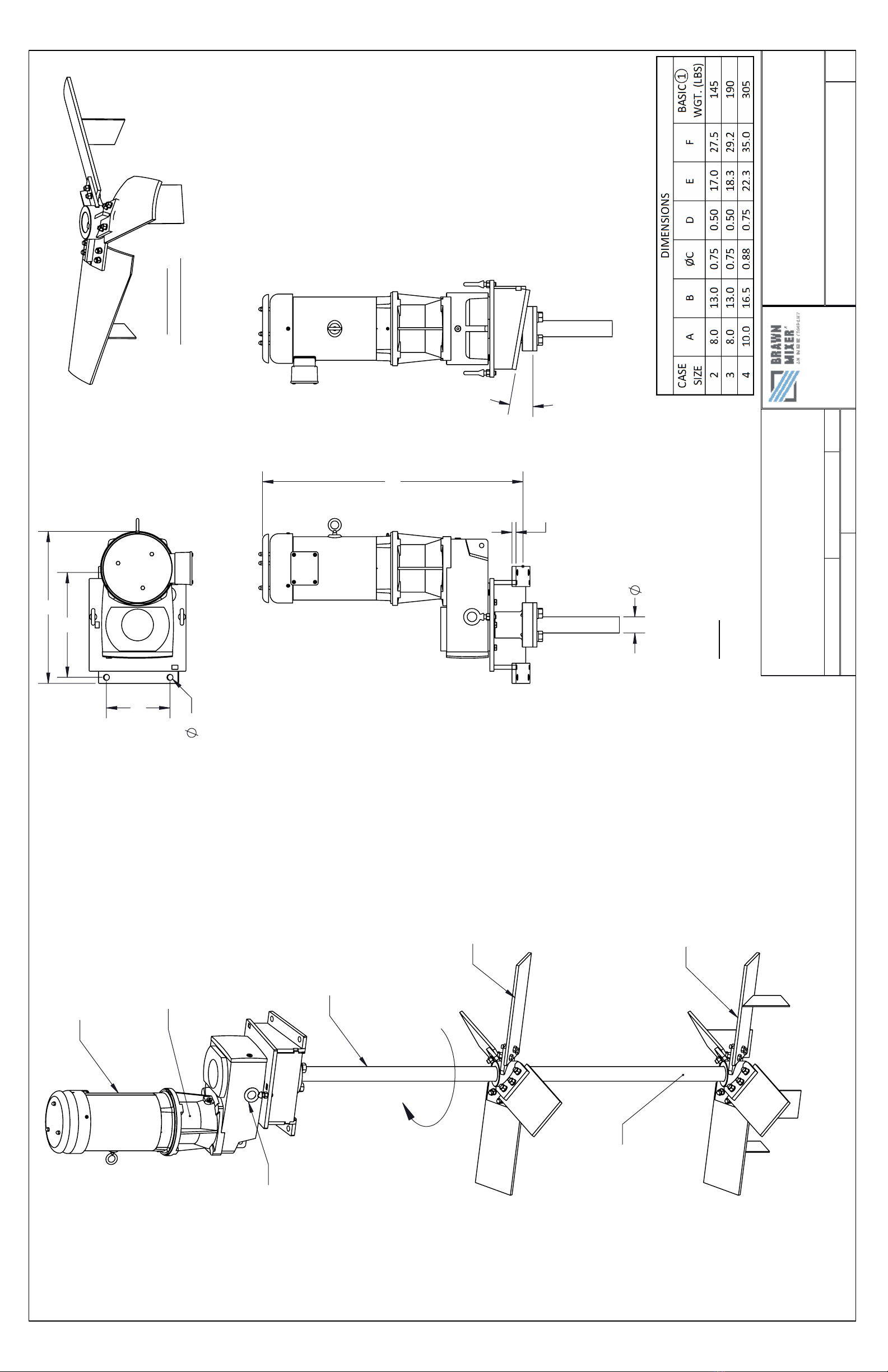
the motor and observe mixer shaft rotation. Proper
rotation is clockwise, as viewed from the top, unless
otherwise noted.
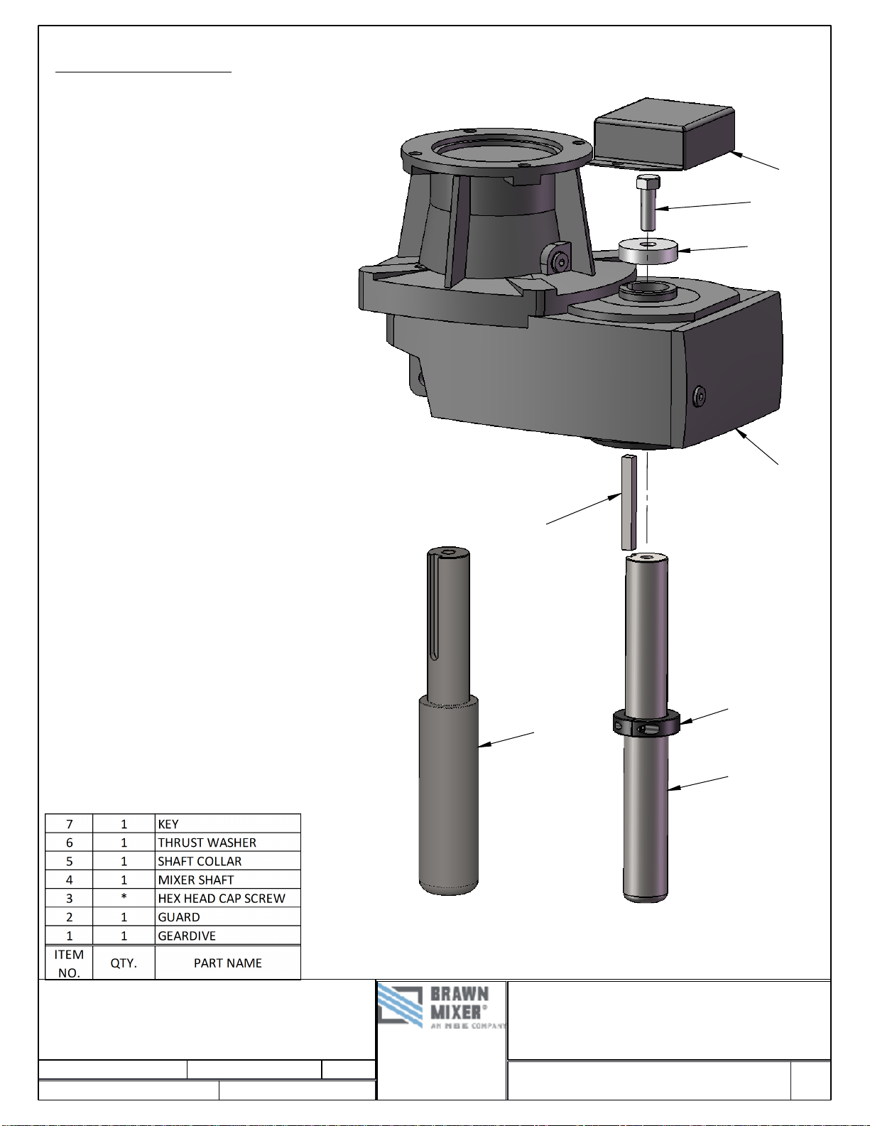
3. Check all bolts and fasteners for tightness. It is good
maintenance practice to recheck all bolts after two
weeks of operation and periodically thereafter. Refer
to TABLE 1 for recommended torque values.
4. Do not attempt to start mixer with impellers buried in
solids or solidified liquids.
CAUTION
Do not operate mixer with the tank empty or the lowest
impeller submerged with less than ½ of the impeller
diameter of liquid above it. Damage to the mixer and/or
mounting structure may result.
ELECTRIC MOTORS
This equipment contains HAZARDOUS VOLTAGES,
ROTATING PARTS AND HOT SURFACES. SEVERE
PERSONAL INJURY OR PROPERTY DAMAGE CAN
RESULT IF SAFETY INSTRUCTIONS ARE NOT
FOLLOWED. Only qualified personnel should work on or
around this equipment after becoming thoroughly familiar
with all warnings, safety notices, and maintenance
procedures contained herein. The successful and safe
operation of this equipment is dependant upon proper
handling, installation, operation and maintenance.
WARNING
Explosion-proof motors—these motors are constructed
to comply with the U.L. Label Service Procedure Manual.
When repairing and reassembling a motor that has an
underwriter’s label, it is imperative that the unit be
reinspected and:
1. All original fits and tolerances be maintained.
2. All plugs and hardware be securely fastened.
3. Any parts replacements, including hardware, be
accurate duplicates of the originals.
Repair work on explosion-proof motors can only be done
by the original manufacturing or U.L. certified shops.
Violations of any of the above items will invalidate the
significance of the U.L. Label.
STORAGE
Motors must be stored in a clean, dry, well-ventilated
location free from vibration and rapid or wide
temperature variations. If the unit is to be stored longer
than three months, consult factory. Ball bearing motors
are shipped from the factory properly lubricated and
ready to operate. When in storage, the motor shaft must
be turned several rotations every month and bearings
relubricated every year. On non-explosion-proof TEFC
motors, a removable plug in the bottom of the frame or
housing permits removal of accumulated moisture. Drain
regularly if storage atmosphere results in formation of
condensation.
INSTALLATION
Installation must be handled by qualified service or
maintenance personnel.
OPERATION
CAUTION
Repeated trial starts can overheat the motor and may
result in motor burnout. If repeated trial starts are made,
allow sufficient time between trials to permit heat to
dissipate from windings and rotor to prevent overheating.
Starting currents are several times running currents, and
heating varies as the square of the current.
After installation is completed, but before motor is put in
regular service, make an initial start as follows:
1. Check motor starting and control device
connections against wiring diagrams.Check
voltage, phase, and frequency of line circuit (power
supply) against motor nameplate.

BTO-SERIES OPERATION & MAINTENANCE MANUAL
12838 Stainless Drive, Holland, MI 49424 Phone: 616/399-5600 Fax 616/399-3084
Copyright 2018 BRAWN Mixer www.BRAWNMIXER.com Page 5 of 9
11/27/2018
ELECTRIC MOTORS, Cont.
2. If possible, remove external load (disconnect drive)
and turn shaft by hand to ensure free rotation. This
may have been done during the installation
procedure; if so, and conditions have not changed,
this check may not be necessary.
a. If drive is disconnected, run motor at no load
long enough to be certain that no unusual
conditions develop. Listen and feel for
excessive noise, vibration, clicking, or
pounding. If present, stop motor immediately.
Investigate the cause and correct before
putting motor in service.
b. If drive is not disconnected, interrupt the
starting cycle after motor has accelerated to
low speed. Carefully observe for unusual
conditions as motor coasts to a stop.
3. When checks are satisfactory, operate at minimum
load and look for unusual conditions. Increase load
slowly to maximum. Check unit for satisfactory
operation.
CAUTION
Guard against overloading. Overloading causes
overheating and overheating means shortened insulation
life. A motor subjected to a 10°C temperature rise above
the maximum limit for the insulation may cause the
insulation life to be reduced by 50%. To avoid
overloading, be sure motor current does not exceed
nameplate current when nameplate voltage is applied.
Electric motors operating under normal conditions
become quite warm. Although some places may feel hot
to the touch, the unit may be operational within limits.
Use a thermocouple to measure winding temperature.
The total temperature, not the temperature rise, is the
measure of safe operation. Investigate the operating
conditions if the total temperature measured by a
thermocouple placed on the windings exceeds:
230°F (110°C) for class “B” insulation
275°F (135°C) for class “F” insulation
302°F (150°C) for class “H” insulation
VOLTAGE REGULATION
Motors will operate successfully under the following
conditions of voltage and frequency variation, but not
necessarily in accordance with the standard established
for operation under rated conditions:
1. When the variation in voltage does not exceed
10% above or below normal, with all phases
balanced.
2. When the variation in frequency does not exceed
5% above or below normal.
3. When the sum of the voltage and frequency of the
voltage does not exceed 10% above or below
normal (provided the frequency variation does not
exceed 5%).
MAINTENANCE
Failure to properly maintain the equipment can result in
severe personal injury and product failure. The
instructions contained herein should be carefully
reviewed, understood and followed. The following
maintenance procedures should be performed regularly:
1. Bearing lubrication
2. Insulation resistance check
3. Cleaning
This checklist does not represent an exhaustive survey
of maintenance steps necessary to ensure safe
operation of the equipment. Particular applications may
require further procedures.
Dangerous voltages are present in the equipment which
can cause severe personal injury and product failure.
Always de-energize and ground the equipment before
maintenance. Maintenance should be performed only by
qualified personnel.
The use of unauthorized parts in the repair of the
equipment, tampering by unqualified personnel, or
removal or alteration of guards or conduit covers will
result in dangerous conditions which can cause severe
personal injury or equipment damage. Follow all safety
instructions contained herein.

BTO-SERIES OPERATION & MAINTENANCE MANUAL
12838 Stainless Drive, Holland, MI 49424 Phone: 616/399-5600 Fax 616/399-3084
Copyright 2018 BRAWN Mixer www.BRAWNMIXER.com Page 6 of 9
11/27/2018
ELECTRIC MOTORS, Cont.
BEARING LUBRICATION
CAUTION
Do not lubricate motor while in operation, since excess
grease will be forced through the bearings and into the
motor before it will force its way out of the drain plug.
Excess grease accumulation on windings reduces
insulation life.
Prior to shipment, motor bearings are lubricated with the
proper amount and grade to provide six months of
satisfactory service under normal operation and
conditions.
For best results, grease should be compounded from a
polyurea base and a good grade of petroleum oil. It
should be of No. 2 consistency and stabilized against
oxidation. Operating temperature ranges should be from
-15°F to +250°F for class B insulation, and to +300°F for
classes F and H. Most leading oil companies have
special bearing greases that are satisfactory.
Relubricate bearings every six months (more often if
conditions require) as follows:
1. Stop the motor. Lock out the switch.
2. Thoroughly clean off pipe plugs and remove
from housings.
3. Remove hardened grease from drains with a stiff
wire or rod.
4. Add grease to inlet with hand gun until small
amount of new grease is forced out drain.
5. Remove excess grease from ports, replace inlet
plugs, and run motor ½ hour before replacing
drain plug.
6. Put motor back in operation.
INSULATION RESISTANCE
Check insulation resistance periodically. Any approved
method of measuring insulation resistance may be used,
provided the voltage across the insulation is at a safe
value for the type and condition of the insulation. A hand
crank megger of not over 500 volts is the most
convenient and safe method. Standards of the Institute
of Electrical and Electronics Engineers, Inc., recommend
that the insulation resistance of the stator windings at 75°
C, measured at 500 volts dc, after one minute should not
be less than:
Rated Voltage of Machine + 1000
=
Insulation Resistance
1000
in Megohms
This formula is satisfactory for most checks. For more
information, see IEEE Standard No. 43 “Recommended
Practice for Insulation Resistance Testing of AC Rotating
Machinery.”
CLEANING
WARNING
Do not attempt to clean the motor while it is operating.
Contact with rotating parts can cause severe personal
injury or property damage. Stop the motor and lock out
switch before cleaning.
The motor exterior must be kept free of oil, dust, water,
and chemicals. For fan-cooled motors, it is particularly
important to keep the air intake openings free of foreign
material. Do not block air outlet or inlet.
On non-explosion-proof TEFC motors, a removable plug
in the bottom center of the motor frame or housing
permits removal of accumulated moisture. Drain
regularly.
MAINTENANCE / LUBRICATION
Gear units should have the oil changed every 10,000
hours or 2 years. If synthetic lubricant is used, it should
be changed every 20,000 hours or 4 years. For adverse
operating conditions, the interval should be shorter. DO
NOT MIX SYNTHETIC AND MINERAL BASED OILS.
Units should be checked periodically for increased noise,
surface temperature, vibration, shaft movement and
amperage draw. Units with inspection covers should not
be operated with the inspection cover removed.
CAUTION
Oil should be changed more often if reducer is used in a
severe environment (i.e., dusty, humid).

BTO-SERIES OPERATION & MAINTENANCE MANUAL
12838 Stainless Drive, Holland, MI 49424 Phone: 616/399-5600 Fax 616/399-3084
Copyright 2018 BRAWN Mixer www.BRAWNMIXER.com Page 7 of 9
11/27/2018
MAINTENANCE / LUBRICATION,
Cont.
All reducers are shipped from the factory properly filled
with lubricant, and all plugs are installed according to the
mounting position given on the reducer nametag.
Acceptable oil level is within ½ inch of the bottom of the
fill plug threads. Consult the sticker adjacent to the fill
plug to determine the type of lubricant installed at the
factory. Standard lubricant is ISO VG220 mineral-based
oil. However, some units have special lubricants
designed to operate in certain environments or to extend
the service life of the lubricant. If in doubt about which
lubricant is needed, contact Brawn.
TABLES 2 and 3offer suggestions on the viscosity and
manufacturers of recommended lubricants.
CAUTION
In the Food and Drug Industry (including animal food),
consult the lubrication supplier for recommendation of
lubricants which are acceptable to the Food and Drug
Administration and/or other authoritative bodies having
jurisdiction. Factory supplied oil is not suitable for these
applications or this industry.
CASE SIZE OIL CAPACITY
22.1
34.3
45.7
59.3
TABLE 2: APPROXIMATE OIL
CAPACITY (QTS.) FOR GEAR DRIVES
AUTOVENT PLUG: The Autovent plug (FIGURE 3) is
brass in color and will be located at the highest point on
the gearbox. It operates like a check-valve to allow the
reducer to relieve internal pressure while preventing
lubricant contamination during cooling. A spring presses
a ball or plunger against a machined orifice until
pressure exceeds 2 psi. Above 2 psi, the air is allowed to
escape depressurizing the gearcase. When internal
pressure drops below 2 psi, the autovent reseals closing
the unit to the outside environment. After shutdown, the
reducer cools along with the air inside the reducer. The
unit will temporarily maintain a slight vacuum until
normalization occurs.
FIGURE 3: THE AUTOVENT RELEASES BUILT-UP
AIR PRESSURE FROM INSIDE THE GEARBOX (MAX.
PRESSURE 2PSI).
FILL LEVEL & DRAIN PLUGS:The drain plugs
(FIGURE 4) are metric socket head cap screws. They
will be located at the lowest part of the gearbox for ease
of draining. The fill level plug is a hex head cap screw. It
will be located between the Autovent and the drain plug.
Both types of plugs will have gaskets included to prevent
oil from leaking.
FIGURE 4: TWO TYPES OF PLUGS FOR
MAINTENANCE.

BTO-SERIES OPERATION & MAINTENANCE MANUAL
12838 Stainless Drive, Holland, MI 49424 Phone: 616/399-5600 Fax 616/399-3084
Copyright 2018 BRAWN Mixer www.BRAWNMIXER.com Page 8 of 9
11/27/2018
TABLE 3: RECOMMENDED LUBRICANTS
STORAGE
Units shipped from Brawn Mixer are intended to be used within 30 days after receipt and presumed to be stored indoors in
a heated building. Store mixers as packaged by the factory. If you intend on storing units under adverse conditions or for a
long period of time, special storage precautions will be necessary.
1. Store in a sheltered area away from chemical vapors or steam.
2. Cover.
3. Do not store in sunlight or near high heat.
4. Spray oil on exposed shafts and seals. Remove oil on start-up.
5. Rotate output shaft 360º every 3-4 weeks.
6. Mixers should not be stored near vibrating machinery to avoid damage to the bearings.
7. If electric motors have been subjected to humid conditions, check the insulation resistance between phase and mass and
between the different phases. The resistance should not be less than 100 megohms. If the resistance is less, please consult
the factory.
Ambient
Temperature (F)
Formulation
Oil
Manufacturer
Oil Brand Name
20° to
Mineral
Texaco
Meropa
20° to
Mineral
Shel
Omala EP
Ambient
Temperature (F)
Formulation
Oil
Manufacturer
Oil Brand Name
14° to
Syntheti
Texaco
Pinnacle EP680
14° to
Syntheti
Shel
Omala HD 680
-13° to
Syntheti
Texaco
Pinnacle EP220
-13° to
Syntheti
Shel
Omala HD 220
-40° to 50°
Syntheti
Texaco
Pinnacle EP32
-40° to 50°
Syntheti
Shel
Omala HD
20° to
Food
Chevro
FM ISO 220
20° to
Synthetic Food Grade
OilJA
Magnaplate 85W140-FG
5° to
Fluid Grease
Mobi
Mobilux
-30° to
Synthetic Fluid Grease
Mobi
Mobilith SHC
-30° to
Synthetic Fluid Grease
Shel
Tivela Compound A
Ambient
Temperature (F)
Formulation
Grease
Manufacturer
Grease Brand Name
-20° to
Mineral
Texaco
Multifak
-20° to
Mineral
Shel
Cypernia RA/C3
Ambient
Temperature (F)
Formulation
Grease
Manufacturer
Grease Brand Name
-58° to
Syntheti
Texaco
Starfak 2202
-58° to
Syntheti
Shel
Aero
5° to
Food
Lubriplate
SIF 1
STANDARD OIL - ISO
OPTIONAL
STANDARD BEARING GREASE - NL GI 2EP Lithium
OPTIONAL BEARING

BTO-SERIES OPERATION & MAINTENANCE MANUAL
12838 Stainless Drive, Holland, MI 49424 Phone: 616/399-5600 Fax 616/399-3084
Copyright 2018 BRAWN Mixer www.BRAWNMIXER.com Page 9 of 9
11/27/2018
WARRANTY
WARRANTY: All equipment or parts covered by this
manual are guaranteed free from defective material and
workmanship for a period of twelve (12) months from
date of shipment, under normal use and service. This
warranty does not cover failure of normal wear parts
unless the failure of such part has resulted from
defective material and workmanship. BRAWN Mixer will
repair or replace, at its option, any equipment which has
been found to be defective and is within the warranty
period, provided that the equipment is shipped, with
previous factory authorization, freight prepaid, to
BRAWN's plant in Holland, Michigan, USA. All return
shipments are made FOB BRAWN's factory. BRAWN is
not responsible for removal, installation, or any other
incidental expenses incurred in shipping the equipment
to or from BRAWN. In the case of components
purchased by BRAWN Mixer and incorporated in the
equipment, the component manufacturer's guarantee
shall apply. NOTE: Any modifications or corrective work
done to the equipment which were not specifically
authorized in writing by BRAWN Mixer shall void this
limited warranty, and BRAWN Mixer shall accept no
liability for any of the corrective work or expenditures
which were conducted without their prior, written
authorization. BRAWN Mixer shall not be held liable for
any further cost, expense, or labor to replace equipment
or replaceable parts, or indirect or consequential
damages.
With the exceptions of the limited warranty set out
above, there are no other understandings, agreements,
representations, or warranties implied (including any
regarding the merchantability or fitness for a particular
purpose), not specified herein, respecting this agreement
or equipment, hereunder. This contract states the entire
obligation of BRAWN Mixer in connection with this
transaction.
SHOULD WE MAKE A MISTAKE...
BRAWN Mixer's
Direct Returns Policy
To ensure proper handling of your return, please take a
moment to read the following:
ALL returns require a RETURN GOODS
AUTHORIZATION (RGA) NUMBER. We are unable
to process your return or issue proper credit without
an approved RGA number.
ALL returns must be COMPLETE, including all
original warranties, manuals, documentation and
packaging.
ALL product must be received within 14 days of
issuing an RGA number.
How to Return Product
You must have a RGA number before you return any
product to BRAWN Mixer. To obtain this number, call
616/399-5600 and ask for Customer Service. Be sure to
have available the following information:
your order number
the BRAWN product serial number
the part number and description of the product
the reason for the return
♦I M P O R T A N T ♦
The RGA number must be written clearly on all boxes
being returned. C.O.D. shipments will not be accepted.

BIM 1020/2005/03 1 www.nord.com
BIM 1020
UNICASE®Shaft Mount Gearboxes
Installation and Maintenance Instructions
Retain These Safety Instructions For Future Use
INSPECTION OF UNIT
Thoroughly inspect the equipment for any shipping and handling damage before accepting shipment from the freight company. If any of the
goods called for in the bill of lading or express receipt are damaged or the quantity is short, do not accept until the freight or express agent
makes an appropriate notation on your freight bill or express receipt. If any concealed loss or damage is discovered later, notify your freight
carrier or express agent at once and request him to make an inspection. We will be very happy to assist you in collecting claims for loss or
damage during shipment; however, this willingness on our part does not remove the transportation company’s responsibility in reimbursing
you for collection of claims or replacement of material. Claims for loss or damage in shipment must not be deducted from the NORD Gear
invoice, nor should payment of the NORD Gear invoice be withheld awaiting adjustment of such claims, as the carrier guarantees safe
delivery.
If considerable damage has been incurred and the situation is urgent, contact the nearest NORD Gear Sales Office for assistance. Please
keep a written record of all communications.
RECORD NAMEPLATE DATA
Locate the gear reducer nameplate and record all nameplate data for future reference.
SK ________________________________________________________ S/N _________________________________
RATIO ______________ MAX TORQUE ____________________ RPM ______________ MTG. POS ______________
STORAGE
PROPER STORAGE UNTIL INSTALLED
Keep unit in a dry, temperature controlled area. If stored other
than said, long term storage methods must be applied to the unit
including complete fill with lubricant. Protect machined surfaces
and rotate shafts periodically. Prior to putting unit into service,
drain lubricant and refill to proper level as determined by the
mounting position.
PROPER HANDLING OF THE UNIT
Exercise care to prevent damage to the unit when moving. Lift
onIy at designed Iifting points. Do not attach other machinery and
lift by the unit lifting points. The lifting points are to be used to lift
the unit only. Insure that adequate safety measures are taken to
protect personneI during transportation. Protect the mounting
surface from damage.
CDN
USA

BIM 1020/2005/03 2 www.nord.com
INSTALLATION OF UNIT
To ensure Iong service and dependabIe performance, an encIosed gear drive must be rigidIy supported and the shafts accurateIy aIigned.
The foIIowing describes the minimum precautions required to accompIish this end.
FOUNDATION
The responsibiIity for the design and construction of the
foundation Iies with the user. The foundation must be adequate
to withstand normaI operating Ioads and possibIe overIoads whiIe
maintaining aIignment to attached system components under
such Ioads.
MOUNTING POSITION
UnIess a unit is specificaIIy ordered for incIined mounting, the
foundation must be IeveI and fIat. The Iubrication system may
not operate properIy if the unit is not mounted in the position for
which it is designed. It may be desirabIe to eIevate the
foundation to faciIitate oiI drainage.
CONCRETE FOUNDATION
If a concrete foundation is used, steeI mounting pads and boIts of
sufficient size to distribute the stress into the concrete shouId be
grouted into the foundation.
STEEL FOUNDATION
If a structuraI steeI foundation is used (i.e. wide fIange beams or
channeIs), a base pIate or soIe pIate of suitabIe thickness shouId
be used and shouId extend under the entire unit.
FOOT MOUNTED UNITS
Use shims under the feet of the unit to aIign the output shaft to
the driven equipment. Make sure that aII feet are supported so
that the housing wiII not distort when it is boIted down. Improper
shimming wiII reduce the Iife of the unit and may cause faiIure.
DoweI pins may be instaIIed to prevent misaIignment and ensure
proper reaIignment if removed for service.
SHAFT MOUNTED UNITS
Shaft mounted drives should be mounted as close to the driven
equipment bearing support as possible to minimize bearing loads
due to overhung load. Design of the joint connection between the
torque reaction arm and the foundation is the user’s responsibility.
HoIIow Shaft Diameter toIerance
Metric (mm)
d18 = +0.018/-0.000
!18 d30 = +0.021/-0.000
!30 d50 = +0.025/-0.000
!50 d80 = +0.030/-0.000
!80 d120 = +0.035/-0.000
!120 d180 = +0.040/-0.000
Inch
d4.375 = +0.0010 / -0.0000
!4.375 = +0.0015 / -0.0000
Customer shaft diameter toIerances with keyed hoIIow shafts
Metric (mm)
d18 = +0.000/-0.011
!18 d30 = +0.000/-0.013
!30 d50 = +0.000/-0.016
!50 d80 = +0.000/-0.019
!80 d120 = +0.000/-0.022
!120 d180 = +0.000/-0.025
Inch
d1.500 = +0.000/-0.002
!1.500 d2.500 = +0.000/-0.003
!2.500 d7.000 = +0.000/-0.004
Shaft finish to be 125 micro inches or smoother.
Customer shaft diameter toIerance with Shrink Disc fit h6
Metric (mm)
d18 = +0.000/-0.011
!18 d30 = +0.000/-0.013
!30 d50 = +0.000/-0.016
!50 d80 = +0.000/-0.019
!80 d120 = +0.000/-0.022
!120 d180 = +0.000/-0.025
Inch
d0.750 = +0.0000/-0.0004
!0.750 d1.125 = +0.0000/-0.0005
!1.125 d2.000 = +0.0000/-0.0006
!2.000 d3.000 = +0.0000/-0.0007
!3.000 d4.750 = +0.0000/-0.0008
!4.750 d7.000 = +0.0000/-0.0010
Shaft finish to be 125 micro inches or smoother.
Customer shaft diameter toIerance with Shrink Disc fit f6
(Iooser fit)
Metric (mm)
d18 = -0.016/-0.024
!18 d30 = -0.020/-0.029
!30 d50 = -0.025/-0.036
!50 d80 = -0.030/-0.043
!80 d120 = -0.036/-0.051
!120 d180 = -0.043/-0.061
Inch
d0.750 = -0.0006/-0.0011
!0.750 d1.125 = -0.0008/-0.0013
!1.125 d2.000 = -0.0010/-0.0016
!2.000 d3.000 = -0.0012/-0.0019
!3.000 d4.750 = -0.0014/-0.0023
!4.750 d7.000 = -0.0017/-0.0027
Shaft finish to be 125 micro inches or smoother
FLANGE MOUNTED UNITS
If a structuraI steeI foundation is used (i.e. wide fIange beams or
channeIs), a base pIate or soIe pIate of suitabIe thickness shouId
be used and shouId extend under the entire unit. If a buIk head
pIate is used it shouId be of proper strength to minimize buckIing
distortions.
FIange PiIot ‘AK’ or ‘AK1’ toIerance
Metric (mm)
!50 d80 = +0.012/-0.007
!80 d120 = +0.013/-0.009
!120 d180 = +0.014/-0.011
!180 d230 = +0.016/-0.013
!230 d315 = +0.000-0.032
!315 d400 = +0.000/-0.036
!400 d500 = +0.000/-0.040
Inch
!1.969 d3.150 = +0.005/-0.0003
!3.150 d4.724 = +0.005/-0.0004
!4.724 d7.087 = +0.006/-0.0004
!7.087 d9.055 = +0.006/-0.0005
!9.055 d12.402 = +0.000/-0.0013
!12.402 d15.748 = +0.000/-0.0014
!15.748 d19.685 = +0.000/-0.0016
BOLT STRENGTH
BoIt size, strength and quantity shouId be verified to insure proper
torque reaction capacity whatever the mounting arrangement.
LUBRICATE SHAFTS
Both the hollow shaft and the driven shaft should be liberally
lubricated before assembly. The unit must slide freely onto the
driven shaft. Do not hammer or force the unit into place. For
shrink disc, follow instructions below.

BIM 1020/2005/03 3 www.nord.com
AXIAL RETENTION
Each drive shaft must be retained in place relative to the gear
reducer. Or each gear reducer must be retained in place relative
to the drive shaft. Either way NORD recommends the use of
shaft shoulders, locking collars or FIXING ELEMENTS to axially
retain the shaft or gear reducer in position.
SET SCREWS
If set screws are used for axial retention, they should be tightened
evenly. Flats may be filed on the driven shaft and a thread-
locking adhesive used for more position retention.
SNAP RING RETENTION
Placing external snap rings on drive shafts must be performed
with caution. The groove, which the snap ring fits into, may
weaken the drive shaft causing premature failure. NORD does
not recommend this type of shaft retention.
THRUST PLATE
In applications, which are subject to high vibratory loads, a thrust
plate will provide greater resistance to axial movement. Follow
the manufacturer’s recommendations for assembly.
SHRINK DISC
If a shrink disc is used to secure a reducer hollow shaft to the
driven shaft, follow this assembly procedure. Start with the shrink
disc mounted onto the extension of the hollow shaft disc locking
bolts loosened.
1. Clean reducer bore and mating solid shaft to be free of any
lubricants or dirt.
2. Slide reducer onto the solid shaft until it is about half way
through.
3. Lubricate the remaining portion of the solid shaft with a #2
grease or similar lubricant. This part will be located under
the bronze bushing. Do not install grease under the
shrink disc gripping area. Finish installing the solid shaft
into the reducer hollow bore.
4. Finger tighten all shrink disc bolts. Now, moving a circular
pattern, tighten each shrink disc locking bolt 1/4 to 1/2 turn.
Do not use criss cross pattern. Continue tightening in the
same circular direction with 1/4 or 1/2 turn increments until
all bolts reach the specified bolt tightening torque. Bolt
tightening torque is shown on the shrink disc label for the
particular unit.
5. Run unit for 24 hours, then retighten shrink disc locking bolts
to the proper bolt torque as indicated above.
TORQUE REACTION ARM
On the shaft mount ‘Clincher’, torque is reacted through the
integral torque tab, which is part of the casting. Commonly,
NORD’s optional RUBBER BUFFER bushings are installed on
each side of the integral torque tab to dampen torque shocks and
allow for mis-alignment received from the machinery during
operation.
Torque arm connection fabrications should always be mounted
perpendicular to a line through the output shaft center and the
point at attachment of the torque arm to the unit housing. In this
position the minimum load on the attachment structure arm will be
experienced. The attachment structure must be rigid and may not
deflect under any load. Doing so will place extra loads on the
output bearings of the reducer.
PRIME MOVER MOUNTING
AIign the prime mover to the reducer-input shaft using shims
under the feet. Make sure that the feet are supported. DoweI the
prime mover to its foundation.
SHAFT CONNECTIONS
When connecting shafts to either the input or output of the
reducer, consider the foIIowing instructions.
FITS
CIearance or interference fits for coupIing hubs shouId be in
accordance with ANSI/AGMA 9002-A86 or as follows.
Output and Input shaft Diameter toIerance
Metric (mm)
d18 = +0.012/+0.001
!18 d30 = +0.015/+0.002
!30 d50 = +0.018/+0.002
!50 d80 = +0.030/+0.011
!80 d120 = +0.035/+0.013
!120 d180 = +0.040/+0.015
Inch
d1.750 = +0.0000/-0.0005
!1.750 = +0.0000/-0.0010
Output and Input shaft DriII and tap shaft end
Metric (mm)
d16 = M5
!16 d21 = M6
!21 d24 = M8
!24 d30 = M10
!30 d38 = M12
!38 d50 = M16
!50 d85 = M20
!85 d130 = M24
Inch
d0.438 = #10-24 x 0.4 deep
!0.438 d0.813 = 1/4-20 x 0.6 deep
!0.813 d0.938 = 5/16-18 x 0.7 deep
!0.938 d1.125 = 3/8-16 x 0.9 deep
!1.125 d1.375 = 1/2-13 x 1.1 deep
!1.375 d1.875 = 5/8-11 x 1.4 deep
!1.875 d3.250 = 3/4-10 x 1.7 deep
!3.250 = 1-8 x 2.2 deep
Outboard pinion and sprocket fits shouId be as recommended by
the pin sprockets with interference fits shouId be heated
according to the manufacturer’s recommendations, generaIIy
250qF to 300qF, (120qC to 150qC) before assembIing to the shaft.
LOCATION
CoupIing hubs shouId be mounted fIush with the shaft ends,
unIess specificaIIy ordered for overhung mounting. Pinions,
sprockets and sheaves shouId be mounted as cIose as possibIe
to the unit housing to minimize bearing Ioads and shaft
defIections.

BIM 1020/2005/03 4 www.nord.com
WARNING:
LOCK OUT POWER before any maintenance is performed.
Make absolutely sure that no voltage is applied while work is
being done on the gearbox.
The Autovent releases built-up air pressure from
inside the gearbox (Max. pressure 2 psi).
COUPLING ALIGNMENT
Shaft coupIings shouId be instaIIed according to the coupIing
manufacturer’s recommendations for gap, anguIar and paraIIeI
aIignment. In many instaIIations, it is necessary to aIIow for
thermaI and mechanicaI shaft movement when determining shaft
aIignment. The coupIing manufacturer’s recommendations
shouId be foIIowed.
AXIAL DISPLACEMENT
The gap between shaft ends shouId be the same as the specified
coupIing gap unIess overhung mounting of the coupIing hub is
specified. The coupIing gap and shaft gap must be sufficient to
accommodate any anticipated thermaI or mechanicaI axiaI
movement.
ANGULAR ALIGNMENT
Insert a spacer or shim stock equaI to the required coupIing gap
between the coupIing hub faces and measure the cIearance using
feeIer gauges. Repeat this at the same depth at 90-degree
intervaIs to determine the amount of anguIar misaIignment.
PARALLEL ALIGNMENT
Mount a diaI indicator to one coupIing hub, and rotate this hub,
sweeping the outside diameter of the other hub. The paraIIeI
misaIignment is equaI to one-haIf of the totaI indicator reading.
Another method is to rest a straight edge squareIy on the outside
diameter of the hubs at 90-degree intervaIs and measure any
gaps with feeIer gauges. The maximum gap measurement is the
paraIIeI misaIignment.
CHECKING ALIGNMENT
After both anguIar and paraIIeI aIignments are within specified
Iimits, tighten aII foundation boIts secureIy and repeat the above
procedure to check aIignment. If any of the specified Iimits for
aIignment are exceeded, reaIign the coupIing.
SPROCKET OR SHEAVE ALIGNMENT
AIign the sheaves or sprockets square and paraIIeI by pIacing a
straight edge across their faces. AIignment of bushed sheaves
and sprockets shouId be checked after bushings have been
tightened. Check horizontaI shaft aIignment by pIacing a IeveI
verticaIIy against the face of the sheave or sprocket. Adjust beIt
or chain tension per the manufacturer’s specified procedure.
OUTBOARD PINION ALIGNMENT
AIign the pinion by adjusting the gear tooth cIearance according
to the manufacturer’s recommendations and checking for
acceptabIe outboard pinion tooth contact. The foundation boIts
may have to be Ioosened and the unit moved sIightIy to obtain
this contact. When the unit is moved to correct tooth contact, the
prime mover shouId be reaIigned.
RECHECK ALIGNMENT
After a period of operation, recheck aIignment and adjust as
required.
1. Properly install unit on a rigid foundation
x adequateIy supported
x secureIy boIted into pIace
x IeveIed so as not to distort the gear case
2. Properly install couplings suitabIe for the application and
connected equipment.
3. Ensure accurate aIignment with other equipment.
4. Furnish and install adequate machinery guards as needed to
protect operating personneI and as required by the
appIicabIe standards of the OccupationaI Safety and HeaIth
Administration (OSHA), and by other appIicabIe safety
reguIations;
5. Ensure that driving equipment is running in the correct
direction before coupling to reducers with backstops
(designed to operate onIy in a specific direction) or
machinery designed to operate only in one direction.
CHANGES IN PERFORMANCE SPECIFICATIONS
Owner has the responsibiIity to consult with NORD GEAR if such
items such as applied Ioads, operating speeds or other operating
conditions have changed.
START-UP
1. Ensure that switches, aIarms, heaters, coolers and other
safety and protection devices are instaIIed and operational
for their intended purpose.
2. Verify that the installed mounting position is the same as the
nametag mounting position. If not, adjust the oil level
accordingly and relocate the vent plug, fill plug and drain
plug according to the mounting position. See following.
AUTOVENT PLUG
The Autovent plug is brass in color and will be located at the
highest point on the gearbox. It operates like a check-valve to
allow the reducer to relieve internal pressure while preventing
lubricant contamination during cooling. A spring presses a ball or
plunger against a machined orifice until pressure exceeds 2 psi.
Above 2 psi the air is allowed to escape depressurizing the
gearcase. When internal pressure drops below 2 psi, the
autovent re-seals closing the unit to the outside environment.
After shutdown, the reducer cools along with the air inside the
reducer. The unit will temporarily maintain a slight vacuum until
normalization occurs. NORD Gear supplies an Autovent as a
standard feature.

BIM 1020/2005/03 5 www.nord.com
Two types of plugs for maintenance
FILL LEVEL & DRAIN PLUGS
The drain plugs are metric socket head cap screws. They will be
located at the lowest part of the gearbox for ease of draining. The
fill level plug is a hex head cap screw. It will be located between
the Autovent and drain plug. Both types of plugs will have gaskets
included to prevent oil from leaking.
LUBRICANT
AII NORD reducers are shipped from the factory properIy fiIIed
with Iubricant and all plugs are installed according to the mounting
position given on the reducer nametag. Acceptable oil fill level is
within ½ inch of the bottom of the fill plug threads.
OPERATION AND MAINTENANCE CHECKLIST
1. Operate the equipment as it was intended to be operated
2. Do not overIoad.
3. Run at correct speed.
4. Maintain Iubricant in good condition and at proper IeveI.
5. Dispose of used Iubricant in accordance with appIicabIe
Iaws and reguIations.
6. AppIy proper maintenance to attached equipment at
prescribed intervaIs recommended by the manufacturer.
7. Perform periodic maintenance of the gear drive as
recommended by NORD.
MOUNTING POSITIONS
These charts detail the mounting positions for horizontal and vertical mounting. The Autovent, oil fill plug and drain plug are indicated on each
mounting position picture. The factory set mounting position and plug locations match that shown on the gearbox nametag. For mounting
orientations other than shown consult NORD Gear.
H1 H2 H3 H4
SK 6282 - SK 11282
SK 6382 - SK 12382
SK 1282 - SK 5282
SK 6282 - SK 11282
SK 6382 - SK 12382
SK 2382 - SK 5382
SK 1282 - SK 5282
SK 6382 - SK 12382
SK 2382 - SK 5382
H5* H6
Symbols: Vent plug Oil level Drain plug
*Mounting position H5 with lubricant
expansion unit recommended
Horizontal position
Vertical position
SK 1282 - SK 5282
SK0182NB & SK1382NB have no vent or drain plugs. They are filled with synthetic oil so the units are
“Lubed for Life”.
Table of contents
Other NBE Mixer manuals