NBE BRAWN MIXER BWG Series User manual

OPERATION
AND
MAINTENANCE
MANUAL
SERIAL NUMBER
___________________
CUSTOMER:____________________________
SALES REP.:____________________________
BWG SERIES


PER ORDER
(SEE BELOW)
ADJUSTABLE
J
SHAFT LENGTH
PER ORDER
A
PER ORDER
OPTIONAL
UPPER
IMPELLER
NEMA C-FACE MOTOR
ROTATION
G
D
E
F
B
C
PLAN VIEW
NOTES:
BASIC WEIGHT DOES NOT INCLUDE
1.
SHAFT, IMPELLER(S) OR MOTOR.
ALL DIMENSIONS ARE IN INCHES AND
2.
ARE FOR REFERENCE ONLY UNLESS
CERTIFIED.
FLANGE MOUNTED UNITS ALSO
3.
AVAILABLE. CONSULT FACTORY FOR
APPLICABLE DIMENSIONS.
AF3 HYDROFOIL TURBINE IMPELLERS
4.
SHOWN. OTHER IMPELLERS
AVAILABLE UPON REQUEST OR PER
APPLICATION.
OPTIONAL
"PICKET FENCE"
IMPELLER
*FOR REFERENCE ONLY*
BSB
* ALL DIMENSIONS AND WEIGHTS ARE FOR REFERENCE ONLY
UNLESS THE DRAWING IS CERTIFIED.
* ALL EQUIPMENT DESIGN AND APPLICATION DATA SHOWN
HEREIN IS CONFIDENTIAL AND THE PROPERTY OF BRAWN MIXER.
NO USE OR DISCLOSURE THEREOF MAY BE MADE WITHOUT OUR
WRITTEN PERMISSION.
REV.
DWG.
NO.
A-
MIXER MODEL
DRAWN BY:
DATE:
12838 Stainless Drive
Holland, MI 49424
PH: 616-399-5600
FAX: 616-399-3084
TK0038M
BWG PLATE
10/9/2018
APPROVED BY:
DIMENSION AND ASSEMBLY DRAWING
©
DATE:
2018
OPEN TANK MOUNTED MIXER

PER ORDER
PER ORDER
(SEE BELOW)
ADJUSTABLE
D
A
SHAFT LENGTH
PER ORDER
ROTATION
OPTIONAL UPPER
IMPELLER
PLAN VIEW
*FOR REFERENCE ONLY*
NOTES:
BASIC WEIGHT DOES NOT INCLUDE
1.
SHAFT, IMPELLERS OR MOTOR.
ALL DIMENSIONS ARE IN INCHES AND
2.
ARE FOR REFERENCE ONLY UNLESS
CERTIFIED.
OVERALL HEIGHT DIMENSION (A) MAY
3.
VARY DEPENDING ON SEAL OPTION
SELECTED.
AF3 3 BLADE HYDROFOIL IMPELLERS
4.
SHOWN. OTHER IMPELLERS AVAILABLE
UPON REQUEST OR PER APPLICATION.
LOW PRESSURE STUFFING BOX SHOWN.
5.
SINGLE AND DOUBLE MECHANICAL
SEAL ARE ALSO AVAILABLE.
C
NEMA C-FACE
MOTOR
BSB
* ALL DIMENSIONS AND WEIGHTS ARE FOR REFERENCE ONLY
UNLESS THE DRAWING IS CERTIFIED.
* ALL EQUIPMENT DESIGN AND APPLICATION DATA SHOWN
HEREIN IS CONFIDENTIAL AND THE PROPERTY OF BRAWN MIXER.
NO USE OR DISCLOSURE THEREOF MAY BE MADE WITHOUT OUR
WRITTEN PERMISSION.
REV.
DWG.
NO.
A-
MIXER MODEL
DRAWN BY:
DATE:
12838 Stainless Drive
Holland, MI 49424
PH: 616-399-5600
FAX: 616-399-3084
TK0039M
BWG PEDESTAL
10/9/2018
APPROVED BY:
DIMENSION AND ASSEMBLY DRAWING
©
DATE:
2018
SEALED TANK FLANGE MOUNT MIXER

*FOR REFERENCE ONLY*
2
3
6
1
7
4
5
4
MIXER SHAFT ASSEMBLY
1. ATTACH THE SHAFT COLLAR (ITEM 5)
TO THE MIXER SHAFT (ITEM 4).
2. PLACE THE KEY (ITEM 7) ON THE
MIXER SHAFT AND SLIDE THE MIXER
SHAFT INTO THE HOLLOW OUTPUT
SHAFT ON THE GEARDRIVE (ITEM 1).
3. PLACE THE THRUST WASHER (ITEM 6)
OVER THE HOLLOW OUTPUT SHAFT ON
THE TOP OF THE GEARDRIVE. APPLY
THREADLOCKER TO THE THREADS OF
THE HEX HEAD CAP SCREW (ITEM 3),
INSTALL IT THRU THE THRUST WASHER
AND INTO THE MIXER SHAFT. TORQUE
THE GRADE 5 HEX HEAD CAP SCREW
TO THE RECOMMENDED VALUE IN THE
O&M MANUAL.
4. ATTACH THE GUARD (ITEM 2) ON THE
TOP OF THE GEARDRIVE.
ALTERNATE CONST.
OF SHAFT
* QUANTITY VARIES DEPENDING
ON SHAFT DESIGN.
BSB
* ALL DIMENSIONS AND WEIGHTS ARE FOR REFERENCE ONLY
UNLESS THE DRAWING IS CERTIFIED.
* ALL EQUIPMENT DESIGN AND APPLICATION DATA SHOWN
HEREIN IS CONFIDENTIAL AND THE PROPERTY OF BRAWN MIXER.
NO USE OR DISCLOSURE THEREOF MAY BE MADE WITHOUT OUR
WRITTEN PERMISSION.
REV.
DWG.
NO.
A-
MIXER MODEL
DRAWN BY:
DATE:
12838 Stainless Drive
Holland, MI 49424
PH: 616-399-5600
FAX: 616-399-3084
TK0090
BWG SHAFT ASSEMBLY
10/29/2018
APPROVED BY:
DIMENSION AND ASSEMBLY DRAWING
©
DATE:
2018

BWG-SERIES OPERATION & MAINTENANCE MANUAL
12838 Stainless Drive, Holland, MI 49424 Phone: 616/399-5600 Fax 616/399-3084
Copyright 2018 BRAWN Mixer www.BRAWNMIXER.com Page 1 of 11
11/27/2018
CONTENTS
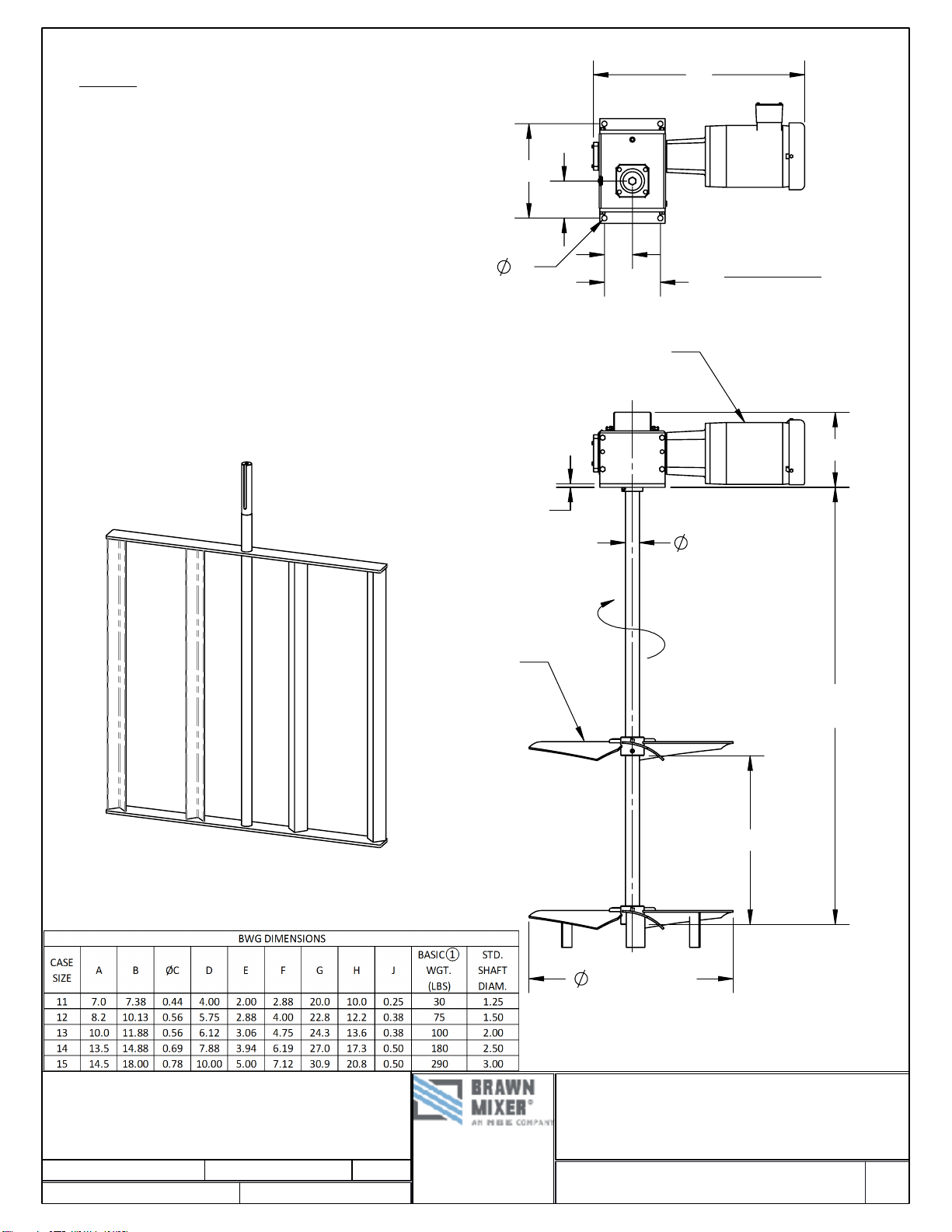
Mixer Installation / Assembly / Dimension Drawings
Safety ............................................................................ 1
Customer Service Contact ............................................ 1
Initial Inspection............................................................. 2
Installation ..................................................................... 2
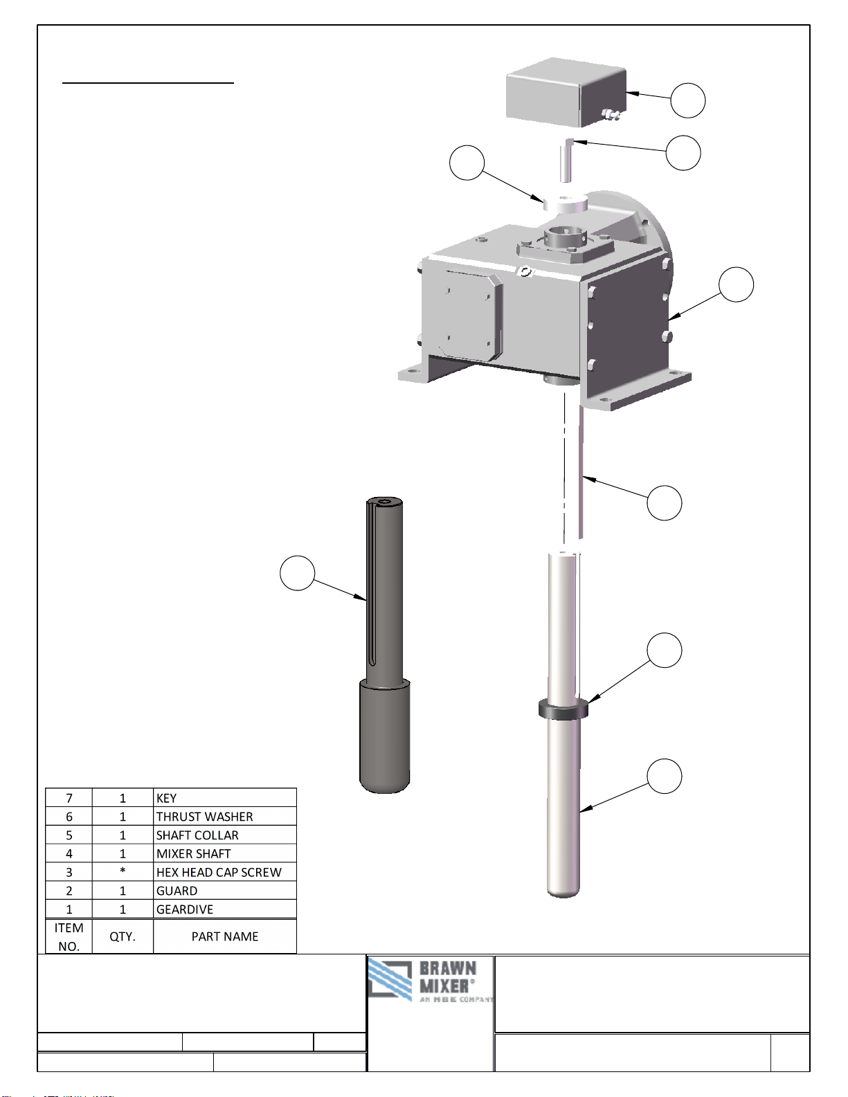
Shaft and Impeller Assembly...................................2 & 3
Start-Up......................................................................... 4
Electric Motors..........................................................4 - 6
Maintenance/Lubrication ............................................... 7
Storage.......................................................................... 8
Gearbox Features ......................................................... 8
Gearbox Features Drawing........................................... 9
Warranty...................................................................... 10
SAFETY
The precautions mentioned in this manual are not
intended to cover all hazards that may exist in a plant or
on this equipment. Using safety mechanisms requires
the constant attention of everyone in the vicinity of this
(or any) equipment.
A plant and the related equipment are only as safe as the
personnel are safety-minded. Proper equipment
maintenance and the use of personal safety devices will
contribute as much toward safety as will any number of
mechanical safety devices.
WARNING
To assure maximum safety, optimum performance,
and to gain knowledge of the product, it is essential
that you or any other operator of this equipment read
and understand the contents of this manual before
the mixer is operated.
Installation, operation and maintenance must be
performed only by qualified personnel.
Do not operate this equipment unless all safety
devices are installed and working properly. Check all
devices prior to starting the equipment.
Disconnect and lock out electrical power before
installing or servicing the mixer.
Do not touch rotating parts (keep all guards and
safety devices installed while operating).
Develop a safety checklist for this equipment and
perform regular maintenance to ensure continued
and proper operation. Develop a safety checklist for
this equipment and perform regular maintenance to
ensure continued and proper operation.
Do not make any field changes or modifications
without reviewing the change with your BRAWN
sales representative or the BRAWN Customer
Service Department.
CUSTOMER SERVICE
Mixer Model #........................................... BWG-SERIES
Mixer Serial #_________________________________
Contact:
Customer Service............................... 616/399-5600
E-Mail ................................brawn@brawnmixer.com
You have received a quality engineered and
manufactured BRAWN Mixer. We value your business,
and we will strive to provide you with the proper service
and equipment to meet your needs.
The information contained in this BRAWN Mixer
Operator's Manual is designed to assist you in putting
your BRAWN Mixer into operation without further delay.
Please read the entire manual before attempting to
start your mixer. If you have any further questions or if,
by some chance, there are some missing components,
contact your BRAWN Mixer Representative or the factory
immediately.
We welcome your comments and suggestions
concerning any BRAWN Mixer product. Please direct
these comments in writing to the National Sales Manager
at BRAWN Mixer, located in Holland, Michigan. To
expedite troubleshooting service, please make your initial
contact through your BRAWN Mixer Representative. If,
for whatever reason, your representative cannot be
reached and you have an emergency condition, please
call us directly at 616/399-5600 and ask for the
Customer Service Department.
Remember, you are backed by your BRAWN Mixer
Technical representative and the factory support team.
We are here to assist you; let us know how we can be of
help.

BWG-SERIES OPERATION & MAINTENANCE MANUAL
12838 Stainless Drive, Holland, MI 49424 Phone: 616/399-5600 Fax 616/399-3084
Copyright 2018 BRAWN Mixer www.BRAWNMIXER.com Page 2 of 11
11/27/2018
INITIAL INSPECTION
1. Upon receipt of your Brawn Mixer, check for possible
shipping damage. Report any damage immediately
to the carrier and to Brawn Mixer.
2. All Brawn Mixers are shipped with the shaft and
impeller(s) disassembled from the drive assembly.
3. Storage: Mixers should not be stored near vibrating
machinery to avoid damage to the bearings. Store
mixers as packaged by the factory. For longer
storage periods, consult factory. If electric motors
have been subjected to humid conditions, check the
insulation resistance between phase and mass and
between the different phases. The resistance should
not be less than 100 megohms. If the resistance is
less, please consult the factory. If mixer is stored for
more than a year, the condition of the gear lubricant
should be checked before the mixer is put in
operation (see lubrication instructions).
INSTALLATION
[REFER TO ASSEMBLY / DIMENSION DRAWING]
Refer to the mixer installation / assembly drawing for
important mounting structure design, assembly,
mounting and dimensional data.
1. Install the mixer drive on the mounting structure and
secure with properly-sized, Grade 5 or better
hardware. Torque the hardware as recommended in
TABLE 1.
2. Install mixer shaft and impeller(s) (refer to shaft and
impeller assembly section).
TABLE 1: RECOMMEND TORQUE VALUES
HARDWARE
SIZE
TORQUE VALUES (FOOT POUNDS)
STANDARD GRADE 2
& 300 SERIES
STAINLESS
HIGH STRENGTH
GRADES 5 & 8
3/8-16
17
27
7/16-14
27
40
1/2-13
40
65
9/16-12
65
90
5/8-11
85
125
3/4-10
135
225
7/8-9
145
365
1-8
210
545
BOLT-TIGHTENING RECOMMENDATIONS:
Inadequately or improperly tightened hardware can
loosen, due to vibration during mixer operation. This can
result in reduced mixer life or damage to equipment.
Recommended torque values for tightening all in-tank
and mounting hardware are listed in TABLE 1. These
average torque values should be considered only as a
guide and not as absolute values.
SHAFT & IMPELLER ASSEMBLY
If an optional rigid shaft coupling is furnished, connect
the mixer shaft and rigid driveshaft couplings by carefully
engaging the shaft rabbeted faces and installing the
mounting hardware. Be careful not to damage the
coupling faces or rabbets, as this can cause excessive
shaft run-out that will affect the life of the mixer
Proper hollow output shaft installation is shown in
FIGURE 1, PAGE 3.
1. Inspect the shaft surface for evidence of damage
and repair, if required, before installing the shaft into
hollow output shaft or connecting to flanged
coupling.
2. Attach the shaft collar (Item 5) to the mixer shaft
(Item 4).
3. Place the key (Item 7) on the mixer shaft and slide
the mixer shaft into the hollow output shaft on the
gear drive (Item 1).

BWG-SERIES OPERATION & MAINTENANCE MANUAL
12838 Stainless Drive, Holland, MI 49424 Phone: 616/399-5600 Fax 616/399-3084
Copyright 2018 BRAWN Mixer www.BRAWNMIXER.com Page 3 of 11
11/27/2018
SHAFT & IMPELLER ASSEMBLY,
Continued
4. Place the thrust washer (Item 6) over the hollow
output shaft on the top of the gear drive. Attach the
hex head cap screw (Item 3) through the thrust
washer (Item 6) and into the mixer shaft. Torque the
Grade 5 hex head cap screw to the recommended
value in Table 1.
5. Attach the guard (Item 2) on the top of the gear
drive.
FIGURE 1: SHAFT INSTALLATION
For Installing Impellers without a Hook Key
Inspect the impeller bore and shaft surface for evidence
of damage and repair, if required, before installing the
impeller(s) on the shaft. Install the impeller(s) on the
mixer shaft by carefully sliding the impeller hub over the
shaft to its proper location and tighten the set screws. It
is recommended that the shaft be spotted with a drill
point at the setscrew locations to prevent loosening of
the impeller(s).
For Installing Impellers with a Hook Key
To install the impeller on the shaft, slide the impeller hub
over the mixer shaft, place the hook key in position,
lower the hub over the hook key and tighten the set
screw. The set screw must seat in the countersunk hole
in the hook key. Proper impeller mounting is illustrated in
FIGURE 2.
FIGURE 2: IMPELLER MOUNT WITH HOOK KEY
If an axial flow impeller of bolt together construction is
used, blades should be bolted to the bottom of the
impeller hub ears as shown in FIGURE 3.
FIGURE 3: TYPICAL AXIAL FLOW
IMPELLER ASSEMBLY (A45 SHOWN)

BWG-SERIES OPERATION & MAINTENANCE MANUAL
12838 Stainless Drive, Holland, MI 49424 Phone: 616/399-5600 Fax 616/399-3084
Copyright 2018 BRAWN Mixer www.BRAWNMIXER.com Page 4 of 11
11/27/2018
START UP
1. All units are lubricated before shipment. The
lubricant level should be checked with the unit
mounted in its correct operating position. Lubricant
should be added or removed to bring it to the correct
level.
2. Connect the motor in accordance with the motor
nameplate. The motor starter should incorporate
overload protection. Before operating the mixer, jog
the motor and observe mixer shaft rotation. Proper
rotation is clockwise, as viewed from the top, unless
otherwise noted.
3. Check all bolts and fasteners for tightness. It is good
maintenance practice to recheck all bolts after two
weeks of operation and periodically thereafter. Refer
to TABLE 1 for recommended torque values.
4. Do not attempt to start mixer with impellers buried in
solids or solidified liquids.
CAUTION
Do not operate mixer with the tank empty or the lowest
impeller submerged with less than ½ of the impeller
diameter of liquid above it. Damage to the mixer and/or
mounting structure may result.
ELECTRIC MOTORS
This equipment contains HAZARDOUS VOLTAGES,
ROTATING PARTS AND HOT SURFACES. SEVERE
PERSONAL INJURY OR PROPERTY DAMAGE CAN
RESULT IF SAFETY INSTRUCTIONS ARE NOT
FOLLOWED. Only qualified personnel should work on or
around this equipment after becoming thoroughly familiar
with all warnings, safety notices, and maintenance
procedures contained herein. The successful and safe
operation of this equipment is dependant upon proper
handling, installation, operation and maintenance.
WARNING
Explosion-proof motors-these motors are constructed to
comply with the U.L. Label Service Procedure Manual.
When repairing and reassembling a motor that has an
underwriter’s label, it is imperative that the unit be
reinspected and:
1. All original fits and tolerance be maintained.
2. All plugs and hardware be securely fastened.
3. Any parts replacements, including hardware, be
accurate duplicates of the originals.
Repair work on explosion-proof motors can only be done
by the original manufacturing or U.L. certified shops.
Violations of any of the above items will invalidate the
significance of the U.L. Label.
STORAGE
Motors must be stored in a clean, dry, well ventilated
location free from vibration and rapid or wide
temperature variations. If the unit is to be stored longer
than three months, consult factory. Ball bearing motors
are shipped from the factory properly lubricated and
ready to operate. When in storage, the motor shaft must
be turned several rotations every month and bearings
relubricated every year. On non-explosion-proof TEFC
motors, a removable plug in the bottom of the frame or
housing permits removal of accumulated moisture. Drain
regularly if storage atmosphere results in formation of
condensation.

BWG-SERIES OPERATION & MAINTENANCE MANUAL
12838 Stainless Drive, Holland, MI 49424 Phone: 616/399-5600 Fax 616/399-3084
Copyright 2018 BRAWN Mixer www.BRAWNMIXER.com Page 5 of 11
11/27/2018
ELECTRIC MOTORS, Cont.
INSTALLATION
Installation must be handled by qualified service or
maintenance personal.
OPERATION
CAUTION
Repeated trial starts can overheat the motor and may
result in motor burnout. If repeated trial starts are made,
allow sufficient time between trials to permit heat to
dissipate from windings and rotor to prevent overheating.
Starting currents are several times running currents, and
heating varies as the square of the current.
After installation is completed, but before motor is put in
regular service, make an initial start as follows:
1. Check motor starting and control device
connections against wiring diagrams.
2. Check voltage, phase, and frequency of line circuit
(power supply) against motor nameplate.
3. If possible, remove external load (disconnect drive)
and turn shaft by hand to ensure free rotation. This
may have been done during installation procedure;
if so, and conditions have not changed since, this
check may not be necessary.
a. If drive is disconnected, run motor at no load
long enough to be certain that no unusual
conditions develop. Listen and feel for
excessive noise, vibration, clicking, or
pounding. If present, stop motor immediately.
Investigate the cause and correct before
putting motor in service.
b. If drive is not disconnected, interrupt the
starting cycle after motor has accelerated to
low speed. Carefully observe for unusual
conditions as motor coasts to a stop.
4. When checks are satisfactory, operate at minimum
load and look for unusual condition. Increase load
slowly to maximum. Check unit for satisfactory
operation.
CAUTION
Guard against overloading. Overloading causes
overheating and overheating means shortened insulation
life. A motor subjected to a 10°C temperature rise above
the maximum limit for the insulation may cause the
insulation life to be reduced by 50%. To avoid
overloading, be sure motor current does not exceed
nameplate current when nameplate voltage is applied.
Electric motors operating under normal conditions
become quite warm. Although some places may feel hot
to the touch, the unit may be operational within limits.
Use a thermocouple to measure winding temperature.
The total temperature, not the temperature rise, is the
measure of safe operation. Investigate the operating
conditions if the total temperature measured by a
thermocouple placed on the windings exceeds:
230°F (110°C) for class “B” insulation
275°F (135°C) for class “F” insulation
302°F (150°C) for class “H” insulation
VOLTAGE REGULATION
Motors will operate successfully under the following
conditions of voltage and frequency variation, but not
necessarily in accordance with the standard established
for operation under rated conditions:
1. When the variation in voltage does not exceed
10% above or below normal, with all phases
balanced.
2. When the variation in frequency does not exceed
5% above or below normal.
3. When the sum of the voltage and frequency of the
voltage does not exceed 10% above or below
normal (provided the frequency variation does not
exceed 5%).
MAINTENANCE
Failure to properly maintain the equipment can result in
severe personal injury and product failure. The
instructions contained herein should be carefully
reviewed, understood and followed. The following
maintenance procedures should be performed regularly:
1. Bearing lubrication (When regreaseable bearings
are supplied)
2. Insulation resistance check
3. Cleaning

BWG-SERIES OPERATION & MAINTENANCE MANUAL
12838 Stainless Drive, Holland, MI 49424 Phone: 616/399-5600 Fax 616/399-3084
Copyright 2018 BRAWN Mixer www.BRAWNMIXER.com Page 6 of 11
11/27/2018
ELECTRIC MOTORS, Cont.
This checklist does not represent an exhaustive survey
of maintenance steps necessary to ensure safe
operation of the equipment. Particular applications may
require further procedures
Dangerous voltages are present in the equipment which
can cause severe personal injury and product failure.
Always de-energize and ground the equipment before
maintenance. Maintenance should be performed only by
qualified personal.
The use of unauthorized parts in the repair of the
equipment, tampering by unqualified personal, or
removal or alteration of guards or conduit covers will
result in dangerous conditions which can cause severe
personal injury or equipment damage. Follow all safety
instructions contained herein.
BEARING LUBRICATION
(When regreaseable bearings are supplied)
CAUTION
Do not lubricate motor while in operation, since excess
grease will be forced through the bearings and into the
motor before it will force its way out the drain plug.
Excess grease accumulation on windings reduces
insulation life.
Prior to shipment, motor bearings are lubricated with the
proper amount and grade to provide six months of
satisfactory service under normal operation and
conditions.
For best results, grease should be compounded from a
polyurea base and a good grade of petroleum oil. It
should be of No. 2 consistency and stabilized against
oxidation. Operating temperature ranges should be from
-15°F to +250°F for class B insulation, and to +300°F for
class F and H. Most leading oil companies have special
bearing greases that are satisfactory.
Relubricate bearings every six months (more often if
conditions require), as follows:
1. Stop the motor. Lock out the switch.
2. Thoroughly clean off pipe plugs and remove
from housings.
3. Remove hardened grease from drains with stiff
wire or rod.
4. Add grease to inlet with hand gun until small
amount of new grease is forced out drain.
5. Remove excess grease from ports, replace inlet
plugs, and run motor ½ hour before replacing
drain plug.
6. Put motor back in operation.
INSULATION RESISTANCE
Check insulation resistance periodically. Any approved
method of measuring insulation resistance may be used,
provided the voltage across the insulation is at a safe
value for the type and condition of the insulation. A hand
crank megger of not over 500 volts is the most
convenient and safest method. Standards of the Institute
of Electrical and Electronics Engineers, Inc., recommend
that the insulation resistance of the stator windings at 75°
C, measured at 500 volts dc, after one minute should not
be less than:
Rated Voltage of Machine + 1000
=
Insulation Resistance
1000
in Megohms
This formula is satisfactory for most checks. For more
information, see IEEE Standard No. 43 “Recommended
Practice for Insulation Resistance Testing of AC Rotating
Machinery.”
CLEANING
WARNING
Do not attempt to clean the motor while it is operating.
Contact with rotating parts can cause severe personal
injury or property damage. Stop the motor and lock out
switch before cleaning.
The motor exterior must be kept free of oil, dust, water,
and chemicals. For fan cooled motors, it is particularly
important to keep the air intake openings free of foreign
material. Do not block air outlet or inlet.
On non-explosion-proof TEFC motors, a removable plug
in the bottom center of the motor frame or housing
permits removal of accumulated moisture. Drain
regularly.

BWG-SERIES OPERATION & MAINTENANCE MANUAL
12838 Stainless Drive, Holland, MI 49424 Phone: 616/399-5600 Fax 616/399-3084
Copyright 2018 BRAWN Mixer www.BRAWNMIXER.com Page 7 of 11
11/27/2018
MAINTENANCE / LUBRICATION
Gear units should have the oil changed every 2,500
hours or six months. If synthetic lubricant is used, it
should be changed every 6,000 hours or 2 years. For
adverse operating conditions, the interval should be
shorter. DO NOT MIX SYNTHETIC AND MINERAL
BASE OILS. Units should be checked periodically for
increased noise, surface temperature, vibration, shaft
movement and amperage draw. Units with inspection
covers should not be operated with the inspection cover
removed.
CAUTION
Oil should be changed more often if reducer is used in a
severe environment. (i.e. dusty, humid)
TABLES 2 and 3offer suggestions on the viscosity and
manufacturers of recommended lubricants. Some gear
lubricants contain E.P. additives that can be corrosive to
gear bronze. Avoid lubricants that are compounded with
sulfur and/or chlorine.
Always check for proper oil level after filling. Capacities
vary somewhat with model and mounting position. Oil
should rise to bottom edge of level hole. Do Not Overfill.
TABLE 2: APPROXIMATE OIL CAPACITY FOR
GEAR DRIVES
GEARBOX MODEL
PINTS
218
1
220
1.5
224
1.75
226
3
230
3.75
232
5
242
8
252
13.5
Reducers ordered from the factory will be filled to the
proper level with lubricant. After the installation of the
breather plug, the unit is ready for use. Before installing
the breather plug, refer to the instruction tag and
determine the proper position according to reducer
mounting specifications.
CAUTION
In the Food and Drug Industry (including animal food),
consult the lubrication supplier for recommendation of
lubricants which are acceptable to the Food and Drug
Administration and/or other authoritative bodies having
jurisdiction. Factory supplied oil is not suitable for these
applications or this industry.
To assist you in the proper selection of replacement
lubricant, we recommend the following oils for the
ambient temperatures specified.
TABLE 3: RECOMMENDED LUBRICANTS
MANUFACTURER
30
°
TO 100
°
F
AMBIENT
TEMPERATURE
AGMA COMPOUND
NO. 7
50
°
TO 125
°
F
AMBIENT
TEMPERATURE
AGMA COMPOUND
NO. 8
Amoco Oil Co.
Worm Gear Oil
Cylinder Oil #680
Chevron USA, Inc.
Cylinder Oil #460X
Cylinder Oil #680X
Exxon Co. USA
Cylesstic TK-460
Cylesstic TK-680
Gulf Oil Co.
Senate 460
Senate 680D
Mobil Oil Corp.
600W Super
Cylinder
Extra Hecla Super
Shell Oil Co.
Valvata Oil J460
Valvata Oil J680
Sun Oil Co.
Gear Oil 7C
Gear Oil 8C
Texaco
Honor Cylinder Oil
650T Cylinder Oil
Union Oil Co. Steaval A
Worm Gear Lube
140
Note: For Temperature ranges not shown and synthetic
lubrication, contact factory.

BWG-SERIES OPERATION & MAINTENANCE MANUAL
12838 Stainless Drive, Holland, MI 49424 Phone: 616/399-5600 Fax 616/399-3084
Copyright 2018 BRAWN Mixer www.BRAWNMIXER.com Page 8 of 11
11/27/2018
STORAGE
Units shipped from Brawn Mixer are intended to be used
within 30 days after receipt and presumed to be stored
indoors in a heated building. Store mixers as packaged
by the factory. If you intend storing units under adverse
conditions or for a long period of time, special storage
precautions will be necessary.
1. Store in a sheltered area away from chemical vapors or
steam.
2. Cover.
3. Do not store in sunlight or near high heat.
4. Spray oil on exposed shafts and seals. Remove oil on
start-up.
5. Rotate output shaft 360º every 3-4 weeks.
6. Mixers should not be stored near vibrating machinery
to avoid damage to the bearings.
7. If electric motors have been subjected to humid
conditions, check the insulation resistance between
phase and mass and between the different phases.
The resistance should not be less than 100
megohms. If the resistance is less, please consult
the factory
BWG GEARBOX FEATURES
[SEE FIGURE ON PAGE 9]
1. Rugged Cast Iron Housings provide superior
strength and rigidity.
Generous Oil Capacity assures lower operating
temperatures and maximum gear, bearing and seal
life.
2. Hardened and Precision-Ground Worms are cut
integral with the shaft. High helix angles provide the
ultimate in efficiency and torque capacity.
3. Cast Iron Bearing Covers on the input shaft provide
greater reliability when subjected to high start-up or
reversing loads.
4. Tapered Roller Bearings provide greater overhung
load and thrust capability, ensuring maximum life.
5. Chill-Cast Bronze Gears give you the long, trouble-
free life and high quality you expect from Brawn
Mixer drives.
6. Output Oil Seal keeps the lubricant in, contaminants
out. Maintenance costs are reduced.
7. Alloy Steel Output Shafts provide extra strength for
your rugged applications.
LUBRICATION
Splash Lubrication provides positive protection for
gears and bearings.
Splash Guards are furnished to prevent oil from leaking
through the vent.
MIXER NAMEPLATE

BWG-SERIES OPERATION & MAINTENANCE MANUAL
12838 Stainless Drive, Holland, MI 49424 Phone: 616/399-5600 Fax 616/399-3084
Copyright 2018 BRAWN Mixer www.BRAWNMIXER.com Page 9 of 11
11/27/2018
BWG GEARBOX FEATURES

BWG-SERIES OPERATION & MAINTENANCE MANUAL
12838 Stainless Drive, Holland, MI 49424 Phone: 616/399-5600 Fax 616/399-3084
Copyright 2018 BRAWN Mixer www.BRAWNMIXER.com Page 10 of 11
11/27/2018
* Recommended parts for gearbox rebuild
ITEM #
DESCRIPTION
1
Gear Housing
5
Input Cover
6
*O-Ring
7
Hex Head Cap Screw
10
*Input Bearing
15
*O-Ring
16
*Output Cover Gasket (as required)
19
Hex Head Cap Screw
26
Input Cover
27
*Input Oil Seal
30
Double Input Shaft (or #45 per model)
40
Quill Motor Flange
41
*Input Oil Seal
42
Hex Head Cap Screw
43
Retaining Ring - Shaft
44
Retaining Ring - Housing
45
Quill Input Shaft (or #30 per model)
50
Gear Housing
51
*Output Cover Gasket (as required)
52
*Output Oil Seal
53
*Output Bearing
54
Gear Spacer
55
Output Shaft
56
Setscrew
57
Gear Key
58
Output Gear

BWG-SERIES OPERATION & MAINTENANCE MANUAL
12838 Stainless Drive, Holland, MI 49424 Phone: 616/399-5600 Fax 616/399-3084
Copyright 2018 BRAWN Mixer www.BRAWNMIXER.com Page 11 of 11
11/27/2018
WARRANTY
WARRANTY: All equipment or parts covered by this
manual are guaranteed free from defective material and
workmanship for a period of twelve (12) months from
date of shipment, under normal use and service. This
warranty does not cover failure of normal wear parts
unless the failure of such part has resulted from
defective material and workmanship. BRAWN Mixer will
repair or replace, at its option, any equipment which has
been found to be defective and is within the warranty
period, provided that the equipment is shipped, with
previous factory authorization, freight prepaid, to
BRAWN's plant in Holland, Michigan, USA. All return
shipments are made FOB BRAWN's factory. BRAWN is
not responsible for removal, installation, or any other
incidental expenses incurred in shipping the equipment
to or from BRAWN. In the case of components
purchased by BRAWN Mixer and incorporated in the
equipment, the component manufacturer's guarantee
shall apply. NOTE: Any modifications or corrective work
done to the equipment which were not specifically
authorized in writing by BRAWN Mixer shall void this
limited warranty, and BRAWN Mixer shall accept no
liability for any of the corrective work or expenditures
which were conducted without their prior, written
authorization. BRAWN Mixer shall not be held liable for
any further cost, expense, or labor to replace equipment
or replaceable parts, or indirect or consequential
damages.
With the exceptions of the limited warranty set out
above, there are no other understandings, agreements,
representatives, or warranties implied (including any
regarding the merchant-ability or fitness for a particular
purpose), not specified herein, respecting this agreement
or equipment, hereunder. This contract states the entire
obligation of BRAWN Mixer in connection with this
transaction.
SHOULD WE MAKE A MISTAKE...
BRAWN Mixer's
Direct Returns Policy
To ensure proper handling of your return, please take a
moment to read the following:
ALL returns require a RETURN GOODS
AUTHORIZATION (RGA) NUMBER. We are unable
to process your return or issue proper credit without
an approved RGA number.
ALL returns must be COMPLETE, including all
original warranties, manuals, documentation and
packaging.
ALL product must be received within 14 days of
issuing an RGA number.
How to Return Product
You must have a RETURN GOODS AUTHORIZATION
(RGA) number before you return any product to BRAWN
Mixer. To obtain this number, call 616/399-5600 and ask
for Customer Service. Be sure to have available the
following information:
your order number
the BRAWN product serial number
the part number and description of the product
the reason for the return
♦I M P O R T A N T ♦
The Return Goods Authorization number must be written
clearly on all boxes being returned. C.O.D. shipments
will not be accepted.

– THIS PAGE IS INTENTIONALLY LEFT BLANK –

– THIS PAGE IS INTENTIONALLY LEFT BLANK –

– THIS PAGE IS INTENTIONALLY LEFT BLANK –

Table of contents
Other NBE Mixer manuals
Popular Mixer manuals by other brands

Behringer
Behringer Europower PMH518M user manual

Altec Lansing
Altec Lansing 1684A SIGNAL PROCESSING Specifications

Witeg
Witeg Wisd WiseStir HT-AX Series operating manual

Belle Group
Belle Group TBE-130 Operator's manual

Panasonic
Panasonic WJMX50 - MIXER operating instructions

Kogan
Kogan KAHTNSNDMIX user manual