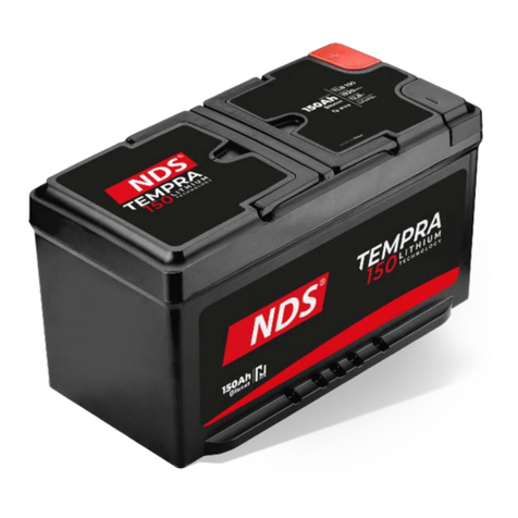
NDS Dometic TEMPRA TLB100 User manual

POWER & CONTROL
TEMPRA
TLB100, TLB120, TLB150, TLB100F, TLB120F, TLB150F
EN Battery
Operating manual..........................................8
DE Batterie
Bedienungsanleitung....................................20
FR Batterie
Manuel d’utilisation...................................... 32
ES Batería
Instrucciones de uso.....................................44
PT Bateria
Manual de instruções................................... 56
IT Batteria
Istruzioni per l’uso........................................68
NL Accu
Gebruiksaanwijzing......................................80
DA Batteri
Betjeningsvejledning....................................92
SV Batteri
Bruksanvisning........................................... 104
NO Batteri
Bruksanvisning............................................116
FI Akku
Käyttöohje................................................. 128
PL Akumulator
Instrukcja obsługi........................................140
SK Batéria
Návod na obsluhu...................................... 153
CS Baterie
Návod k obsluze........................................ 165
HU Akkumulátor
Használati utasítás.......................................177
HR Akumulator
Upute za rukovanje.....................................189
TR Akü
Kullanma Kılavuzu....................................... 201
SL Baterija
Navodilo za uporabo.................................. 213
RO Baterie
Instrucţiuni de operare................................225
BG Акумулатор
Инструкция за експлоатация.......................237
ET Aku
Kasutusjuhend........................................... 249
EL Μπαταρία
Οδηγίες χειρισμού.................................... 261
LT Akumuliatorius
Naudojimo vadovas................................... 274
LV Akumulators
Lietošanas rokasgrāmata............................. 286

EN
List of Figures
1
5
4
3
2
2
3
1
1

EN
2
1
1
2

EN
1 2 3 4 5 6 78
O
N
1
1
3

EN
1 2 3 4 5 6 78
O
N
1
3
4
4
2
1 2 3 4 5 6 78
O
N
1
3
2
4

EN
1 2 3 4
5 6
7
8
O
N
1
3
2
5

EN
N-BUS Live
House Battery
13,4 V 0,0 A
0,0 A
0,0 A
Sun Control DC-DC
Stand By Stand By
85 %
N-BUS Live
House Battery
13,4 V 0,0 A
0,0 A
0,0 A
Sun Control DC-DC
Stand By Stand By
85 %
Language
MYUSERNAME
Date and time
Silent mode
Charging profile
Battery
Solar panels
Bluetooth®
N-BUS
RESET PASSWORD
BATTERY SWITCH
DISCONNECT
Bluetooth®
NDS-TLB150F
Device:
1
2
3
6

Copyright
© 2023 Dometic Group. The visual appearance of the contents of this manual is protected by copyright and design
law. The underlying technical design and the products contained herein may be protected by design, patent or be
patent pending. The trademarks mentioned in this manual belong to Dometic Sweden AB. All rights are reserved.

EN
English
1Important notes..............................................................................................................................8
2Explanation of symbols....................................................................................................................8
3Safety instructions...........................................................................................................................9
4Scope of delivery............................................................................................................................9
5Intended use................................................................................................................................ 10
6Target group.................................................................................................................................10
7Technical description..................................................................................................................... 10
8Installation....................................................................................................................................10
9Configuring the battery..................................................................................................................12
10 Connecting batteries in parallel.......................................................................................................13
11 Wire and fuse sizing.......................................................................................................................14
12 Operation.................................................................................................................................... 14
13 Cleaning and maintenance.............................................................................................................16
14 Storing.........................................................................................................................................16
15 Troubleshooting............................................................................................................................16
16 Disposal.......................................................................................................................................17
17 Warranty...................................................................................................................................... 18
18 Technical data...............................................................................................................................18
1 Important notes
Please read these instructions carefully and follow all instructions, guidelines, and warnings included in this product manual in order to ensure that you install, use, and maintain
the product properly at all times. These instructions MUST stay with this product.
By using the product, you hereby confirm that you have read all instructions, guidelines, and warnings carefully and that you understand and agree to abide by the terms and
conditions as set forth herein. You agree to use this product only for the intended purpose and application and in accordance with the instructions, guidelines, and warnings as
set forth in this product manual as well as in accordance with all applicable laws and regulations. A failure to read and follow the instructions and warnings set forth herein may
result in an injury to yourself and others, damage to your product or damage to other property in the vicinity. This product manual, including the instructions, guidelines, and
warnings, and related documentation, may be subject to changes and updates. For up-to-date product information, please visit documents.dometic.com.
2 Explanation of symbols
WARNING!
Indicates a hazardous situation that, if not avoided, will result in death or serious injury.
CAUTION!
Indicates a hazardous situation that, if not avoided, could result in minor or moderate injury.
NOTICE!
Indicates a hazardous situation that, if not avoided, could result in minor or moderate injury.
8

EN
Note Supplementary information for operating the product.
3 Safety instructions
WARNING! Failure to obey these warnings could result in death or serious injury.
• In event of fire, use a fire extinguisher which is suitable for electrical device.
• Do not operate the device if it is visibly damaged.
CAUTION! Failure to obey these warnings could result in death or serious injury.
• Installation, assembly, and wiring as well as all other work may only be performed by qualified elec-
trical specialists. Inadequate repairs may cause serious hazards.
• Installation in potentially explosive areas such as rooms with inflammable liquids or gases is not per-
mitted.
• Do not install or keep the device near flames or other heat sources (heating, direct sunlight, gas
ovens etc.).
• Children shall not play with the appliance.
• This appliance can be used by children aged from 8 years and above and persons with reduced
physical, sensory or mental capabilities or lack of experience and knowledge if they have been giv-
en supervision or instruction concerning use of the appliance in a safe way and understand the haz-
ards involved.
NOTICE! Indicates a situation that, if not avoided, can result in property damage.
• Check that the voltage specification on the data plate corresponds to that of the energy supply.
• Never immerse the device in water.
• Protect the device and cables against heat and moisture.
• Do not expose the device to rain.
• Make sure that the mounting surface is capable of supporting the weight of the device.
• Lay the cables so that they cannot be tripped over or damaged.
• Use ductwork or cable ducts if it is necessary to lay cables through metal panels or other panels with
sharp edges.
4 Scope of delivery
Description Quantity
Battery 1
Red terminal protection cap 1
Black terminal protection cap 1
Operating manual 1
9

EN
5 Intended use
The battery is intended to provide energy to the appliances and equipment in a motorhome. The battery is intended
to be used with 12 V electrical systems.
This product is only suitable for the intended purpose and application in accordance with these instructions.
This manual provides information that is necessary for proper installation and/or operation of the product. Poor in-
stallation and/or improper operating or maintenance will result in unsatisfactory performance and a possible failure.
The manufacturer accepts no liability for any injury or damage to the product resulting from:
• Incorrect assembly or connection, including excess voltage
• Incorrect maintenance or use of spare parts other than original spare parts provided by the manufacturer
• Alterations to the product without express permission from the manufacturer
• Use for purposes other than those described in this manual
Dometic reserves the right to change product appearance and product specifications.
6 Target group
The electrical power supply must be connected by a qualified electrician who has demonstrated skill and
knowledge related to the construction and operation of electrical equipment and installations, and who
is familiar with the applicable regulations of the country in which the equipment is to be installed and/or
used, and has received safety training to identify and avoid the hazards involved.
7 Technical description
• The battery is manufactured with Lithium (LiFePO4) technology and employs high density power (HDS) cells.
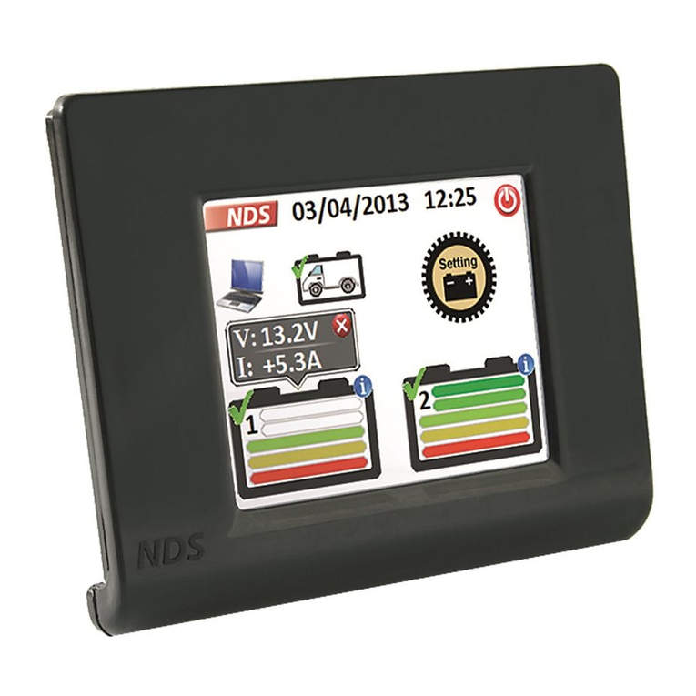
• The battery is equipped with N-BUS communication protocol that allows all devices (equipped with the same
protocol) to be connected in a single energy network. With the optional display or the mobile phone applica-
tion, the connected devices can be contolled, monitored and their firmware can be updated.
• The battery features an internal battery management system (BMS) to automatically regulate the charge input
to the battery.
• TLB100F, TLB120F and TLB150F models: heated versions of the battery designed to withstand low tempera-
tures, as low as -30 °C.
• The battery is equipped with a multicolor status LED.
• The battery features Bluetooth® BLE 5.0 technology for smartphone connectibility.
8 Installation
Battery installation
WARNING! Damage hazard
When working around a battery, do not allow tools to bridge the battery terminals or short circuit any part
of the battery.
10

EN
NOTICE! Damage hazard
To prevent damage to the equipment, deactivate all loads and the charger before battery installation.
NOTICE! Damage hazard
Battery cables must not be connected to the battery in reverse polarity, otherwise damage to the device
may occur.
NOTICE! Damage hazard
To prevent damage to the equipment, always connect the positive cable first.
Note The battery can only be installed in the upright position on a horizontal surface.
fig. on page1
1. Remove the terminal protection caps and .
2. Install the battery cables to the corresponding terminal using appropriate fasteners .
3. To ensure a secure electrical contact, tighten the fasteners to the end of the threads, without using excessive
force.
4. Install the terminal protection caps and .
5. If possible, secure the battery to the floor to avoid unexpected movements during the journey.
Note It is also allowed to connect automotive terminal clamps with M8 screws and appropriate washers.
NOTICE! Damage hazard
Never connect multiple batteries in series.
Display installation (Optional)
fig. on page1
1. Slide the bracket down .
2. Tilt the bracket away from the display .
3. Slide the bracket up .
fig. on page2
4. Using the bracket, mark the screw holes and the cable passage hole on the mounting surface.
5. Drill the screw holes and the cable passage hole .
6. Pull the communication cable through the passage hole both on the mounting surface and the bracket.
7. Mount the bracket on the mounting surface using the supplied screws.
fig. on page2
8. Connect the connection cable to the display .
9. Mount the display on the bracket.
11

EN
fig. on page3
10. Connect the connection cable to one of the N-BUS connectors .
Note Both N-BUS connectors can be used for connecting the display or another N-BUS device.
Smartphone application installation
To connect to the battery with a Bluetooth® BLE-compatible (v. 4.2 or higher) smartphone, download the
NDS Energy application:
Download the NDS Energy app.
Once switched on, the battery will be visible in the Bluetooth menu of the smartphone with the name
'TLB100xxxxx' where the 'xxxxx' represents the serial number of the battery.
9 Configuring the battery
N-BUS/CI-BUS selection
The battery supports both the native N-BUS protocol and the CI-BUS protocol, shared with other manufacturers.
N-BUS setup (default) Ci-BUS setup
O
N12 3 4 5 6
O
N12 3 45 6
Act on the DIP switches 1 and 4 to select the desired protocol.
Note When CI-BUS protocol is active, the N-BUS will not be detected.
BUS power supply
Both the N-BUS and the CI-BUS can be powered on and off altogether. Switching off the BUS means switching off all
connected devices, such as the display.
12

EN
BUS on (default) BUS off
O
N1 2 3 4 56
O
N1 2 3 4 56
Act on the DIP switch 5 to turn the BUS power supply on or off.
Note
Even if the battery is powered off and the connections to its terminals are disconnected, the BUS power
line remains powered. To interrupt power supply to the BUS line, set DIP switch 5 to off position.
Battery power supply
Battery power on (default) Battery power off
O
N1 2 3 4 56
O
N1 2 3 4 56
Act on the DIP switch 6 to turn the battery on or off.
Note Turning the battery on or off with DIP switch 6 has the same effect as using the On/Off switch but
using the DIP switch 6, being a mechanical switch, provides immediate visual feedback on the on or off
state of the battery.
10 Connecting batteries in parallel
Note To increase the ampere-hour (Ah) capacity, up to four batteries can be connected in parallel.
Connect the batteries in the following order:
fig. on page3
1. Open the connection box of the batteries.
fig. on page4
2. Select the master mode (off) with DIP switch 4 on one of the batteries.
3. Select the slave mode (on) with DIP switch 4 on rest of the batteries.
4. Connect the positive terminals of the batteries.
5. Connect the negative terminals of the batteries.
13

EN
6. Establish the N-BUS network by connecting the batteries with appropriate cables equipped with RJ11 6C/6P
connectors .
11 Wire and fuse sizing
In order to properly dimension wiring and fuses, the distances and loads must be analysed. As it is not possible to
provide a unique figure valid for every application, the following examples are purely indicative.
Maximum wire cross-sectionEstimated maxi-
mum consumption Length ≤2mLength 2m… 4mLength ≥4m
Fuse
20 A (refrigerator,
lights, water pump)
4mm² 6 mm² 10 mm² 40 A
130 A (inverter with
coffee machine, and
hairdryer)
25 mm² 35 mm² 50 mm² 150 A
200 A (inverter with air
conditioner)
35 mm² 50 mm² 70 mm² 200 A
12 Operation
Note Always charge the battery completely before using it to its full potential.
Activation
By factory default setting, the battery is inactive mode. No voltage present at the terminals and to use it, it must be ac-
tivated and switched on.
fig. on page4
1. Push the DIP switch 6 to on position.
2. Press and hold the On/Off switch for 1 second.
The battery will be active when the LED indicator lights up.
Shutting down
The battery can be switched off in four different ways:
• With the display button.
• With the On/Off switch.
• With DIP switch 6.
• With the smartphone application.
fig. on page5
To turn the battery off at the display, press and hold the button until the message "Shutdown" is displayed. The
battery will turn off with the Bluetooth® function remaining active.
14

EN
fig. on page5
To switch off the battery together with the Bluetooth® function using the On/Off switch, press and hold it
for 8 seconds until LED starts flashing in purple.
To switch off the battery with the On/Off switch leaving the Bluetooth® function active, press and hold it for
4 seconds until LED starts flashing in blue.
To deactivate the battery for longer storage, push the DIP switch 6 into off position.
Shutting down by the smartphone application
fig. on page6
1. Tap on the menu icon .
2. Tap on the Bluetooth® icon .
3. Tap on the Battery switch icon .
The battery will switch off after a few seconds, with the Bluetooth® function remaining active.
LED indications
LED indication Description
Green - steady Battery is starting up. No voltage present at the terminals.
Green - flashing Battery is active. Voltage present at the terminals.
Blue - flashing Battery is powering down. Bluetooth® active. No voltage present at the terminals.
Purple - flashing Battery is powering down. Bluetooth® not active. No voltage present at the terminals.
Red - flashing Battery alarm. No voltage present at the terminals.
Orange - flashing Temperature range limit reached. Voltage present at the terminals.
Orange - steady Firmware update.
Off Battery inactive. Bluetooth® active. No voltage present at the terminals.
Charging
When charging the battery with an external charger, observe the following guidelines:
• Use chargers intended for charging lithium (LiFePO4) batteries. Other type of charger will reduce battery life.
• The charger must not perform any desulfation action.
• When using a configurable charger, set the contant current/constant voltage (CC/CV) option with the follow-
ing values:
• Set the end of charge voltage to 14.4 V.
• Set the recommended maximum charging current for the battery.
• The maximum charging voltage should not exceed 14.5 V.
• When the battery is fully charged and the display shows 100% state of charge, disconnect or turn off the charg-
er.
TLB100F, TLB120F and TLB150F models: When the battery is being charged at temperatures below 0 °C, the cell
heating system is activated. The cell heating system uses the charger's energy to power itself and, once the ideal
charging temperature is reached, the heating is switched off and charging begins. If, during charging, the tempera-
ture raises above the permissible range, the internal battery management system (BMS) will limit the charge to pre-
serve battery life.
15

EN
Discharge
The internal battery management system (BMS) protects the electronic system and the battery cells. It supports a
continuous current of 135 A. However, it is possible to use higher currents for a limited time, in accordance with the
following values.
Maximum discharging timeDischarging current
TLB100/TLB100F TLB120/TLB120F TLB150/TLB150F
150 A15 min 20 min 20 min
180 A 2 min 3 min 5 min
200 A 60 s 60 s 150 s
NOTICE! Damage hazard
• Do not discharge the battery over the temperature range of -20 °C… 60 °C.
• If the voltage drops below 10.5 V ± 0.1 V the battery generates an alarm and deactivates the termi-
nals.
13 Cleaning and maintenance
The batteries are maintenance-free.
Occasionally clean the product with a damp cloth.
14 Storing
Before storing, fully charge the battery with a recommended battery charger for 1-2 days.
When the battery is not in use, ensure that the battery voltage does not drop below 12.6 V.
When storing the battery on longer term, completely recharge it every 30 days.
15 Troubleshooting
Problem Possible cause Suggested remedy
Cell voltage high. One or more cells with voltage above
the permitted limit.
Discharge the battery by 3 Ah.
The alarm is deactivated when
the cell voltage returns to normal
operating levels.
Cell voltage low. One or more cells with voltage below
the permitted limit. Connect a battery charger and
turn on the battery by pressing
and holding the On/Off switch
for 1 second. If the voltage of
one or more cells is below the
safety limit, the battery will re-
main on for about 10 seconds
in order to allow the cells to be
charged and then reset.
16

EN
Problem Possible cause Suggested remedy
Temperature problem charging. Internal battery temperature outside
permissible limits. Disconnect the charger for a few
minutes. The alarm is deactivat-
ed if the temperature returns to
normal operating levels.
Temperature problem discharging. Internal battery temperature outside
permissible limits. Avoid discharging the battery for
a few minutes. The alarm is deac-
tivated if the temperature returns
to normal operating levels.
Short circuit. Very high current (greater than 260 A).
Consumer failure. Check that all connected con-
sumers are working properly.
The alarm is deactivated after
approximately 5 seconds. If it
should reactivate (e.g. due to
a short circuit at the poles), the
alarm remains active until the
On/Off switch is pressed.
Overcurrent. Very high current (greater than 180 A).
A consumer has been activated that
draws power exceeding the limit of
the battery.
Disconnect the consumer. The
alarm is deactivated after ap-
proximately 5 seconds.
Battery over voltage. Battery terminal voltage above 16 V.
Faulty charger or wrong type of charg-
er used.
Disconnect the charger. The
alarm is automatically deactivat-
ed when the voltage drops be-
low 15.6 V.
Battery voltage low. Battery terminal voltage below 10.5 V. The voltage at the terminals is
switched off for a few minutes,
and then automatically restored
for a few seconds. The purpose
of this function is to protect the
battery from further discharge by
keeping it switched off for a few
minutes, and at the same time
allowing the battery charger to
detect it.
Battery fault. Internal failure. Contact an authorized service
agent.
16 Disposal
Recycling packaging material: Place the packaging material in the appropriate recycling waste bins wher-
ever possible.
Recycling products with batteries, rechargeable batteries and light sources: Remove any batteries,
rechargeable batteries, and light sources before recycling the product. Return defective or used batteries
to your retailer or dispose of them at collection points. Do not dispose of any batteries, rechargeable bat-
teries, and light sources with general household waste. If you wish to finally dispose of the product, ask
your local recycling center or specialist dealer for details about how to do this in accordance with the ap-
plicable disposal regulations. The product can be disposed free of charge.
17

EN
17 Warranty
The statutory warranty period applies. If the product is defective, please contact the manufacturer's branch in your
country (see dometic.com/dealer) or your retailer.
For repair and warranty processing, please include the following documents when you send in the device:
• A copy of the receipt with purchasing date
• A reason for the claim or description of the fault
Note that self-repair or nonprofessional repair can have safety consequences and might void the warranty.
18 Technical data
TLB100/TLB100F TLB120/TLB120F TLB150/TLB150F
Technology LiFePO4
Nominal voltage 12.8 V DC
Nominal capacity, at 25 °C 100 Ah 120 Ah 150 Ah
Nominal energy, at 25 °C 1280 Wh 1536 Wh 1920 Wh
Number of cells in series 4
Recommended maximum dis-
charge current
100 A 120 A 135 A
Maximum supported discharge
current
200 A / 60 s 200 A / 150 s
End of discharge voltage 10.5 V ± 0.1 V
Recommended maximum charg-
ing current
50 A / 0.5 C 60 A / 0.5 C 75 A / 0.5 C
Maximum supported charging
current
100 A / 1 C 120 A / 1 C 150 A / 1 C
End of charging voltage 14.4 V ± 0.2 V
Number of cycles 80 % DOD 3500
Operating temperature, dis-
charge
– 20… 60 °C
Operating temperature, charge
(TLB100, TLB120 and TLB150)
– 10… 45 °C
Operating temperature, charge
(TLB100F, TLB120F and TLB150F)
– 30… 45 °C
Storage temperature – 20… 45 °C
Self-discharge ≤5% / month
Maximum humidity 95 %
Pole connection size M8
Weight 12.8 kg 13.5 kg 16.1 kg
Dimensions (W x D x H) 341 mm× 190 mm× 176 mm
18
This manual suits for next models
5
Table of contents
Languages:
Other NDS Camera Accessories manuals