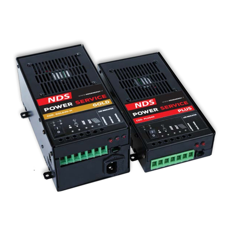
NDS Smart-in SM Series User manual

Smart-in
DC/AC
POWER CONVERTER
SM-Series and SP-Series
User Manual
1
EN IT

SUMMARY:
1. INTRODUCTION
2. MODELS
3. IMPORTANT SAFETY INSTRUCTIONS
4. PROTECTION FEATURES
5. MODE OF OPERATION
6. INDICATIONS
7. INTERFERENCE PROBLEMS
8. BATTERY REQUIREMENTS
9. INVERTER MOUNTIN
9.1 INSTALLATION STEPS
9.2 AC LOADS CONNECTION STEPS
10. RATED VS. ACTUAL CURRENT OF LOADS
11. FUSES REPLACEMENT
12. MAINTENANCE
13. TECHNICAL CHARACTERISTICS
14. WARRANTY
2

1. INTRODUCTION:
Smart-in is the new range of inverters designed and developed by NDS, which has
managed to create a series of professional products that reflect their own customers
expectations. hese Inverters have been designed to guarantee the best performance
in terms of safety, efficiency and reliability.
hanks to some special technical and innovative solutions Smart-in inverters are also
suitable for professional use.
Smart-inverters convert the direct current into the alternating current network in the
Modified Sine Wave (Smart-in SM) or Pure Sine Wave (Smart-in SP). his allows the
use of all the standard utilities for the mains (220V) with an accumulator 12V or 24V,
according to the version.
wo product lines are introduced as follows:
- Smart-in SM with Modified Sine Wave output, black and gray.
- Smart in-SP with Pure Sine Wave output, red and gray.
MAIN FEATURES:
✔High efficiency up to 90% and low self-consumption
✔Input with professional connectors
✔Predisposition for remote control ON/OFF
✔he input and output are completely isolated for a greater safety
✔High stability on the entire input voltage range (10V - 15.5V for the 12V
version 20V - 31V for the 24V version)
✔Ultra Low Noise operation with temperature controlled fan speed
he high efficency has been achieved thanks to an innovative circuit solution and by
using professional input connectors that prevent power loss on the main power path.
Input and output circuits are completely isolated by internal transformers, given to the
products a great level of safety.
he innovative circuit solutions adopted inside the Smart-in inverters allow to have a
great efficiency and operational stability over the entire operating input voltage range
with a low self-consumption.
Load and temperature controlled fan cooler, give an ultra low noise operation to the
inverter, that with a small load can work without fan, and also at bigger loads
conditions, the fan speed is controlled by the internal temperature of the inverter so it
can work in the condition as quite as possible. he speed of the fan cooler is
controlled by the entity of the load connected and by the temperature reached by the
device, giving to the inverter the possibility to work in ultra silent mode with utilities
of small entity and instead, with large utilities, to always work with a noise level as
low as possible.
3

2. MODELS:
Smart-in Power Inverter range consists of the following models:
Smart-in SM:
OUTPUT
POWER
12V
Input Voltage
code:
24V
Input Voltage
code:
400W SM-400 SM400-24
600W SM-600 SM600-24
1000W SM-1000 SM1000-24
1500W SM-1500 SM1500-24
Smart-in SP:
OUTPUT
POWER
12V
Input Voltage
code:
24V
Input Voltage
code:
400W SP-400 SP400-24
600W SP-600 SP600-24
1000W SP-1000 SP1000-24
1500W SP-1500 SP1500-24
4

3. IMPORTANT SAFETY INSTRUCTIONS:
his chapter contains important safety and installation instructions for Smart-in SM
and SP series power inverters.
WARNING! Pay attention to handle this device.
Read this manual before installation and use
Device for use in enclosed spaces protected from rain and splashes of
water and liquids in general. he introduction of liquid into the
inverter may result in electric shock.
he inverter contains dangerous substances for the environment, so it
is not allowed the free product disposal, but it is necessary to use the
appropriate collection centers organized by municipalities and regions
or contact the manufacturer directly.
Respecting this rule protects the environment.
Do not use the device in flammable environments where a spark
could cause a fire or the spreading of flames, because the inverter
contains components which tend to produce arcs or sparks.
Do not open the device, electric shock hazard
FIRE AND BURN HAZARD
5

–Do not cover or obstruct the air intake vent openings and/or install in a zero-
clearance
–Do not work in the vicinity of lead-acid batteries. Batteries generate corrosive
gases during normal operation that can damage the inverter. his gas is also
explosive, so it is can be very dangerous.
6

4. PROTECTION FEATURES:
Our Power inverters are equipped with numerous protection features to guarantee
safe and trouble-free operation:
✔Soft Start
✔Protection against overload and shortcircuit
✔Low battery alarm
✔Protection against polarity inversion and overtemperature
Low Battery Alarm
Alerts you if the battery has become discharged to
10.5V or 21V.
Alert is done by an internal Buzzer "beep".
Low Battery Voltage
Shutdown
Shuts the inverter down automatically if the battery
voltage drops below 9.5V or 19V. his feature protects
the battery from being completely discharged.
High Battery Voltage
Shutdown
Shuts the inverter down automatically if the input
voltage rises to 15.5V or 31V.
Over Load Shutdown
he inverter shuts down automatically if the loads
connected to the inverter exceed the inverter operating
limits.
Over Thermal Shutdown he inverter shuts down automatically if its internal
temperature rises above an unacceptable level.
Output Short Circuit
Shutdown
he inverter shuts down automatically if a short circuit
is detected in the circuitry connected to the inverter
output.
Reverse Polarity
Protection
In case of wrong polarity connection, the internal fuse
shall blow out.
Earth Fault Protection
he inverter complies with the standard current leakage
allowance. When large current leakage to earth terminal
occurs, the protection circuit will activate and shut
down the inverter, to avoid the danger of electric shock.
urn off the inverter, unplug the fault AC appliances
and then turn ON again to restart it.
Notes: All protection is automatically recovered.
7

5. MODE OF OPERATION:
Inside the Smart-in inverterS there are 2 main circuit stages, to convert the DC input
voltage to the output AC voltage:
1) First stage consistes of an isolated high frequency DC/DC converter to convert
the input 12V DC (or 24V, according to the version) to an higher voltage up to
330V DC.
2) he final stage consists of an H bridge that convert this DC high voltage in two
possible waveform:
8

6. INDICATIONS:
LED Indicators reen and Red:
he Green LED is ON when Inverter is switched ON and it is operational
he Red LED is ON only to show an alarm condition (Over Load, Over
Heat etc...)
Main Switch with 3 positions:
0 – Switch OFF the device
1 – Switch ON the device
2 – Switch ON/OFF the device from remote controller
USB port with 5V 1.2A output power, only to charge or supply your
tablet, smartphone etc...
AUX/Remote Control port to Switch ON/OFF the device from remote.
Output Outlets to connet and supply your AC Loads.
Plastic flanges to fix the inverter to floor or wall.
Input Power connectors + and – to connect to the 12V or 24V DC
battery bank.
Chassis ground screw connector for protection issue.
Fan holes for cooling issue
9
1
3
2
4
6
5
7
8
9
1
2
3
4
5
6
7
8
9

7. INTERFERENCE PROBLEMS:
Some inexpensive stereo systems may emit a buzzing noise from their loudspeakers
when operated from the inverter. his occurs because the power supply in the audio
system does not adequately filter the modified sine wave produced by the inverter.
he only solution is to use a sound system that has a high quality power supply, or
use a pure sine wave inverter.
When the inverter is operating, it can interfere with television reception on some
channels. If interference occurs, try the following:
–Make sure that the chassis ground screw of the inverter is connected to the
ground system fo your vehicle.
–Make sure that the television antenna provides an adequate signal and the
antenna cable is in good conditions.
–Keep the cables between the battery and the inverter as short as possible, and
twist them together to reduce the radiated emissions.
–Move the television as far away from the inverter as possible.
–Do not operate high power loads with the inverter which the television is on.
10

8. BATTERY REQUIREMENTS:
Battery type and battery size strongly affect the performance of the power inverter.
herefore, you need to identify the type of loads your inverter will be powering and
how much you will be using them between charges. o determine the minimum
battery size that you need to operate appliances, follow these steps:
•Determine the wattage of each appliance and/or tool you will need to
simultaneously operate fromhe inverter. o do this, read the labels on the
requirement to be operated. Usually, power consumption s shown in watts. If it
is shown in amps, multiply by 220V to determine the wattage.
•Estimate the number of hours the equipment will be in use before recharge the
battery.
•Determine the total watt-hours of energy use, multiply the total running time
and the average power consumption power (in watts) and then divide it by 10 if
12V system, by 20 if 24V system. his result is the Ah energy needed to supply
the loads considered above.
•he minimum capacity of the battery, should be at least double the value of Ah
just obtained above.
Notes: Some appliances require an higher surge power to start, then the power
consumption decreases. And some appliances are not operating for long
periods of time. For example, a typical home-use coffee maker draws 500watts
during its brew time of 5minutes, but it maintains the temperature of the pot at
about 100watts. he typical use of a microwave is only for a few minutes,
sometimes at lower power; some exceptions to brief operating times are lamps,
Vs and computers.
When possible, recharge your batteries when they are about 50% discharged or
earlier. his gives the batteries a much longer life cycle than recharging when they
are more deeply discharged.
11

9. MOUNTIN THE INVERTER:
he inverter has four slots in its mounting bracket that allow the unit to be fastened
against a bulkhead, floor, wall or other flat surface.
Ideally, the mounting surface should be cool to the touch.
It is more electrically efficient to use longer AC wiring than DC wiring, so install the
inverter as close as possible to the 12V/24V DC power source.
he inverter can be operated in any position, but if it si installed on a vertical wall we
recommend to mount it with the longest side parallel to the floor.
For safety concern, you can connect a DC-rated fuse or a DC-rated circuit breakers
on the positive cable line in your power system, following these recommendations
when you purchasing fuses or circuit breakers.
Select a fuse or circuit breaker with a proper rating (e.g.:1000W advice 150Adc,
1500W advice 200Adc for the 12V version, while just use fuses with a maximum
current equal to half in the case of 24V inverters with the same power)
9.1 INSTALLATION STEPS:
•Check to be sure the power switch of the inverter is turned off and that no
flammable fumes are present.
•Identify the positive (+) and negative (-) battery terminals.
•Install a fuse holder or breaker close to the positive (+) terminal of the battery.
•Connect a length of wire on one side of the fuse holder or circuit breaker.
Connect the other end of the wire to the positive (+) terminal of the inverter.
•Connect a length of wire between the inverter’s negative (-) terminal and the
battery’s negative (-) terminal.
•Connect a short length of wire to the other terminal of the fuse holder or circuit
breaker. Mark it “positive” or “+”.
•Connect the free end of the fuse or breaker wire to the positive terminal of the
battery.
•Insert a suitable fuse in the fuse holder.
•Check to be sure that all connections between battery clips, terminals and fuses
are secure and tight.
9.2 AC LOADS CONNECTION STEPS:
•When you have confirmed that the AC appliances to be operated is turned off,
plug an appliance into the AC outlet on the front panel of the inverter.
•urn ON the inverter.
12

•urn the appliance on.
•Plug in additional appliances and turn them on.
Notes: 1. Plug the cord from the AC appliances you wish to operate into the
AC receptacle. When turn ON the inverter the Red and Green LEDs both lit for
3~5seconds then the red LED not lit, the green LED indicator lights to indicate
that the inverter is functioning. Make sure the combined load requirement of
your equipment does not exceed the output rating of the inverter.
•urn OFF the inverter. he over load LED may briefly “blink” and the audible
alarm may also sound a short“chirp.” his is normal. his same alarm may also
sound when the inverter being connected to or disconnect from the battery.
•When using an extension cord from the inverter to an appliance the extension
cord should not be longer than 1,5m and with appropriate section.
•When you plan to operate more appliances, please make sure plug and switch
ON the biggest one first and then smaller ones.
Caution: he inverter is engineered to be connected directly to standard
electrical and electronic equipments. Do not connect the power inverter to
household AC distribution wiring. Do not connect the power inverter to any
AC load circuit in which the neutral conductor is connected to ground (earth).
10. RATED VS. ACTUAL CURRENT OF LOADS:
Most electrical tools, appliances and audio/video equipment have labels that indicate
the power consumption in amps or watts.
Be sure that the power consumption of the item you wish to operate is less than
inverter’s rating power.( if the power consumption is rated in amps, simply multiply
by the AC volt (220V) to determine the wattage). he inverter will shutdown if it is
overloaded. he overload must be removed before the inverter will restart.
Resistive loads are the easiest for the inverter to run. However, larger resistive loads,
such as electric stoves or heaters, usually require more wattage than the inverter can
deliver. Inductive loads. Such as V’s and stereos, require more current to operate
than do resistive loads of the same wattage rating. Induction motors, as well as some
televisions, may require 2 to 6 times their wattage rating to start up. he most
demanding in this category are those that start under load, such as compressors and
pumps. o restart the unit after a shutdown due to overloading, remove the overload
if necessary turn the inverter OFF and then ON.
13

11. FUSES REPLACEMENT:
he inverters are protected by our integral electronic circuit and will automatically
reset.
he inverters are fitted with internal fuse protections. If the battery is connected with
reverse polarity, the fuses burn protecting the system, so it is necessary to open the
device to replace them with the reserve ones of the same type. Normally after you
replace the new fuse, the inverter restart automatically. Sometimes it is possible that
there are additional faults for which it is necessary to contact the service of NDS.
OPTIONALS:
–he inverters are all predisposed to connect to an external remote controller.
–For the low power models 400W and 600W, it is possible to have
connection cables with clamps.
12. MAINTENANCE:
Minimal maintenance is required to keep your inverter operating properly,
periodically you should:
•Clean the exterior of the unit with a damp cloth to prevent the accumulation of
dust and dirt and check that DC cables are secure and fasteners are tight.
•Make sure the ventilation openings on the DC panel and bottom of the inverter
are not clogged.
14

13. TECHNICAL CHARACTERISTICS:
Smart-in Modified SM-400 SM400-24
Continuous output power 400W 400W
Peak output power 800W (few seconds) 800W (few seconds)
Output voltage (RMS) 110V or 230V 110V or 230V
Output frequency 50 or 60 Hz ± 3 Hz 50 or 60 Hz ± 3 Hz
Usb output 5V @ 2.1A 5V @ 2.1A
Input voltage 12V 24V
Smart-in Modified SM-600 SM600-24
Continuous output power 600W 600W
Peak output power 1200W (few seconds) 1200W (few seconds)
Output voltage (RMS) 110V or 230V 110V or 230V
Output frequency 50 or 60 Hz ± 3 Hz 50 or 60 Hz ± 3 Hz
Usb output 5V @ 2.1A 5V @ 2.1A
Input voltage 12V 24V
Smart-in Modified SM-1000 SM1000-24
Continuous output power 1000W 1000W
Peak output power 2000W (few seconds) 2000W (few seconds)
Output voltage (RMS) 110V or 230V 110V or 230V
Output frequency 50 or 60 Hz ± 3 Hz 50 or 60 Hz ± 3 Hz
Usb output 5V @ 2.1A 5V @ 2.1A
Input voltage 12V 24V
Smart-in Modified SM-1500 SM1500-24
Continuous output power 1500W 1500W
Peak output power 3000W (few seconds) 3000W (few seconds)
Output voltage (RMS) 110V or 230V 110V or 230V
Output frequency 50 or 60 Hz ± 3 Hz 50 or 60 Hz ± 3 Hz
Usb output 5V @ 2.1A 5V @ 2.1A
Input voltage 12V 24V
15

Smart-in Pure SP-400 SP400-24
Continuous output power 400W 400W
Peak output power 1000W (few seconds) 1000W (few seconds)
Output voltage (RMS) 110V or 230V 110V or 230V
Output frequency 50 or 60 Hz ± 3 Hz 50 or 60 Hz ± 3 Hz
Usb output 5V @ 2.1A 5V @ 2.1A
Input voltage 12V 24V
Smart-in Pure SP-600 SP600-24
Continuous output power 600W 600W
Peak output power 1500W (few seconds) 1500W (few seconds)
Output voltage (RMS) 110V or 230V 110V or 230V
Output frequency 50 or 60 Hz ± 3 Hz 50 or 60 Hz ± 3 Hz
Usb output 5V @ 2.1A 5V @ 2.1A
Input voltage 12V 24V
Smart-in Pure SP-1000 SP1000-24
Continuous output power 1000W 1000W
Peak output power 2500W (few seconds) 2500W (few seconds)
Output voltage (RMS) 110V or 230V 110V or 230V
Output frequency 50 or 60 Hz ± 3 Hz 50 or 60 Hz ± 3 Hz
Usb output 5V @ 2.1A 5V @ 2.1A
Input voltage 12V 24V
Smart-in Pure SP-1500 SP1500-24
Continuous output power 1500W 1500W
Peak output power 3700W (few seconds) 3700W (few seconds)
Output voltage (RMS) 110V or 230V 110V or 230V
Output frequency 50 or 60 Hz ± 3 Hz 50 or 60 Hz ± 3 Hz
Usb output 5V @ 2.1A 5V @ 2.1A
Input voltage 12V 24V
16

14. WARRANTY
he manufacturer shall guarantee the proper functioning of the Smart-Power Inverter
and undertakes to make free replacement of parts that deteriorate for construction
defects within 24 months from the date of purchase, as evidenced by the validation
card (to be filled in all its part and send back to the manufacturer).
he defects resulting from improper installation, use, tampering or negligence shall
not be covered by warranty. Furthermore, we assume no liability for any direct or
indirect damages. he Smart-in Power Inverter returned, even if under warranty, will
have to be shipped “Freight paid” and shall be returnedand on a “Freight collect”
basis.
he certificate of warranty shall be valid only if accompanied by a official receipt or
delivery document.
Any dispute will be under the competent jurisdiction of the court of Pescara (Italy)
Mod...............................................Serial n. ...............................................
Purchase date ........................................
Stamp and signature of the seller
NDS ENER Y S.r.l.
Via . Pascoli, 169
65010 Cappelle sul Tavo (PE)
Italy
MANUALE UTENTE
17
IT

SOMMARIO:
1. INTRODUZIONE
2. MODELLI
3. IMPORTANTI ISTRUZIONI DI SICUREZZA
4. PROTEZIONI
5. FUNZIONAMENTO
6. INDICATORI
7. POSSIBILI INTERFERENZE
8. REQUISITI DELLE BATTERIE
9. MONTA IO DELL'INVERTER
9.1 PROCEDURA DI INSTALLAZIONE
9.2 PROCEDURA DI ALIMENTAZIONE DELLE UTENZE AC
10. CORRENTE ASSORBITA E DICHIARATA DELLE UTENZE AC
11. SOSTITUZIONE DEI FUSIBILI
12. MANUTENZIONE
13. CARATTERISTICHE TECNICHE
14. ARANZIA
1. INTRODUZIONE:
18

Smart-in è la nuova gamma di Inverter progettata e sviluppata da NDS, che ha portato
alla nascita di una serie di prodotti professionali che ripecchiano le aspettative dei
propri clienti.
Questi dispositivi sono stati progettati per garantire le migliori prestazioni in termini
di sicurezza, efficienza e durata.
Grazie ad alcune speciali e innovative soluzioni tecniche gli inverter Smart-in sono
idonei per un uso professionale.
Gli inverter Smart-in convertono la tensione continua alla tensione alternata di rete
nella forma d'onda Sinusoidale Modificata (Smart-in SM) o Sinusoidale Pura (Smart-
in SP). Questo permette l'utilizzo di tutte le utenze standard per rete elettrica (220V)
tramite accumulatore a 12V o 24V a seconda della versione.
Si introducono così due linee di prodotto:
–Smart-in SM con uscita ad Onda Sinusoidale Modificata dal colore Nero e
grigio.
–Smart-in SP con uscita ad Onda Sinusoidale Pura dal colore Rosso e grigio.
CARATTERISTICHE PRICIPALI:
✔Alta efficienza fino al 90% e con un basso auto-consumo
✔Connettori di ingresso professionali
✔Predisposizione per in controllo remoto (ON/OFF) del dispositivo
✔Ingresso e uscita isolate galvanicamente per una magigore sicurezza
✔Grande stabilità di funzionamento su tutta la gamma di tensione di ingresso
(10V – 15.5V per la versione a 12V e 20V – 31V per quella a 24V)
✔Ultra silenzioso con la velocità della ventola controllata in funzione della
temperatura del dispositivo.
L'alta efficienza è stata ottenuta grazie ad un'innovativa soluzione circuitale e
all'utilizzo di connettori professionali sull'ingresso, che riducono l'energia persa nel
nodo con maggiore potenza. Ingresso e uscita sono galvanicamente isolate dai
trasformatori interni, conferendo un alto livello di sicurezza.
L'innovativa soluzione circuitale utilizzata nella serie Smart-in, permette di avere
un'elevata efficienza e stabilità di funzionamento su tutto, l'intervallo di tensione di
funzionamento in ingresso con un basso auto-consumo.
La velocità della ventola di raffreddamento è controllata dall'entità del carico
collegato e dalla temperatura raggiunta dal dispositivo, dando la possibilità
all'inverter di lavorare in modalità Ultra silenziosa con utenze di piccola entità e
invece, con grosse utenze di lavorare sempre con un livello di rumorosità il più basso
possibile.
2. MODELLI:
19

Le due linee Smart-in Power Inverter si componegono dei seguenti modelli:
Smart-in SM:
POTENZA IN
USCITA
Tensione di ingresso
12V
codice:
Tensione di ingresso
24V
codice:
400W SM-400 SM400-24
600W SM-600 SM600-24
1000W SM-1000 SM1000-24
1500W SM-1500 SM1500-24
Smart-in SP:
POTENZA IN
USCITA
Tensione di ingresso
12V
codice:
Tensione di ingresso
24V
codice:
400W SP-400 SP400-24
600W SP-600 SP600-24
1000W SP-1000 SP1000-24
1500W SP-1500 SP1500-24
3. IMPORTANTI ISTRUZIONI DI SICUREZZA:
Questo pragrafo contiene delle importanti istruzioni di sicurezza da conoscere prima
20
This manual suits for next models
9
Table of contents
Languages:
Other NDS Media Converter manuals