Optical Systems Design OSD2168M Series User manual

OPERATOR MANUAL
OSD2168M SERIES
GIGABIT PoE+ ETHERNET
MEDIA CONVERTER


OPTICAL SYSTEMS DESIGN
DOC ID: 10114302
OSD2168M OPERATOR MANUAL
PAGE 3
INDEX 1
1
TECHNICAL SUMMARY........................................................................................................ 4
1.1
BRIEF
DESCRIPTION ............................................................................................................ 4
1.1.1
OVERVIEW......................................................................................................................... 4
1.1.2
APPLICATIONS.................................................................................................................. 4
1.1.3
FEATURES AND BENEFITS............................................................................................. 4
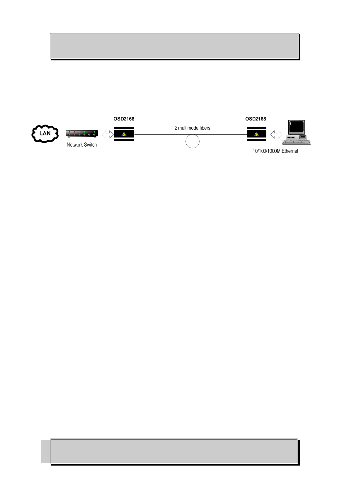
1.2
TYPICAL
CONFIGURATION................................................................................................ 5
1.3
TECHNICAL
SPECIFICATIONS ........................................................................................... 6
1.4
OSD2168M
FRONT
AND
REAR
PANELS ............................................................................ 7
2
INSTALLATION AND OPERATION..................................................................................... 8
2.1
INTRODUCTION .................................................................................................................... 8
2.2
INSTALLATION ..................................................................................................................... 8
2.2.1
WARNING AND PRECAUTIONS..................................................................................... 8
2.2.2
OSD2168M DRAWINGS AND DIMENSIONS ................................................................. 9
2.2.3
POWER SUPPLY CONNECTIONS ................................................................................... 9
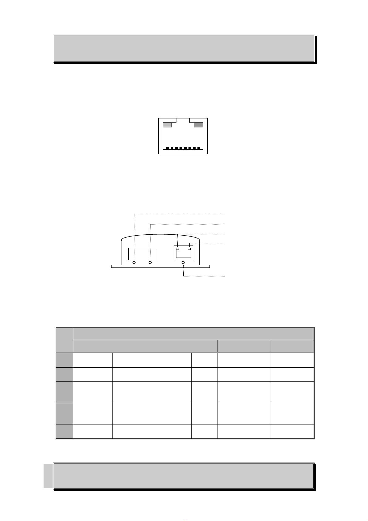
2.2.4
FIXED RJ45 COPPER PORT PIN ASSIGNMENTS........................................................ 10
2.2.5
LED INDICATORS ........................................................................................................... 10
2.2.6
BASIC CONNECTIONS ................................................................................................... 11
3
MAINTENANCE...................................................................................................................... 12
3.1
INTRODUCTION .................................................................................................................. 12
3.2
EXTERNAL
INSPECTION ................................................................................................... 12
3.3
ROUTINE
MAINTENANCE................................................................................................. 12
4
WARRANTY ............................................................................................................................ 13
4.1
WARRANTY
PERIOD.......................................................................................................... 13
4.2
REPAIRS................................................................................................................................ 13
4.2.1
WARRANTY REPAIRS.................................................................................................... 13
4.2.2
OUT-OF-WARRANTY REPAIRS.................................................................................... 13
4.2.3
SITE REPAIRS .................................................................................................................. 13
4.2.4
EXCLUSIONS ................................................................................................................... 13
FIGURE 1: OSD2168M TYPICAL CONFIGURATION........................................................................ 5
FIGURE 2: OSD2168M CONNECTORS................................................................................................ 7
FIGURE 3: OSD2168M MOUNTING DIMENSIONS........................................................................... 9
FIGURE 4: 2168M POWER SUPPLY CONNECTIONS ....................................................................... 9
FIGURE 5: FIXED RJ45 ETHERNET CONNECTOR......................................................................... 10
FIGURE 6: LED INDICATORS............................................................................................................ 10
FIGURE 7: BASIC CONNECTIONS.................................................................................................... 11
TABLE 1: TECHNICAL SPECIFICATIONS ......................................................................................... 6
TABLE 2: DC POWER CONNECTION................................................................................................. 9
TABLE 3: LED FUNCTION ................................................................................................................. 10

OPTICAL SYSTEMS DESIGN
DOC ID: 10114302
OSD2168M OPERATOR MANUAL
PAGE 4
1TECHNICAL SUMMARY
1.1 BRIEF DESCRIPTION
1.1.1 OVERVIEW
The OSD2168M is designed to convert between 10/100/1000Base-T copper cabling and 1000Base-Sx
fiber cabling. It has one PoE+ RJ45 copper port which provides up to 25.4W and one optical port for
operation over two fibers. Jumbo frames are also supported by the OSD2168M.
The unit operates on 850nm wavelength over multimode fiber. Operation over at least 550m of OM or
OM3 multimode fiber limited by the fiber bandwidth.
A major benefit of the OSD2168M is its reliable operation over the -10°C to +55°C temperature range
which allows it to be used in all commercial and many industrial environments.
1.1.2 APPLICATIONS
▲
Any network utilising a mix of copper
and fiber
▲
Secure, noise immune extensions of
gigabit Ethernet backbone networks
▲
Commercial IP communications
▲
Networks with PoE+ devices such as
cameras, WiFi hotspots, etc
1.1.3 FEATURES AND BENEFITS
▲
Complies with
IEEE802.3i/802.3u/802.3ab
10/100/1000Base-T, IEEE802.3z
1000Base-Sx standards.
▲
Supports network traffic of up to
1000Mbps.
▲
Has one fixed 10/100/1000BaseT
copper port and one fixed
1000BaseSx optical port
▲
Automatic MDIX: no need for
crossover cables.
▲
Complies with the IEEE802.3az
Energy-Efficient Ethernet standard
▲
Provides up to 25.4W PoE
▲
Complies with the IEEE802.3af and
IEEE802.3at standards
▲
Supports jumbo frames of up to 10KB
▲
Multimode fiber operation
▲
Available for operation over 2 fibers
▲
Powered by a 50 to 56V
DC
power
supply
▲
Operates over the temperature range
of -10 to +55°C

OPTICAL SYSTEMS DESIGN
DOC ID: 10114302
OSD2168M OPERATOR MANUAL
PAGE 5
1.2 TYPICAL CONFIGURATION
Figure 1 below indicates a typical set-up for an OSD2168M system.
FIGURE 1: OSD2168M TYPICAL CONFIGURATION

OPTICAL SYSTEMS DESIGN
DOC ID: 10114302
OSD2168M OPERATOR MANUAL
PAGE 6
1.3 TECHNICAL SPECIFICATIONS
TABLE 1: TECHNICAL SPECIFICATIONS
SPECIFICATION PERFORMANCE
Electrical Data Interface IEEE802.3i/802.3u/802.3ab 10/100/1000Base-T Ethernet
Electrical Data Rate 10, 100, 1000Mbps with energy detect, auto negotiate, auto MDIX
Optical Data Interface IEEE802.3z 1000Base-Sx
Optical Data Rate 1000Mbps
Operating Mode
Half or full duplex for 10/100
Full duplex for 1000
Pause frames for 1000Mbps flow control
Copper Data Connector RJ45
Power Over Ethernet Up to 25.4W per IEEE802.3at
PoE Pin Assignment 4/5 (+) and 7/8 (-)
Optical Connectors SC
Large Frame Support 10KB
Transmitter Wavelength 850nm
Transmitter Optical Power -9 to -3dBm into 50/125um multimode fiber (OM2, OM3, OM4)
-6 to 0dBm into 62.5/125um multimode fiber (OM1)
Receiver Sensitivity <-17dBm
Receiver Saturation >0dBm
Multimode Fiber Link Budget >8dB: >550m on OM2 or OM3 multimode limited by fiber bandwidth
Dimensions (mm) 60W x 94D x 26H
Weight 0.3kg (module)
Power Requirements -50 to -56V
DC
@ 4W plus up to an extra 33W for PoE operation (attached
powered device dependant)
Power Connector Male jack suitable for standard 2.1mm/5.5mm power plugs such as Switchcraft
S761K or equivalent
Operating Temperature -10°C to +55°C
Relative Humidity 0 to 95% non-condensing
Mean Time Between Failures >400,000 hours at 25°C, Ground Benign Environment per MIL-HDBK-217F
1022216801

OPTICAL SYSTEMS DESIGN
DOC ID: 10114302
OSD2168M OPERATOR MANUAL
PAGE 7
1.4 OSD2168M FRONT AND REAR PANELS
There is one fixed copper port for 10/100/1000Base-T and one SC 1000Base-Sx optical port on the
front panel. The rear panel consists of a 2-way terminal block power connector. Each section will be
described further throughout this manual.
Front Panel
Rear Panel
FIGURE 2: OSD2168M CONNECTORS
Optical Fiber Port
RJ45 Copper Port
Power Connector

OPTICAL SYSTEMS DESIGN
DOC ID: 10114302
OSD2168M OPERATOR MANUAL
PAGE 8
2INSTALLATION AND OPERATION
2.1 INTRODUCTION
This section outlines the methods required to install and operate the OSD2168M successfully. It should
be studied carefully if damage to the equipment or poor results are to be avoided.
This equipment has been fully tested prior to dispatch and is ready for immediate operation. However it
is advisable to check for external transportation damage before operation. If damage is evident, return
the unit with the packaging to your supplier immediately.
2.2 INSTALLATION
2.2.1 WARNING AND PRECAUTIONS
▲
ELECTROMAGNETIC COMPATIBILITY
WARNING: This is a Class A product. In a domestic environment this product may cause radio
interference in which case the user may be required to take adequate measures.
▲
OPTICAL OUTPUT OPERATION
WARNING: Laser Safety: Class 1 Laser Product per IEC/EN 60825-1:2014 standard.
Class 1
The OSD2168M is a Class 1 laser product.
PRECAUTIONS
▲
All service personnel should be provided training as to the hazards of direct viewing of laser
radiation and of the precautionary measures during servicing of equipment
▲
Areas where laser products are installed should be restricted in access to trained service
personnel only and appropriate warning signs posted in the work area.
▲
All laser apertures should be covered by protective covers when not connected to optical
fibers. Never leave outputs uncovered.
▲
Laser equipment should be positioned above or below eye level where possible. Apertures
should be positioned away from personnel.
▲
Protective eyewear should be worn in the vicinity of laser equipment.

OPTICAL SYSTEMS DESIGN
DOC ID: 10114302
OSD2168M OPERATOR MANUAL
PAGE 9
2.2.2 OSD2168M DRAWINGS AND DIMENSIONS
The OSD2168M is designed to be mounted on an even surface and to be secured by means of M4 or
smaller screws.
FIGURE 3: OSD2168M MOUNTING DIMENSIONS
2.2.3 POWER SUPPLY CONNECTIONS
The OSD2168M module requires isolated external DC power. The voltage range of the OSD2168M is -
50V
DC
to -56V
DC
. Power should be connected to the power socket located at the back of the case as
indicated in Table 2.
TABLE 2: DC POWER CONNECTION
Power Connection Specification
Internal Pin 8V
DC
to 35V
DC
External Ground – 0V
FIGURE 4: 2168M POWER SUPPLY CONNECTIONS
R2.1
R2.1
Ø8.5
8.0
8.0
DETAIL A
26.4
60
83.4
DETAIL A
6
94
38
25.6
25.6
+ve

OPTICAL SYSTEMS DESIGN
DOC ID: 10114302
OSD2168M OPERATOR MANUAL
PAGE 10
2.2.4 FIXED RJ45 COPPER PORT PIN ASSIGNMENTS
Figure 5 shows the pin configuration for the fixed RJ45 copper port.
FIGURE 5: FIXED RJ45 ETHERNET CONNECTOR
2.2.5 LED INDICATORS
FIGURE 6: LED INDICATORS
TABLE 3: LED FUNCTION
No
Function
On Off Blinking
Fiber
Link/Act Fiber Link Established Green No Fiber Link Activity
(1)
Power Power On Green Power Off -
Copper
Speed/Status
Copper Link
Green/Amber: 10/100Mbps
Green: 1Gbps
Green/
Amber No Copper Link -
Copper
Link/Act Copper Link Established
Green
or
Amber
No Copper Link Activity
(1)
PoE PD
(2)
detected Green No PD
(2)
detected -
Notes: (1) Activity indicates traffic for both copper and fiber port.
(2) PD: Powered Device
1: Tx+
2: Tx-
3: Rx+
4: PoE (+)
5: PoE (+)
6: Rx-
7: PoE (-)
8: PoE (-)
Amber LED:
Link/Act
Green LED:
Speed/Status
8 7 6 5 4 3 2 1
Fixed Copper Port

OPTICAL SYSTEMS DESIGN
DOC ID: 10114302
OSD2168M OPERATOR MANUAL
PAGE 11
2.2.6 BASIC CONNECTIONS
Figure 7 shows basic user connections to the OSD2168M
FIGURE 7: BASIC CONNECTIONS
OSD2168M
Duplex SC
Fiber cable
RJ45 Ethernet Cable
Power

OPTICAL SYSTEMS DESIGN
DOC ID: 10114302
OSD2168M OPERATOR MANUAL
PAGE 12
3MAINTENANCE
3.1 INTRODUCTION
The following section outlines the fault-finding procedure for the OSD2168M modems. Please take
note of the following:
▲
Personnel without appropriate training should not attempt any maintenance except that outlined
below.
▲
If further maintenance is attempted you are warned that every care should be taken to ensure that
internal measurements made while the equipment is operational are taken carefully as some
components within the unit are expensive and may be damaged by failure of any portion of their
support circuitry.
▲
Some components within the unit are Electrostatic (ES) sensitive and Electrostatic Discharge
(ESD) precautions should be taken when performing maintenance upon the unit.
3.2 EXTERNAL INSPECTION
Visually check for the following:
▲
Check that the correct power source is connected to the power socket.
▲
Check that the Ethernet cables are connected to the modem correctly and that the distant
OSD2168M modem has been connected correctly to any external equipment.
▲
Inspect the optical connectors (for fiber SFP option) for any contamination and clean using
isopropyl alcohol and a lint free tissue if any contamination is detected.
3.3 ROUTINE MAINTENANCE
▲
There is no routine maintenance required with the OSD2168M.

OPTICAL SYSTEMS DESIGN
DOC ID: 10114302
OSD2168M OPERATOR MANUAL
PAGE 13
4WARRANTY
Thank you for purchasing equipment designed, manufactured and serviced by Optical Systems Design
(OSD). OSD warrants that at the time of shipment, its products are free from defects in material and
workmanship and conforms to specifications. Our Warranty conditions are outlined below:
4.1 WARRANTY PERIOD
For warranty period, please call your local OSD distributor.
4.2 REPAIRS
Optical Systems Design reserves the right to repair or replace faulty modules/units. Please obtain a
“Return Material Authorisation” (RMA) form and number before returning goods.
Goods must be returned in adequate packing material to Optical Systems Design, Warriewood or its
nominated authorised representative, for all repairs.
4.2.1 WARRANTY REPAIRS
Return shipments to OSD shall be at customer's expense and freight back to the customer will be at
OSD expense.
4.2.2 OUT-OF-WARRANTY REPAIRS
OSD reserves the right to repair or replace any faulty goods. Freight costs and insurance for both
journeys are met by the user. All equipment repaired by OSD will have a 3-Month Warranty from the
date of dispatch.
4.2.3 SITE REPAIRS
By agreement site repairs may be undertaken for which out of pocket, hotel and travel expenses will be
charged.
4.2.4 EXCLUSIONS
This warranty does not apply to defects caused by unauthorized modifications, misuse, abuse or
transport damage to the equipment. All modifications to OSD’s standard product will need written
authorization and will be charged at normal repair rates. All modifications are to be carried out by OSD
Technicians. Warranty is void if unauthorized removal and/or tampering with serial number and/or
repair labels is evident.

OPTICAL SYSTEMS DESIGN
DOC ID: 10114302
OSD2168M OPERATOR MANUAL
PAGE 14


Optical Systems Design Pty. Ltd.
7/1 Vuko Pl. Warriewood 2102
P.O. Box 891 Mona Vale
N.S.W. Australia 2103
Telephone: +61 2 9913 8540
Facsimile: +61 2 9913 8735
Email: sales@osd.com.au
Web Site: www.osd.com.au
OPTIC L
SYSTEMS
DESIGN
PTY LTD A.B.N. 83 003 020 504
Printed in Australia
Table of contents
Other Optical Systems Design Media Converter manuals

Optical Systems Design
Optical Systems Design OSD2153P User manual

Optical Systems Design
Optical Systems Design OSD2155 User manual

Optical Systems Design
Optical Systems Design OSD2153 Series User manual

Optical Systems Design
Optical Systems Design OSD2167M Series User manual

Optical Systems Design
Optical Systems Design OSD2010 User manual

Optical Systems Design
Optical Systems Design OSD2139 Series User manual

Optical Systems Design
Optical Systems Design OSD2166M Series User manual