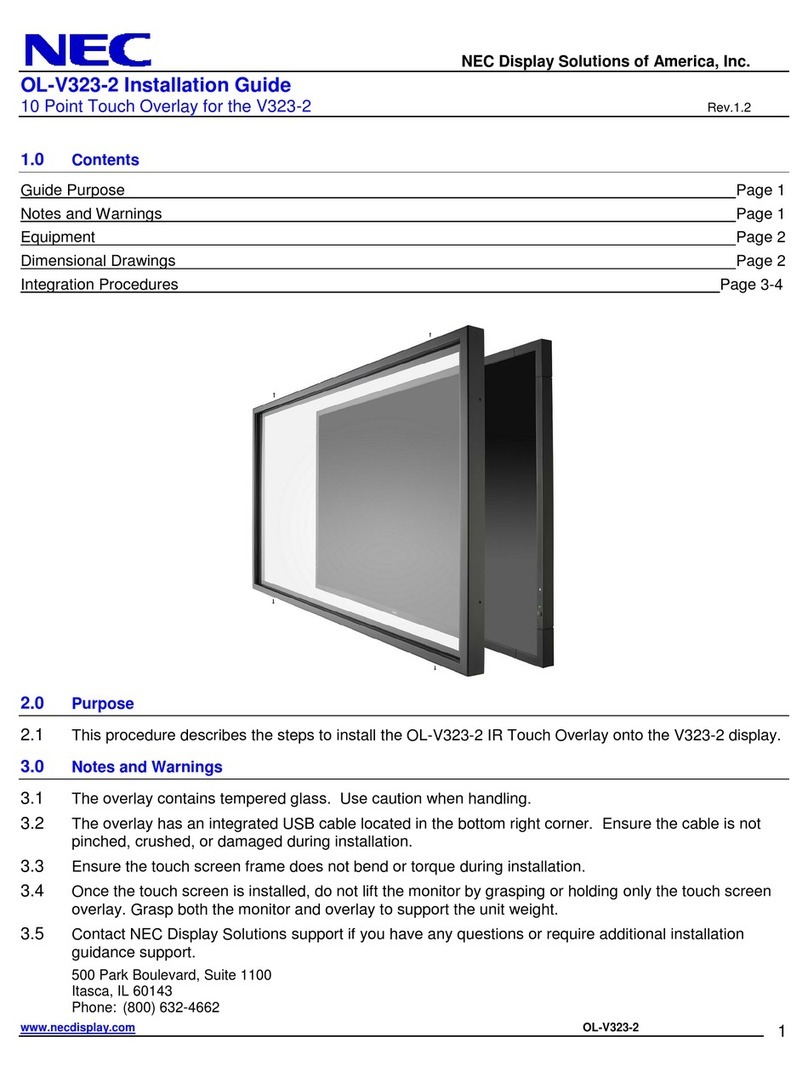
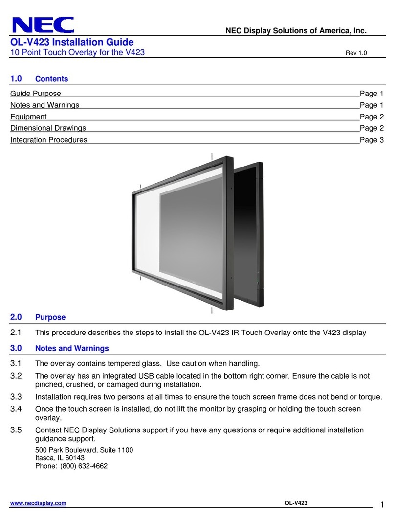
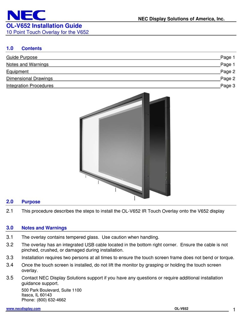
NEC 424 User manual

NP01TM
Installation Manual English
Deutsch
Français
Italiano
Español
Português
Русский
Türkçe
Polski
한글
日本語
Touch Module


Touch Module
NP01TM
Installation Manual
CONTENTS
Introduction .......................................................................................................... 2
Disposing of your used product...................................................................... 2
Read This Before Starting............................................................................... 4
Location to Mount the Touch Module and Mounting Procedure ..... 6
1. Packaged Items............................................................................................. 7
2. Parts Names.................................................................................................... 7
Front face........................................................................................................... 7
Cover Inside....................................................................................................... 8
Rear Face .......................................................................................................... 8
3. Setup Procedure............................................................................................ 9
4. Download the Software Program............................................................ 9
5. Mount the Touch Module at the Top of the Screen........................ 10
6. Connecting the USB Cable ..................................................................... 12
7. How to Use the Antireflection Sheet.................................................... 13
8. Specifications ............................................................................................... 14

ENG-2
Introduction
Thank you for purchasing the NEC Touch Module, NP01TM, hereinafter called the touch mod-
ule or this product in this manual.
By connecting this product to an NEC projector in combined use with an interactive white
board kit, it enables to draw on a screen by fingers instead of using a stylus pen.
Finger touch operation can not be carried on only by this product in independent use.
Make sure to use this product in combined use with the interactive whiteboard kit (camera unit).
Supported interactive whiteboard kit (as of Feb. 2015)
NP03Wi
Supported projectors (as of Feb. 2015)
NP-M352WS, NP-M302WS, NP-M332XS,
NP-UM351W, NP-UM301W, NP-UM361X, NP-UM301X,
NP-UM280X, NP-UM330X, NP-UM280W, NP-UM330W
Disposing of your used product
EU-wide legislation as implemented in each Member State requires that used electrical and
electronic products carrying the mark (left) must be disposed of separately from normal
household waste. When you dispose of such products, please follow the guidance of your
local authority and/or ask the shop where you purchased the product.
After collecting the used products, they are reused and recycled in a proper way. This effort
will help us reduce the wastes as well as the negative impact such as mercury contained in
parts to the human health and the environment at the minimum level.
The mark on the electrical and electronic products only applies to the current European
Union Member States.
Products and company names mentioned in this installation manual may be the trademarks or regis-
tered trademarks of their respective holders.
Note:
(1) Unauthorized reprinting of the contents of this manual is prohibited.
(2) The contents of this manual are subject to change in the future without notice.
(3) The contents of this manual have been prepared with scrupulous care, but please notify
NEC should you have any doubts or notice any mistakes or omissions.
(4) Please note that NEC will accept no responsibility whatsoever for claims for damages, lost
earnings, etc., arising from the use of this product, regardless of article (3) above.
(5) NEC will replace any manuals presenting incorrect collation or missing pages.

ENG-3
DOC Compliance Notice (for Canada only)
This Class B digital apparatus complies with Canadian ICES-003.
RF Interference (for USA only)
WARNING
The Federal Communications Commission does not allow any modifications or changes to the
unit EXCEPT those specified by NEC Display Solutions of America, Inc. in this manual. Failure
to comply with this government regulation could void your right to operate this equipment. This
equipment has been tested and found to comply with the limits for a Class B digital device,
pursuant to Part 15 of the FCC Rules. These limits are designed to provide reasonable protection
against harmful interference in a residential installation. This equipment generates, uses, and can
radiate radio frequency energy and, if not installed and used in accordance with the instructions,
may cause harmful interference to radio communications. However, there is no guarantee that
interference will not occur in a particular installation.
If this equipment does cause harmful interference to radio or television reception, which can be
determined by turning the equipment off and on, the user is encouraged to try to correct the
interference by one or more of the following measures:
• Reorientorrelocatethereceivingantenna.
• Increasetheseparationbetweentheequipmentandreceiver.
• Connectthe equipmentintoan outletona circuitdifferentfromthat towhichthe receiveris
connected.
• Consultthedealeroranexperiencedradio/TVtechnicianforhelp.
WARNING TO CALIFORNIA RESIDENTS:
Handlingthecablessuppliedwith thisproductwillexposeyoutolead, achemicalknown to
the State of California to cause birth defects or other reproductive harm. WASH HANDS AFTER
HANDLING.
DECLARATION OF CONFORMITY
This device complies with Part 15 of FCC Rules. Operation is subject to the following two
conditions. (1) This device may not cause harmful interference, and (2) this device must accept
any interference received, including interference that may cause undesired operation.
U.S.Responsible Party: NEC Display Solutions of America, Inc.
Address: 500 Park Boulevard, Suite 1100
Itasca, Illinois 60143-1248
Tel. No.: (630) 467-3000
Type of Product: Touch Module
Equipment Classification: Class B Peripheral
Model No.: NP01TM
We hereby declare that the equipment specified above conforms to the technical
standards as specified in the FCC Rules.
ENG-4
Read This Before Starting
About the pictograms
To ensure safe and proper use of the product, this installation manual uses a number of picto-
grams to prevent injury to you and others as well as damage to property.
The pictograms and their meanings are described below. Be sure to understand them thor-
oughly before reading this manual.
WARNING Failing to heed this pictogram and handling the product errone-
ously could result in accidents leading to death or major injury.
CAUTION Failing to heed this pictogram and handling the product errone-
ously could result in personal injury or damage to surrounding
property.
Examples of pictograms
The symbol indicates instructions urging caution (including warnings). A con-
crete indication of the caution is given within the symbol.
The symbol indicates prohibited actions. A concrete indication of the prohib-
ited action is given within the symbol.
The symbol indicates required actions. A concrete indication of the required
action is given within the symbol.
WARNING
Laser Safety Caution
• Laserdiodeissealedinthisproduct.Useofcontrolsoradjustmentsofproce-
dures other than those specified herein may result in hazardous radiation expo-
sure.
• ThisproductisclassifiedasClass1ofIEC60825-1:2007.
• ThecautionandexplanatorylabelsoftheCLASS1LASERPRODUCTSisonthe
side face of this product body.
24L79751

ENG-5
WARNING
• Donotlookintothelaserdiffusionpartwhilethetouchmoduleison.Serious
damage to your eyes could result.
• Thefollowingcautionpictogramisindicatednearthelaserdiffusionpart.
• Keepanyopticalitems(aloupe,areflectingmirror,etc.)outoftheprojection
screen area. Visual impairment could result.
• Donotremoveanyscrewsbesidesthespecifiedscrewsinthisinstallation
manual for mounting /demounting this product.
• Donotdisassembleandremodel.Donotsubjectthisproducttoshockorex-
cessive forces. It may cause of fire, shock and laser light leakage.
Contact your dealer for the inspection, adjustment and repair.
• Donotplacethisproductindampplace.Avoiddrippingorsplashingwater
near this product. If water has been spilled into this product, contact your
dealer.
• Donotinsertanymetalorflammableobjects.Itmaycauseoffireandshock.
Pay enough attention to children. If something should fall into this product,
disconnect the USB cable connecting with the projector and contact your
dealer.
• ThepowerforthisproductissuppliedfromtheUSBportonthesupported
projector via the USB cable supplied with this product.
Wrong connection may cause of fire and shock.
CAUTION
• Ifthetouchmoduleismountedwiththebuilt-inmagnets,takeappropriate
countermeasure from falling down. If not, the touch module may fall down and
may cause of injury.
Take security measure by an item supports the MicroSaver® security system.

ENG-6
Location to Mount the Touch Module and Mounting Procedure
• Thetouchmoduleisnotusedoutdoorandintheareadirectsunlightorstronglightstrikes
the screen surface. Operation in bright circumstance as beside a window, near a fi lament
lamp, or a halogen lamp issues much infrared light may cause of malfunction.
• Mountthetouchmodule onto ascreenofwhichsurfacedeflectioniswithin8mm.For
smooth operations, recommend to use a screen which surface defl ection is within 3mm.
• Thetouchmoduleusablescreensizeisfrom60”to100”.
• Forusingthetouchmodule,installtheprojectorbyawallmountunit,aceilingmountunit,
or a table mount unit. If the projector installed on a desktop, the touch module cannot be
used.
• Mountthetouchmoduleatthepositionasthebelowillustrationconsideringtheimagepro-
jection area.
Touch module
Over 100 mm / 4 inches
Screen
Projection area
Over 25 mm / 1 inch
Over 25 mm / 1 inch
Over 25 mm / 1 inch
25mm - 100mm*
/ 1 - 4 inches
* Pay attention to mount not to cut into the projection light.
• Forsecuringthetouchmodule,usethebuilt-inmagnetorcommerciallyavailablescrews.
• Forusingcommerciallyavailablescrews,preparetwo(2)boltsofwhichnominaldiameteris
3mm. Choose an appropriate bolt to your circumstances.

ENG-7
1. Packaged Items
Makesureyourboxcontainseverythinglisted.Ifanypiecesaremissing,contactyourdealer.
Touch Module
Mount at the top of a screen or a white board projected an image
by a projector.
USB cable (3.0 m / 118 inches) x 1 (*For power supply)7N520086
For connecting the USB port on the touch module (type B) and the
USB port on a projector (type A)
Antireflection sheet (Length 175 mm / 7 inches, 12 pcs)
For hiding bumps and obstructions around the screen that dis-
ables to draw utilizing the touch module.
Installation manual (this document)
2. Parts Names
Front face
Dial Cover
USB Port (type B) (*For power supply)
Power Indicator
Security Slot
Centering line

ENG-8
Cover Inside
Adjustment Dial A Adjustment Dial B
CAUTION
• Whenthetouchmoduleismountedonascreenorawhiteboardbymagnets,holdthe
touch module and then remove the cover. Otherwise, the touch module may fall down and
may cause of injury.
Rear Face
Laser diffusion port
Magnet
Caution:
•Donottouchthelaserdiffusionports.Itmaycauseofmalfunction.
Note:
The security slot supports the MicroSaver® Security system.

ENG-9
3. Setup Procedure
STEP 1 Download and install the software program onto the computer.
STEP 2 Connect the interactive whiteboard kit to the projector for enable to use the stylus
pen.
STEP 3 Perform the calibration of the camera.
STEP 4 Mount the touch module at the top of the screen.
STEP 5 Connect the USB cable.
STEP 6 Perform the touch module adjustment.
Note:
• ConcerningtodetailsoftheSTEP1(Howtoinstallthesoftwareprogram),theSTEP3(How
to calibrate the camera), and the STEP6 (How to adjust the touch module), refer to the
software manual that is available from our company website.
4. Download the Software Program
Perform the calibration of the camera unit for the interactive whiteboard kit and adjustment of
the touch module for using the touch module.
The exclusive software program is available from our company website. Please visit our sup-
port site also about operational conditions as supported OS:
URL: http://www.nec-display.com/dl/en/index.html
PDF (Portable Document Format) explains the operations of camera calibration by the software
program and adjustment of the touch module is available. To view or print the PDF files Adobe
ReaderTM is required.

ENG-10
5. Mount the Touch Module at the Top of the Screen
• Built-inmagnetsareloadedontherearfaceofthetouchmoduleasthefactorydefault
setting. No need to secure the touch module by screws on a screen or a white board that
attracts magnets.
• Forusingthetouchmoduleonascreenorawhiteboardthatdoesnotattractmagnets,
remove the built-in magnet from the rear face of the touch module and secure the touch
module with commercially available screws.
• Usecommerciallyavailablescrews(2pcs)innominaldiameter3mm.Prepareboltsthat
are appropriate for your circumstances.
• Projecttheadjustmentscreeninthesoftwareprogram.Thecenterpositionadjustmentline
would be displayed, Align this with the centering line on the touch module.
• Refertopage 5aboutthetouchmodulemounting proceduresbythetableprojection
mount unit.
Note:
• DonotconnecttheUSBcablebeforemountingthetouchmoduleontothescreen.
[1] Decide the position to mount the touch module referring the below picture.
Touch module
Over 25 mm / 1 inch
Over 25 mm / 1 inch
25mm - 100mm*
/ 1 - 4 inches
Over 100 mm / 4 inches
Screen
Projection area
Over 25 mm / 1 inch
* Pay attention to mount not to cut into the projection light.
[2] Mount the touch module onto the screen.
Mounting by the built-in magnets
• Puttherearfaceofthetouchmoduleontoascreenorawhiteboardsincethetouchmodule
has built-in magnets on its rear face as the factory default setting.
• Incase,mountingthetouchmodulebythebuilt-inmagnets,takeappropriatecountermeasure
from falling down. Prepare the commercially available Kensington security wire and connect it
to the security slot on the touch module.

ENG-11
Mounting by commercially available screws
IMPORTANT
• Beforemountingthetouchmodulebycommerciallyavailablescrews,makesurethead-
justment of the touch module (hereinafter described) can be performed properly. Please
consider temporally mount until proper performance of adjustment can be checked. Take
preventivemeasurefromfallingdownforthetemporallymount,too.
• Utilizethemagnetsetholesformountingthetouchmodulebyscrews.
Remove the magnets from the touch module by a plus headed Phillips driver. Keep the removed
magnets and screws.
•
Mount the touch module onto a screen or a white board by commercially available screws.
Reference
• Forusingthetableprojectionmountunit,securethetouch
module by a commercially available double sided adhesive
tape sealed on the rear face of the touch module.
Prepare the double sided adhesive tape of which thick-
ness is in the range from 1.2 mm to 1.5 mm.
CAUTION
• Donotuseadoublesidedadhesivetapebesidesformountingthetouchmoduleona
table. It may cause of injury by fallen down touch module.

ENG-12
6. Connecting the USB Cable
Connect the USB port (type B) on the touch module and the USB port (type A) on the projector
by the USB cable supplied with the touch module.
• Makesuretheprojectorandthecomputerareconnectedbythecomputercable.
• MakesurethecameraunitandthecomputerareconnectedbytheUSBcable.(fortheoptional
interactive whiteboard kit)
Note:
• DonotconnecttotheUSBportontheprojectorforawirelessLANunit.
USB cable (for connecting with the touch module)
Projector
Camera unit
Screen or whiteboard
Touch module
USB Cable (for connecting with the interactive
whiteboard kit)
Computer cable
Computer

ENG-13
7. How to Use the Antireflection Sheet
Use the antireflection sheet supplied with the touch module when finger drawing is
disabled caused on reflection issued by an object laying at the bottom of a screen
such as a pen tray, a whiteboard or a screen frame, etc. Stick on the antireflection
sheet to cut the laser beam diffused by the touch module not to hit the reflection
caused object.
Note:
• Donotpeeloffthereflectionsheetonceit’sstuck.Repetitionofstickingonandoffwill
deteriorate the adhesive force of the sheet.

ENG-14
8. Specifications
Model name NP01TM
Laser class Class 1 (IEC60825-1:2007)
Internal laser diode Total laser power: 200 mW (×2 pcs)
Wavelength: 830 nm
Input terminal USB Type B x 1
Power requirement /
Nominal electric current
DC5V / 400 mA
Power consumption 2W
Weight 290 g / 0.64 lbs
External Dimensions 190(W) •74.5(D) •56.8 (H) (unit in mm) / 7.48(W) •2.93(D) •
2.24(H) (unit in inch) (not including protrusion)
Effective range 60 to 100 inches
Operating temperature and
humidity
5° to 40°C (41° to 104°F) 20% to 80% (non-condensing)
Storage temperature and
humidity
-10° to 50°C (14° to 122°F ) 20% to 80% (noncondensing)

Berührungsmodul
NP01TM
Installationsanleitung
INHALT
Einführung............................................................................................................. 2
Entsorgung Ihres Altgeräts.............................................................................. 2
Lesen Sie dies vor dem Beginn .................................................................... 3
Montagestelle des Berührungsmoduls und Montageverfahren........ 5
1. Enthaltene Teile.............................................................................................. 6
2. Teilebezeichnungen ...................................................................................... 6
Vorderseite......................................................................................................... 6
Abdeckung innen.............................................................................................. 7
Rückseite........................................................................................................... 7
3. Ablauf der Einrichtung................................................................................. 8
4. Herunterladen des Softwareprogramms .............................................. 8
5. Montieren Sie das Berührungsmodul oben am Bildschirm........... 9
6.AnschlussdesUSB-Kabels .................................................................... 11
7. Verwendung der Antireflexfolie .............................................................. 12
8. Technische Daten........................................................................................ 13

GER-2
Einführung
VielenDankfürdenKaufdesNEC-BerührungsmodulsNP01TM,indiesemHandbuchnachfol-
gend als das Berührungsmodul oder dieses Produkt bezeichnet.
Wird dieses Produkt an einen NEC-Projektor angeschlossen und zusammen mit einem interakti-
ven Whiteboard-Set verwendet, kann man mit einem Eingabestift statt mit Fingern auf einem Bild-
schirm schreiben.
Es ist nicht möglich, nur dieses Produkt zu verwenden, um die Bedienung mit dem Finger durch-
zuführen.
VerwendenSiediesesProduktnurzusammenmitdeminteraktivenWhiteboard-Set(Kameraein-
heit).
Unterstütztes interaktives Whiteboard-Set (Stand Feb. 2015)
NP03Wi
Unterstützte Projektoren (Stand Feb. 2015)
NP-M352WS, NP-M302WS, NP-M332XS,
NP-UM351W, NP-UM301W, NP-UM361X, NP-UM301X,
NP-UM280X, NP-UM330X, NP-UM280W, NP-UM330W
Entsorgung Ihres Altgeräts
Die EU-weite Gesetzgebung, wie sie in jedem einzelnen Mitgliedstaat gilt, bestimmt, dass
benutzte elektrische und elektronische Geräte mit dieser Markierung (links) getrennt vom
normalen Haushaltsabfall entsorgt werden müssen. Folgen Sie beim Entsorgen eines sol-
chen Gerätes bitte den Anweisungen Ihrer örtlichen Behörde und/oder konsultieren Sie den
Händler, bei dem Sie das Gerät erworben haben.
Nach der Sammlung benutzter Geräte werden diese erneut verwendet und ordnungsge-
mäß recycelt. Das trägt dazu bei, die Abfallmenge zu reduzieren sowie die negativen Aus-
wirkungen, beispielsweise des in den Teilen enthaltenen Quecksilbers, auf die Gesundheit
und die Umwelt möglichst gering zu halten.
Die Markierung auf elektrischen und elektronischen Geräten gilt nur für die gegenwärtigen
Mitgliedstaaten der Europäischen Union.
Die in dieser Installationsanleitung verwendeten Produkte und Firmennamen können Warenzeichen
oder eingetragene Warenzeichen der jeweiligen Inhaber sein.
Hinweis:
(1) Der unerlaubte Nachdruck der Inhalte dieser Bedienungsanleitung ist untersagt.
(2) Der Inhalt dieser Bedienungsanleitung kann zukünftig ohne Vorankündigung geändert wer-
den.
(3) Die Inhalte dieser Bedienungsanleitung wurden mit großer Sorgfalt zusammengestellt, bitte
benachrichtigen Sie jedoch NEC, wenn Sie Zweifel haben oder Fehler oder Auslassungen
bemerken.
(4) Beachten Sie bitte, dass NEC keinerlei Haftung für Ansprüche für Schäden, entgangene Ge-
winne usw. übernimmt, die aus dem Gebrauch dieses Produkts resultieren, ungeachtet des
oben in Artikel (3) Genannten.
(5) NEC ersetzt alle Handbücher mit falschen Textvergleichen oder fehlenden Seiten.

GER-3
Lesen Sie dies vor dem Beginn
Über die Piktogramme
Um einen sicheren und ordnungsgemäßen Betrieb des Produkts zu gewährleisten, werden in die-
sem Handbuch eine Anzahl von Piktogrammen verwendet, um Sie und andere vor Verletzungen
sowie Sachschäden zu schützen.
Diese Piktogramme und deren Bedeutung werden unten beschrieben. Vergewissern Sie sich, dass
Sie sie vollständig verstehen, bevor Sie dieses Handbuch lesen.
WARNUNG Die Nichtbeachtung dieses Piktogramms und eine fehlerhafte
Handhabung des Produkts können zu Unfällen mit Todesfolge oder
schweren Verletzungen führen.
VORSICHT Die Nichtbeachtung dieses Piktogramms und eine fehlerhafte Hand-
habungdesProduktskönnenzueinerKörperverletzungoderzu
Sachschäden an umliegenden Objekten führen.
Beispiele der Piktogramme
Das -Symbol weist darauf hin, dass Vorsicht geboten (einschließlich Warnungen)
ist. Ein konkreter Hinweis auf die Vorsichtsmaßnahme ist in diesem Symbol darge-
stellt.
Das -Symbol kennzeichnet verbotene Handlungen. Ein konkreter Hinweis auf die
verbotene Handlung ist in diesem Symbol dargestellt.
Das -Symbol kennzeichnet erforderliche Handlungen. Ein konkreter Hinweis auf
die erforderliche Handlung ist in diesem Symbol dargestellt.
WARNUNG
Laser-Sicherheitswarnungen
• LaserdiodeistindiesemProduktverschlossen.DieVerwendungvonBedienele-
menten oder die Änderung von Prozeduren in Abweichung von den in diesem
Handbuch beschriebenen könnte zu einer gefährlichen Strahlenbelastung führen.
• DiesesProduktistalseinGerätderKlasse1vonIEC60825-1:2007eingestuft.
• DieWarn-undErklärungsaufkleberCLASS1LASERPRODUCTSbefindensichauf
der Seite dieses Projektorgehäuses.
24L79751

GER-4
WARNUNG
• SehenSienichtindenLaserstreuungsteil,währenddasBerührungsmodulein-
geschaltet ist. Dies könnte schwere Augenschäden zur Folge haben.
• DasfolgendeWarnpiktogrammbefindetsichnahedesLaserstreuungsteils.
• HaltenSiealleoptischenElemente(eineLupe,einReflektorspiegelusw.)vom
Projektionsflächenbereich fern. Dies könnte zu Beeinträchtigungen des Sehver-
mögens führen.
• EntfernenSienurdieindieserInstallationsanleitungangegebenenSchrauben
für die Montage/Demontage dieses Produkts.
• Nichtauseinandernehmenundverändern.SetzenSiediesesProduktkeinen
ErschütterungenoderübermäßigemKraftaufwandaus.DieskannzuBrand,
Schlag und Laserlichtaustritt führen.
Wenden Sie sich für die Inspektion, Einstellung und Reparatur an Ihren Händler.
• StellenSiediesesGerätnichtaneinemfeuchtenOrtauf.VermeidenSieTropf-
oder Spritzwasser in der Nähe dieses Produkts. Wenn Wasser in dieses Produkt
verschüttet wurde, wenden Sie sich an Ihren Händler.
• SteckenSiekeineMetall-oderbrennbarenGegenständehinein.Dieskannzu
einemBrandundSchlagführen.PassenSiegutaufKinderauf.Sollteetwasin
diesesProduktfallen,ziehenSiedasUSB-Kabelab,dasandenProjektorange-
schlossen ist, und wenden Sie sich an Ihren Händler.
• DieStromversorgungfürdiesesProdukterfolgtüberdenUSB-Anschlussam
unterstütztenProjektorüberdasUSB-Kabel,dasdiesemProduktbeiliegt.
Falscher Anschluss kann zu einem Brand und Schlag führen.
VORSICHT
• WirddasBerührungsmodulmitdenintegriertenMagnetenangebracht,ergreifen
Sie entsprechende Gegenmaßnahmen, damit es nicht herunterfällt. Ansonsten
könnte das Berührungsmodul herunterfallen und eine Verletzung verursachen.
Ergreifen Sie Sicherheitsmaßnahmen durch ein Element, das das MicroSaver®-
Sicherheitssystem unterstützt.
Table of contents
Languages:
Other NEC Touch Panel manuals

NEC
NEC OL-V652 User manual

NEC
NEC OL-V323-2 User manual

NEC
NEC OL-V423 User manual

NEC
NEC 3M V Series User manual

NEC
NEC OL-V463 User manual

NEC
NEC ME Series User manual

NEC
NEC MultiSync M751 IGB User manual

NEC
NEC MultiSync E705 SST User manual

NEC
NEC MultiSync ME431 IR-2 User manual

NEC
NEC OL-V552 User manual