MAXA i-HPV5H 0140 User manual

www.maxa.it
i-HPV5H 0140
i-HPV5H 0250
i-HPV5H 0260
i-HPV5H 0270
R32
This manual has been created for informave purpose. The company declines any responsibility for the results of any projecng or any installaon based on the
explanaons and/or on the technical specicaons provided in this manual. It is besides forbidden the reproducon under any form of the texts and of the gures
contained in this manual. This manual is a translaon from the ocial italian language version. For reasons of environmental respect the Company will not provide
the hard copy in the original language which could be directly requested or downloaded from the Company website at any me. In case of any dispute, the original
language manual will be the trusted one. Even paral reproducon PROHIBITED © Copyright - Advanx SpA
Chiller and Inverter Air/Water heat pumps with axial fans
Controller Manual
Model

00 06-2021 A.B. A.B. First emission
Rev Date Compiled Approved Note
Code Serie
MCO01080100001 Chillers and inverter Air/Water heat pumps with axial fans
Controllo per i-HPV5 Chillers and Inverter Air/Water heat pumps with axial fan
2

3
Controllo per i-HPV5 Chillers and Inverter Air/Water heat pumps with axial fan
Contents
1.PURPOSE AND CONTENT OF THE MANUAL .................................................................. 6
.................................................................................... 6
............................................................ 6
2.PERMITTED USED ............................................................................................................ 6
3. ....................................................................................... 6
...................................................................... 7
.............................................................................. 7
........................................................................................................ 7
......................................................................... 7
4..................................................................................... 7
....................................................................................................................... 8
.......................................................................................................................... 8
............................................................................................................................ 8
.......................................................................................................................... 9
............................................................................................... 9
............................................................................................ 9
................................................................................................ 9
................................................................................................... 9
.................................................................................... 10
..................................................................................... 10
.......................................................................... 10
.................................................................................................. 10
............................................................................ 10
................................................................................................... 10
.................................................................................. 10
.............................................................................. 10
5....................................................................................................... 11
6. ..................................................................................... 11
7. ............................................... 12
8.CIRCULATOR................................................................................................................... 12
...................................................................................... 12
.......................................13
TION................................................................................................................................... 13
............................................13
........................................................ 13
................................................................................ 13
.................................................................................................... 14
9. ...................................................................................... 14
.......................................................................... 14
.................................................................................. 14
10.FAN................................................................................................................................ 15
................................................................... 15
.................................................... 15

Controllo per i-HPV5 Chillers and Inverter Air/Water heat pumps with axial fan
4
..................................................... 16
........................................................... 16
13.REMOTE FUNCTION .................................................................................................... 16
................................................................................................................... 16
..................................................................... 16
........................................................................ 16
.......................................................................... 17
..................................................................................................... 17
......................................................................................... 17
......................................................................................... 17
........................................................................................................................... 17
.................................................................................................... 17
..................................................................................................... 18
........................................................................................ 18
........18
............................................................................................. 18
............................................................................................. 19
.......................................................................................... 19
................................19
................................................... 19
..................................19
................................................................................................. 19
...................................................... 20
........................................................................... 21
............................................................................. 21
............................................................................ 21
.............................................................................. 21
.......................................................................................... 21
.............................................................. 24
....................................................................... 24
24.ALARMS........................................................................................................................ 27
............................................................................................ 27
................................................................................. 27
................................................................................................ 27
.................................................... 27
.................................................................... 27
................................................................................... 28
.......................................................................... 28
.................................................................... 28
.......................................................................................... 28
........................................................................................ 28
................................................................................. 28
............................................................................................. 28

5
Controllo per i-HPV5 Chillers and Inverter Air/Water heat pumps with axial fan
................................................................................................ 28
......................................................................... 28
................................................................................................... 29

Controllo per i-HPV5 Chillers and Inverter Air/Water heat pumps with axial fan
6
1. PURPOSE AND CONTENT OF THE MANUAL
-
HOW TO KEEP THE MANUAL
-
GRAPHIC SYMBOLS USED IN THE MANUAL
2. PERMITTED USED
•
•
improper and therefore not allowed.
•
•
non-experted personnel.
•
•
3. GENERAL SAFETY GUIDELINES

7
Controllo per i-HPV5 Chillers and Inverter Air/Water heat pumps with axial fan
IS PROHIBITED:
Unauthorised access to the electrical panel.
To touch the systems if not autorised to do so.
To step on, sit down on and/or place any type of object on the appliance.
To spary or pour water directly on the appliance.
To touch the appliance when barefoot or part of the body are wet or damp.
-
lease the manufacturer from any civil or criminal responsibility.
CAUTION:
set contact the company.
personnel.
-
trical power.
PERSONAL PROTECTIVE EQUIPMENT
Refer to the user-installer manual included with the unit.
WORKERS' HEALTH AND SAFETY
Refer to the user-installer manual included with the unit.
SAFETY SIGNALS
Refer to the user-installer manual included with the unit.
REFRIGERANT SAFETY DATA SHEET
Refer to the user-installer manual included with the unit.
4.

Controllo per i-HPV5 Chillers and Inverter Air/Water heat pumps with axial fan
8
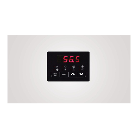
DISPLAY
KEYS
Select the operang mode and manually reset any alarms.
Each me you press the key you have the following sequence:
OFF -> COOL -> COOL+SAN* -> HEAT -> HEAT+SAN* -> OFF (*= if sanitary is enabled)
During parameter seg has the funcon of the back key.
Allows to enter the selected menu to view the sub-folders or to set a value (e.g. summer, winter and domesc set-points or various
parameters).
UP key allows to move to a higher menu or to increase the parameter value.
DOWN key allows to move to a lower menu or to decrease the parameter value.
LED
Cooling mode LED: is on if COOL or COOL+SAN mode is selected.
Heang mode LED: is on if HEAT or HEAT+SAN mode is selected.
Pump LED: is on if the pump is acve.
Alarm LED: is on if there are acve alarms.
Defrosng LED: ashes to enter defrosng mode, it is on when defrosng is in progress.
Compressor LED: ashes if the compressor is starng up, is on if the compressor is acve.
Sanitary LED: ashes if sanitary producon is in progress, it is on COOL+SAN or HEAT+SAN mode is selected and sanitary.
Led KA resistors: is on if the anreeze resistors are acve.

9
Controllo per i-HPV5 Chillers and Inverter Air/Water heat pumps with axial fan
MENU
MENU LABEL LEVEL OTHER CONDITIONS
Setpoint Set User Not accessible if connected at Hi-T2V415
Password PSS User ---
Alarms Err User Only if acve alarms
Probes tP Installer ---
Digital inputs Id Installer ---
Parameters Par Installer ---
Hours of oper-
aon oHr Installer ---
Alarm log Hist Installer Only if the log contains data
Firmware
version Fir Installer ---
USB USb Installer Only with USB key with update les is present
Set
Set DESCRIPTION DEFAULT RANGE UNIT
Coo First summer setpoint 7.0 5 ÷ Coo2 °C
Hea First winter setpoint 45.0 Hea2 ÷ 60 °C
*San Sanitary setpoint 48.0 25 ÷ 60 °C
*San2 Second sanitary setpoin 48.0 25 ÷ 60 °C
Coo2 Second Summer setpoint 18.0 Coo ÷ 25 °C
Hea2 Second Winter setpoint 35.0 25 ÷ Hea °C
Err
tP
tP DESCRIPTION UNIT
t01 Water inlet temperature °C
t02 Water outlet temperature °C
t03 Compressor sucon temperature °C
t04 Compressor discharge temperature 1 °C
t05 Outside air temperature °C
t06 Compressor discharge temperature 2 °C
t08 System remote probe temperature / sanitary (if enabled) °C
t09 Low pressure bar
t10 High pressure bar

Controllo per i-HPV5 Chillers and Inverter Air/Water heat pumps with axial fan
10
Id
Par
Par DESCRIPTION INDEX OF THE PARAMETER
CnF Conguraon H--
ALL Alarms A--
CP Compressor C--
rE Regulaon b--
PUP Pump P--
Fro Electrical resistances r--
dFr Defrosng d--
LbH Minimum Hz L--
rEC Desuperheater rE
oHr
HiSt
Fir
CAUTION: The access to the electrical panel is only allowed to QUALIFIED PERSONNEL.
FIRMWARE UPDATE [UPdF]
PARAMETERS UPDATE [UPPA]

11
Controllo per i-HPV5 Chillers and Inverter Air/Water heat pumps with axial fan
5. SYSTEM RESOURCES
PArCnF.
Resource Parameter
Default
value
ST8 H18 XC-12.1
XC-12.2 0Not set Analogue input congurable with an NTC-10kΏ
probe at 25°C β 3435
ST11 H22 XC-10.1 (GND)
XC-10.2 (+)
XC-11.2 (5V)
0Voltage input 0-10 Vdc input (XC-10.1/2)
Raometric / PWM input
DI2 H46 XC-2.1
XC-2.2 0Remote summer/winter mode
change Voltage free digital input
To acvate the funcon see par. 13.2
DI3 H47 XC-1.1
XC-1.2 2Remote on/o Voltage free digital input. Acve funcon by default
(par. 13.1).
DO7 H85 XP-10.1 (N)
XP-10.2 (fase) 6HDW valve control Voltage output 230Vac, 50Hz, 2A (AC1)
(see paragraph 12)
Modbus
RTU RS485 -- XC-1.1 (GND)
XC-2.1 (R-)
XC-2.2 (R+)
-- -- Factory enabled with CM accessory
6.
-
PArrE
• b08 = 1b08 = 0
• b09
• b10
• b11
• b12
• b13
• b14
HEATING COOLING
Set temp. ext
b12
b10
b14
Delta <0 Delta >0
Temp.
ext
Temp.
set
Offset >0
Hea
Set temp. ext
b11
Temp.
set
Offset <0
Coo
b13
Delta <0 Delta >0
Temp.
ext
SETPOINT DINAMICO - RAFFRESCAMENTO
b09
• set-point of 28°C with external temperature of 18°C
• set-point of 45°C with external temperature of 2°C
•
•

Controllo per i-HPV5 Chillers and Inverter Air/Water heat pumps with axial fan
12
•
• set-point of 12°C with external temperature of 25°C
• set-point of 7°C with external temperature of 35°C
•
•
•
7.
H22 = 40. To use this func-
• b15
• b20 = 0
• b20 = 1
•
•
•
SETPOINT FROM ANALOGUE INPUT
Input 0-10V
Ra�ometric input
Temp.
set
Coo/Hea
Coo/Hea + b15/2
Coo/Hea
-
b15/2
0 V
0 %
5 V
50 %
10 V
100 %
•
•
•
8. CIRCULATOR
PArPUP.
• P03 = 0
• P03 = 1
NOTE:.
CONTINUOUS OPERATION

13
Controllo per i-HPV5 Chillers and Inverter Air/Water heat pumps with axial fan
OPERATION ON CALL BY TEMPERATURE CONTROLLER
P01
P02
OPERATION ON CALL FROM TEMPERATURE CONTROLLER
Temperature controller
ON
OFF
�me
Compressor
�me
Pump
�me
P01
P02
ON
OFF
ON
OFF
OPERATING ON CALL BY TEMPERATURE CONTROLLER WITH PERIODIC ACTIVATION
• P16
• P17
P17 = 0
OPERATION WITH INTEGRATION RESISTOR ACTIVE
If parameter r33 > 0
ANTIFREEZE HYDRAULIC PUMP OPERATION
P04
P04 + P05
PROPORTIONAL REGULATION
• P06
• P07
• P08 = Minimum speed
• P09
• P10
PROPORTIONAL REGULATION
ΔT
[°C]
Speed
[%]
P07
P08
P06/P09
P10

Controllo per i-HPV5 Chillers and Inverter Air/Water heat pumps with axial fan
14
-
SYSTEM VENTING
• Set unit to OFF
•
• Press UP and DOWN
MODE/ESCUP and DOWN
3 seconds.
water inside the system.
9. COMPRESSOR ON/OFF LOGIC
that
REGULATION IN COOLING MODE
• Tw,out,set
•
• b05
• b25
RPM
Tw,out (outlet water temp.)
Tw,out,set
HzMaxReg
OFF
HzMin
b05
∆T,set + b25
• Tw,out < Tw,out,set - b05
• The compressor restart when : if
REGULATION IN HEAT MODE
• Tw,out,set
•
• b05
• b25

15
Controllo per i-HPV5 Chillers and Inverter Air/Water heat pumps with axial fan
RPM
Tw,out (outlet water temp.)
Tw,out,set
HzMaxReg
OFF
HzMin
b05
∆T,set + 2°C
• Tw,out > Tw,out,set + b05.
• The compressor restart when : if
10. FAN
11. COMPRESSOR CRANKCASE RESISTENCE
12. ENABLING DOMESTIC HOT WATER PRODUCTION
= 6.
=
6
H10:
Parameter VALUE
H19 6DHW temperature probe
H85 6DHW valve control
H10
0 (default) Funcon disabled
1Funcon acve in heang and cooling mode.
The remote on/o funcon does not disable DHW producon.
2Funcon acve in heang and cooling mode.
The remote on/o funcon disables DHW producon.
3Funcon acve only in heang mode.
The remote on/o funcon disable DHW producon.
4Funcon acve only in heang mode.
The remote on/o funcon disable DHW producon
5 Funcon acve only in cooling mode.
The remote on/o funcon not disable DHW producon.
6Funcon acve only in cooling mode.
The remote on/o not disable DHW producon
If H10H10 = 2/4/6, the re-

Controllo per i-HPV5 Chillers and Inverter Air/Water heat pumps with axial fan
16
MEMORISING THE PROBE IN HEATING MODE
•
• b06
HEATING MODE ON DHW STORAGE TANK
If parameter H130 = 1
13. REMOTE FUNCTION
ON/OFF
H47 = 2
SUMMER/WINTER MODE CHANGE
H46:
Parameter VALUE
H46
0 (default) Funcon disabled
3Open contact -> cooling mode
Closed contact -> heang mode
DHW CALL DROM DIGITAL INPUT
the contact opens.

17
Controllo per i-HPV5 Chillers and Inverter Air/Water heat pumps with axial fan
SYSTEM WATER REMOTE PROBE
•
•
•
• Coo + b22
14. DEFROSTING CYCLE
15. MINIMUM HZ FUNCTIONS
Parameter VALUE
L02 0Funcon not acve
1Enable Hz minimum
L03
0Funcon not acve
1Funcon acve only in cooling mode
2Funcon acve only in heang mode
3Funcon acve only in sanitary mode
4Funcon acve in cooling and sanitary mode
5Funcon acve in heang and sanitary mode
6Funcon in cooling and heang model
7Funcon always acve
16. MAXIMUM HZ FUNCTIONS
17.
18. SYSTEM RESOURCES
Resource Parameter
Default
value
DI6E H60 XCE 2.1 /2.2 0Not set Voltage free digital input.
DI9E H63 XCE 4.1 /4.2 0Not set Voltage free digital input.
D01E H86 XPE-1.1/1.2 48 Compressor operaon indicaon Voltage output 230Vac, 50Hz, 2A (AC1)
D02E H87 XPE-2.1/2.2 24 Alarm signalling Voltage output 230Vac, 50Hz, 2A (AC1)
D03E H88 XPE-3.1/3.2 21 *Defrost signal in progress Voltage output 230Vac, 50Hz, 2A (AC1)

Controllo per i-HPV5 Chillers and Inverter Air/Water heat pumps with axial fan
18
Resource Parameter
Default
value
D04E H89 XPE-4.1/4.2 31 *Sistem season indicaon Voltage output 230Vac, 50Hz, 2A (AC1)
D05E H90 XPE-5.1/5.2 25 Double setpoint / 3-way valve for
radiant panels Voltage output 230Vac, 50Hz, 2A (AC1)
19.
Parameter VALUE
H60 26 Call for second set-point
H90 25 3-way valve for radiant panels
H129
0Funcon disabled
1Funcon congured but not acve
2Enabled only in cooling mode
3Enabled only in heang mode
4Enabled in cooling and heang mode
SILENCED VENTILATION
Parameter VALUE
H63
0 (default) Funcon disbled
25 Open contact -> standard mode
Close contact -> silenced mode
20.
Parameter VALUE TERMINAL
rE01 1DS enabled in chiller mode
H17 6XC-121.1/12.2 DS water temperature sensor
•
•
•
-
perature exceeds the setpoint San.
-
ress.
21. AUXILIARY RESISTANCES

19
Controllo per i-HPV5 Chillers and Inverter Air/Water heat pumps with axial fan
mode and if r10 = 1.
•
•
•
•
SYSTEM RESISTENCE
Parameter VALUE
H87 22 System integraon resistance
r10 1Enabling of system resistors
r11 5 (default) Delta resistances in system integraon (in tenths of °C)
r12 10 (default) System integraon acvaon delay (in minutes)
r21 1Enabling resistors during defrosng
r24 1/3 Type of use resistors
SANITARY RESISTANCE
Parameter VALUE
H88 26 DHW integraon resistor
r15 1Enabling of DHW resistors
r16 10 (default) Sanitary integraon acvaon delay (in minutes)
r24 2/3 Type of use of resistance
INDIVIDUAL SYSTEM/HEALTH INTEGRATION RESISTENCE
r15 = 2 and r24 = 3.
INTEGRATION RESISTANCE SELECTION MODE
r14 = 0
•
•
•
CIRCULATOR MANAGEMENT WITH ACTIVE RESISTANCE
-
•
•
•
•
BOILER ENABLING
•

Controllo per i-HPV5 Chillers and Inverter Air/Water heat pumps with axial fan
20
•
•
•
•
•
•
•
•
•
•
Parameter VALUE
H88 29 Boiler enabling
r10 1Enabling in system integraon
r12 10 (default) System integraon acvaon delay (in minutes)
r15 1Enabling of sanitary integraon
r16 10 (default) DHW integraon acvaon delay (in minutes)
r23 1 ÷ 6 Type of boiler use
r32 1 ÷ 3 Boiler equipment
LOGIC OF INTEGRATION HEATERS AND/OR BOILER IN JOINT OPERATION OR IN SUB
STITUTION OF THE HEAT PUMP COMPRESSOR
•
•
•
•
•
•
LOGIC OF INTEGRATION
r22
Heat pump + Boiler/Heater
JOINT OPERATION I ZONE
Boiler + Heat pump/Heater
JOINT OPERATION II ZONE
Boiler/Heater
OPERATION IN SUBSTITUTION
Heat pump
STANDARD WORKING
r28
r08
Outside
temp.
This manual suits for next models
3
Table of contents
Other MAXA Inverter manuals