Nedap Invexs M190 Instructions for use
EN
Date: 21-03-2017 Version 8.0 Document no.: 5278210
This information is furnished for guidance, and with no guarantee as to its accuracy or completeness; its publication conveys no license under any patent or other right, nor does
the publisher assume liability for any consequence of its use; specifications and availability of goods mentioned in it are subject to change without notice; it is not to be
reproduced in any way, in whole or in part, without the written consent of the publisher.
© Nedap N.V., P.O. Box 103, NL-7140 AC GROENLO, The Netherlands
1. General
The Invexs 190 reader series is capable of reading (simultaneously) Nedap,
Mifare and DESFire credentials due to its dual reader technology. The
Invexs 190 is designed to be used on door pillars (mullion) and suitable for
outside and inside use. A model with keypad is also available. The Invexs
output can be set to either Wiegand, XS RF modulation or RS485 protocol
(plain or encrypted). Functionality and output are determined by the
configuration of the Invexs reader. The configuration is defined using the
programm AEreco, and deployed by the configuration card or via AEmon.
(More information about configurations can be found in Convexs Invexs
Installation Manual). Three LEDs (red, green, blue) and beeper are included.
LEDs around the keypad ciphers light up only in case a PIN code is
requested. The pigtail cable can be lead directly backwards or when using
the additional spacer (art. nr . 9949887) to the top or bottom.
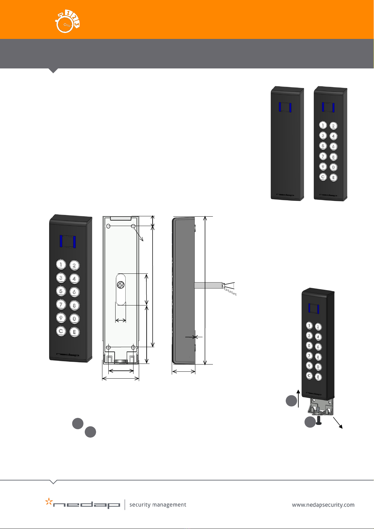
2. Dimensions
3. Mounting Procedure Invexs
For mounting the Invexs 190, the mounting plate must be placed on the wall
first. For removing the mounting plate from the Invexs 190, unscrew the
screw (Torx, M5) at the bottom of the Invexs and push the Invexs 190
slightly up . The plate can be mounted using the 4 holes.Place the cable to
the correct position and replace the Invexs 190.
Invexs 190 Readers Mifare Nedap dual technology mullion readers
Quick Install sheet
EN
Un screw
Push up
2
1
Mounting
plate
1
191
30
10 x 0.14
Shield
32
155
12
40 14.5
50
4 x 5
75
Dimensions: 191 x 50 x 30 mm.
4 mounting holes available at 32 x 155 mm
Cable pigtail: 10 x 0,14 mm shielded, 3m
Optional spacer (max thickness 10 mm) is
available for other cable outlet (top or
bottom)
01
02
01
02
2
EN
Quick Install sheet | Invexs 190 Readers Mifare Nedap dual technology mullion readers
Version 8.0
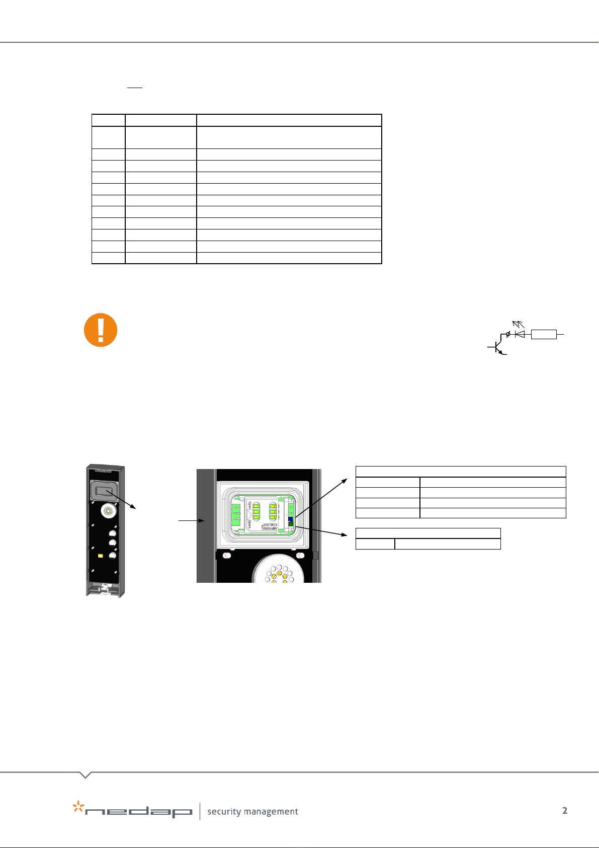
SAM cover
4. Connections
Invexs is not hot-swappable, so when making/changing connections power must be switched
Off.
Wire
Colour
Function
1
Red
Power in (12-30VDC) /
XS modulator (120kHz)
2
Black
Power Ground / RF Ground
3
Grey
RS485 A (-)
4
Violet
RS485 B (+)
5
Green
Wiegand Data 0 (D0)
6
White
Wiegand Data 1 (D1)
7
Yellow
Beep input (BEEP)
8
Pink
UL LED input (UL*)
9
Blue
MD LED input (MD*)
10
Brown
NA LED input (NA*)
11
Shield / Metal
EM shield (connected to power ground)
•Cable shield (wire 11) must be connected to the metal case of the external device
•If connected to a 120kHz RF device (AEOS Nedap reader AEpack or XS device) the
power is supplied via the Convexs adapters (AX1014 for AEpacks, AB350 for XS
devices). Existing antenna cabling can then be reused for connecting the Invexs.
On the AX1014 an additional connection between GND (for UL and NA) and
Antenna GND must be made on the AX1014 (Invexs 190 has no separate cable
for this connection).
•UL*,NA*, MD* and BEEP are inputs for Open Collector to GND. If the Convexs
adapters are used, the original UL and NA signals are converted to the UL* and NA*.
5. LED Indicators Inside / Backside
There are two LEDs available: Blue for Status (of application), Green for Identification (both
visible behind the SAM cover at the back side)
6. LED Indicators Front
At the front a three colour LED is positioned at the middle of the Invexs
Depending on the used configuration the function of these LEDs can differ:
•Green LED:Card is been authorised (UL LED)
•Red LED:Card is not authorised (NA LED), controller is stand-by
•Blue LED:
Blinks fast: No configuration is available at this Invexs (present Configuration
card or load Configuration first).
Continuously ON: Determined by configuration: E.g. Reader stand-by.
(Blue LED is activated if UL is OFF and NA is more than 1 sec OFF)
R
GND
UL*/NA* / BEEP
ID (green)
Blinking
Card detected
ST: STATUS (blue)
Slow blinking
Application running (operating)
Fast blinking
Downloading or error during loading
2 short flashes
Application present but not active
3 short flashes
No application present
3
EN
Quick Install sheet | Invexs 190 Readers Mifare Nedap dual technology mullion readers
Version 8.0
Function of LEDs and Beeper is controlled by used application settings of Invexs.
Green and Red LED can be controlled by hardware signals (wire 8 and 10) or RS485NR,
Blue LED indirectly by UL and NA, if this setting is activated (configuration) or by wire
9. Beeper can be controlled by hardware signal (wire 7), RS485NR or software
(configuration).
7. Firmware
Pay attention that the firmware loaded in the Invexs together with the Invexs type and
configuration determines functionality and protocols. Default (from factory) the Invexs handles
the credentials on several ways simultaneously:
•XS cards as: RS485NR, RF badge
•Mifare cards (CSN) as: RS485NR, RF data
The Invexs 190 requires dedicated firmware (not identical to the Invexs 170 firmware)
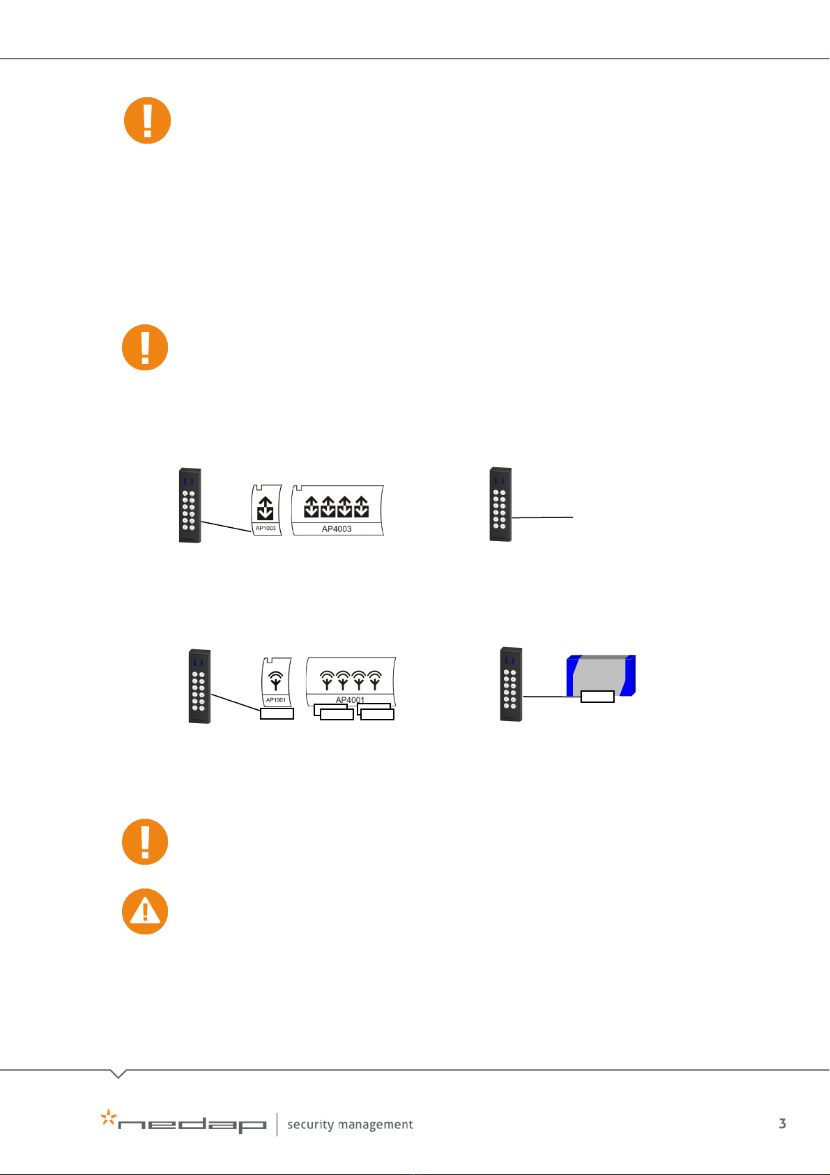
8. System Configurations (how to connect Invexs readers)
Configurations can be determined by the AEreco (loaded by AEmon or configuration
card)
Check the Convexs Invexs Installation Manual chapter 8 (Available reader Firmware) for
the compatibility for the used readers
Invexs uses existing antenna cabling
(Coax + 3*0,25qmm for LEDs).
On each AEpack
-RF interface an AX1014
must be added. Connections: see AX1014
RF interface AEpacks
Accessor III /
SimpleXS
AX1014
AX1014
AX1014
AX1014
AX1014
AB350
RF interface XS systems
Invexs uses existing antenna cabling
(Coax + 3*0,25qmm for LEDs).
On each XS reader
-RF interface an AB350
must be added. Connections: see AB350
To APx003 readers with RS485 special encrypted
protocol.
(LEDs, Beeper, Keys and Display are
controlled over the RS485 communication)
AEOS RS485 interface
- Third party systems
-
AEOS Wiegand
Wiegand interface
Wiegand output connected to Third party systems
(or to AEOS Wiegand interfaces). LEDs andBeeper
are controlled by hard wiring. (PINcode possible)
4
EN
Quick Install sheet | Invexs 190 Readers Mifare Nedap dual technology mullion readers
Version 8.0
9. Tamper Switch
The Invexs 190 is equipped with a tamper switch which can be monitored over the RS485NR
protocol.
10. Beeper Indications
Beeper is also used for indication of loading the configuration:
•High sound beep (‘happy sound’): Configuration is loaded correct, second high sound
beep indicates that this configuration can be used with this Invexs
•Low sound beep (‘unhappy sound’): Configuration is not correct loaded or no
configuration available at start-up
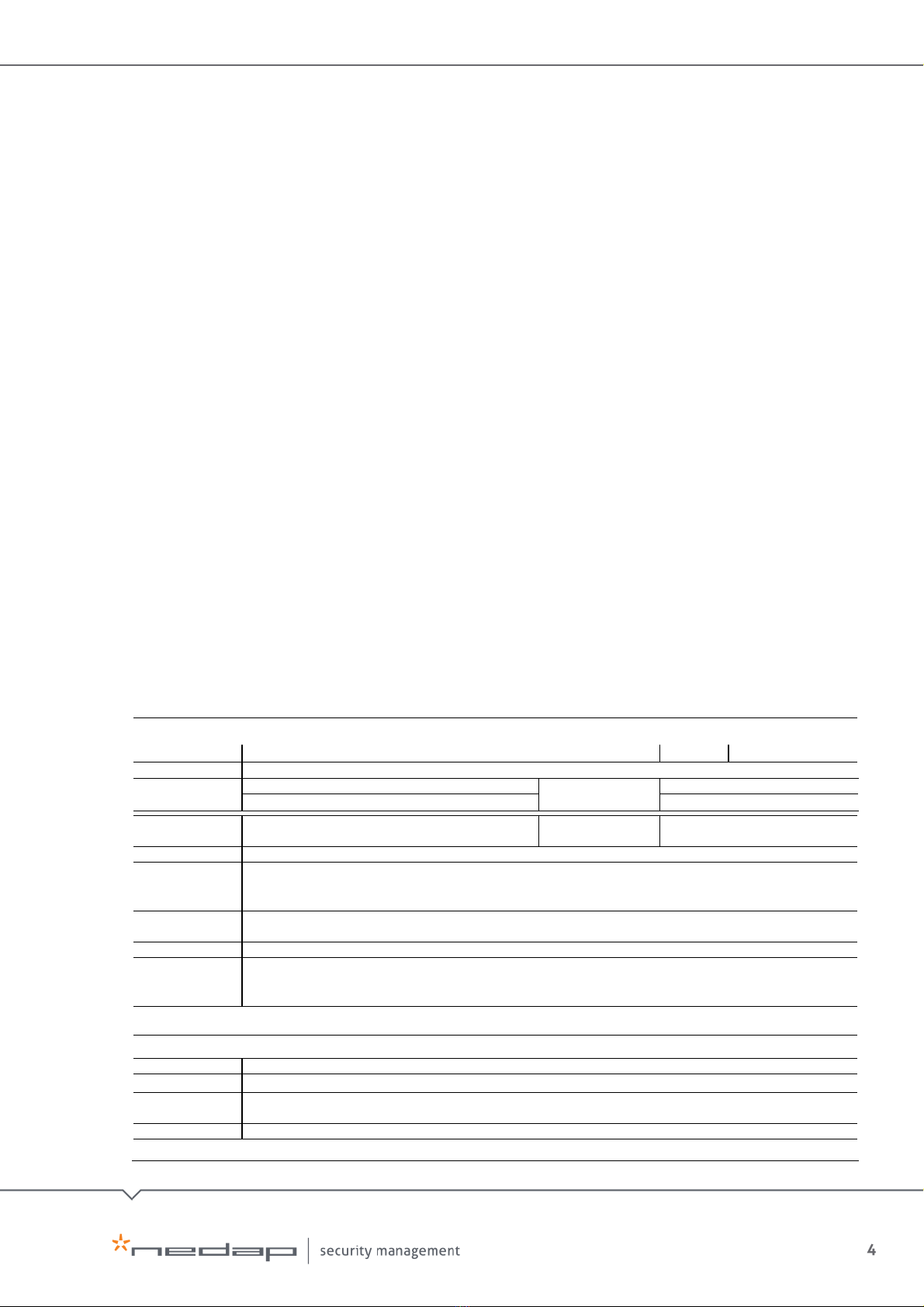
SPECIFICATIONS Invexs 190: MD190 (article no.9948406), MND190 (article no.9948414), MDK190 (article no.9948457),
MNK190 (article no.9948449), MNDK190 (article no.9948465)
Discontinued products: M190 (article no. 9945512), MN190 (article no. 9948392), MK190 (article no. 9948422)
Dimensions:
191 x 50 x 30 mm
Weight:
± 350 gr
Protection:
IP65
Power Supply:
M(N)(D)190 12 – 30VDC, 60 - 24mA SELV
Power
Consumption:
60mA@12VDC, 35mA@24VDC
M(N)(D)K190 12 – 30VDC, 90 - 36mA SELV
90mA@12VDC, 45mA@24VDC
Environment:
Temperature: Operating:-30 – 65°C,
Storage:-30 – 65°C
Relative humidity:
10 – 93% non-condensing
Tamper switch:
Yes
Communication
RS485 (Encrypted AEOS protocol to APx003, (firmware APx003rs485NR). RS485 plain
Wiegand Data 0 and Data 1 (protocol depending on configuration)
RF Modulator (120 kHz for AX1014 or AB350)
Inputs:
Beeper (Beep ON / OFF, controlled by application) and Open collector to GND, max 20mA
UL*, NA*, MD* LED Open collector to GND, max 20mA
Indicators:
UL (green) NA (red) ,MD (blue)
Antennas
(internal):
Antenna 1: 120 kHz, Nedap XS compatible (PM and AM cards). Detection distance UniXS card: 8 cm
Antenna 2: 13,56 MHz, Mifare compatible Detection distance Mifare card: 4 cm
Mifare EV1 card: 2 cm
CABLE SPECIFICATIONS
10 wire shielded cable of approx. 3 meters length included (pig tail). Extensions can be made:
RS485:
2 x 2 x 0,25mm² shielded, max cable length: 1000 meter, cable capacity <= 100pF/meter
UL/GND/NA:
3 x 0,25mm², max cable length: 50 meter
XS MOD / GND:
Coax RG58U, max cable length: 50 meter
Or 5 x 0,25mm² shielded, max cable length: 50 meter, cable capacity <= 100pF/meter
Wiegand:
4 x 0,25mm² shielded (excl. LEDs), max cable length: 150 meter, depending on receiving device
MORE INFORMATION: Contact your local Nedap supplier or check our website www.nedapsecurity.com
This manual suits for next models
16
Other Nedap Security System manuals


