Epicalert Apex EPIC-AP130 User guide

1

2
Table of Contents
1. System Introduction....................................................................................3
1.1. System Setup.........................................................................................4
1.2. Specifications.........................................................................................7
2. Operation....................................................................................................9
2.1. Alarm Activation .....................................................................................9
2.2. Standby Mode......................................................................................11
2.3. Digital Reporting Methods....................................................................15
2.4. Walk and Range Test...........................................................................18
2.5. Global Test...........................................................................................18
2.6. Factory Reset.......................................................................................19
3. Enrolling Devices......................................................................................19
3.1. Zones...................................................................................................19
3.2. Enrolling Methods.................................................................................20
3.3. User Enrolling Pendant 1 .....................................................................21
3.4. User Enrolling Pendant 2 .....................................................................21
3.5. Removing Pendant 1 and 2..................................................................21
4. SystemConfiguration ...............................................................................23
4.1. Entering Programming Mode...............................................................23
4.2. Programming Your Apex......................................................................25
5. Appendix ..................................................................................................46
Appendix A: CID Event code............................................................................46
Appendix B: Apex Programming Overview......................................................49
Appendix C: Apex Programming Worksheet....................................................53
Appendix D: Beep Definitions...........................................................................57
Appendix E: Apex Voice Prompts ....................................................................58
This guide provides the basic installation, programmingand wiring information requiredfor Apex. This
guide should be used in conjunction with the Apex User Manual, which is included in the kit or
available for download from Epic Safety website at: www.epicsafety.com

3
1. System Introduction
Apex is a base unit that acts as the core device in an Epic Alert Personal
Emergency Response system. The system has compatibility with 11 different
devices and a multitude of capabilities that include call cancelling features, non-
emergency phone calls and fully programmable sections.
Compatible Devices:
Oval Nano Pico
Fall Sensor Emergency Pendant Emergency Button
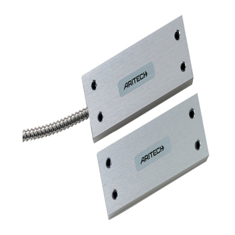
Tact Wave
Door Contact Motion Detector

4
1.1. System Setup
1.1.1. Identifying the Parts
TOP VIEW
REAR VIEW
BACK VIEW

5
1. Blue Help Button (with backlight)
o
Press to call for help
o
Backlight will light up during calls
o
Backlight flashes during the HELP ARRIVED MODE
o
Backlight designed for easy access at night
2. Green Reset Button
o
Press to end a help/phone call during an active call session
o
Press to confirm that help has arrived
o
Press once to check in for inactivity monitoring
o
Press and hold for 16 seconds to disable inactivity monitoring
o
Press and hold for 3 seconds to dial the programmed non-
emergency phone number.
o
Before Apex dials out for alarm reporting, press once to cancel the
alarm reporting.
o
Press once to report that help has arrived when help arrived mode is
active.
o
Press once to cancel alarm reporting
o
Press twice to cancel help arrived mode
3. Red LED Light
o
Solid light - when a call is in progress
4. Green LED Light
o
Solid light - when Apex is ON
o
Flashes every second - when the power cord is unplugged
o
Flashes every two seconds - when the unit or associated devices
have low battery
o
A slow flash - indicates a phone line problem
o
A quick flash every 2 seconds - indicates supervision failure
5. Microphone
6. Speaker
7. Phone Jack (marked)
o
Telephone unit connection
8. Line Jack (marked)
o
Phone line connection from wall
9. DC Jack
o
DC 12V 1Apower adapter
connection

6
10. Battery Switch
11. Temperature Sensor
12. Local Programming Input
o
Use the special telephone cord to connect
Apex and a telephone
unit
for local programming.
13. Mounting Holes
14. Mounting Bracket
1.1.2. Locating a suitable position
•
Apex should be placed in an easily accessible location near a power outlet
and telephone line connection.
•
Do not place Apex near heat sources, such as a microwave, as this can
reduce signal strength and avoid damp locations, such as the bathroom.
•
Do not place Apex alongside other radio transmitting devices, such as
mobile phones, cordless phones, or wireless computer network (Wi-Fi)
devices.
•
Do not place Apex under direct sunlight as this can affect the functionality
of the temperature sensor.
1.1.3. Mounting Apex
Apex can be mounted on the wall or placed flat wherever desired (e.g. on a
table). If mounted on a wall, ensure Apex is fitted near chest height where the
buttons, microphone and speaker can be easily accessed and operated.
1.
Using the Wall Mounting Bracket as a template, mark off two hole
positions on the wall.
2.
Drill two holes. Insert the wall plugs included if the wall is plaster or brick
•Ensure there are no hidden cables or pipes.
3.
Screw on the bracket to the wall.
4.
Hook Apex onto the bracket, with the front facing towards you.

7
1.1.4. Line Seizure
Apex has a line seizure feature and can control the telephone line. When wired
correctly, even if the phone line is previously engaged, Apex can circumvent the
line and place a help call. The line seizure feature is only available when the
household phones are connected to the phone jack via Apex.
Apex has master control over
Phone B but not Phone A
1.2. Specifications
User Features:
Built-in low and high temperature sensor
Voice prompt notifications
Two way voice communication on base unit
Calls up to 4 programmable numbers: choice of 4 account numbers or
one global account number.
Supports call cancel feature on base unit and all compatible devices.
Can call a single non-emergency number.
Answers and terminates incoming phone calls (ringer enabled/disabled).
Control over phone line use (line seizure) even if the phone line is
engaged.
User can program/enroll up to 2 pendants
Detects no pendant present
Low battery alert for base unit and other devices
Telephone fault and power failure notification
Programmer/Installer Features:
Inactivity monitoring for 0 to 24 hours
Help arrived mode can be enabled or disabled
Help arrived monitoring time is programmable up to 15 minutes after
initial help call.

8
oSends additional “help not arrived” signal to Central Monitoring
Station
oFollow up calls to make sure emergency help has arrived
Two way communication sessions can be programmed to last from 1 to
10 minutes (Gives warning beeps and session time can be increased).
Optional delay on signal transmission programmable for up to 99
seconds.
Fall sensor has its own programmable delay time for activity after a fall
Fall sensor transmits an inactivity signal if it does not detect any
movement after the fall.
Locally programmed with any regular telephone set
Does not need special programmer
Remote programming from anywhere through any phone (ring count or
auto-answering enabling for remote programming).
Communication formats: Contact ID, Two Way Voice
Up to 10 devices (including pendants) can be programmed to the base
unit.
Periodic test transmission from Apex can be made every 1 –7 or 30
days (can set to 0 for no test transmissions).
Device supervisory signals can be set every 1 - 30 days
Fault alerts can be set to silent mode or audible mode
Global test feature (to check if the complete system is working properly)
Walk/range test available to determine the operation range
Remove devices individually or as a group
After help signal is sent to monitoring station, CMS has 2 follow on
choices: start two-way communication or listen-in.
Tone or pulse dialing mode
Silent or audible transmitter
Programmable installer’s code
Can program a single device to send silent or audible panic alarm
Half duplex or full duplex voice communication
Base unit AC failure and low battery report
Technical Specifications:
Power: 12V 1A adapter
Backup battery: 7.2V 1300mAh Ni-Mh rechargeable battery x 6
Battery backup time: 32 hours minimum
Speaker: 3W

9
Radio frequency: 433 MHz
Range: Over 200 meters in open space
Operating temperature: -10° to +45°C
Humidity: Up to 90% non-condensing
Dimensions: 200.2 X 149 X 55.5 mm
2. Operation
2.1. Alarm Activation
When an alarm is triggered, the RED LED light and the HELP button backlight
will light up. Apex will call for help according to the programmed reporting method
and guard time delay.
- An alarm report can only be cancelled by pressing the RESET button.
- During the transmission period, all supported devices can cancel alarms
that they have triggered by pressing the EMERGENCY button on the
device for 8 seconds.
- All supported devices can end a voice session they have triggered by
pressing the EMERGENCY button on the device for 8 seconds.
Alarm Call Voice Prompts
When an alarm has been triggered by any device, Apex will indicate the status
of the alarm call with voice prompts. Please see Appendix E: Apex Voice
Prompts for a complete list of the voice prompts.
2.1.1. Help Arrived Confirmation Mode
The Help Arrived Mode (Section 33) option must be turned on for this function.
Help Arrived Mode will activate after the alarm is triggered and all voice sessions
with the call sequence phone numbers have ended. When activated, Apex will
start the Help Arrived Timer set in Section 67 and the HELP button will flash.
One minute after the two way voice communication session ends, the
voice prompt “If help has arrived, press the green RESET button” will play
every minute until the RESET button is pressed (once or twice).

10
oThe RESET button can be pressed twice to send a “Help Arrived
Mode Cancelled” report (code 647) to the CMS. The HELP
button will stop flashing and Apex will return to standby mode.
oAlternatively, pressing the RESET button once will prompt Apex
to send a “Help Arrived” report (code 645) to the CMS. The HELP
button will continue to flash. The Help Arrived Timer will reset
and start counting down again.
If the timer expires before the RESET button is pressed, an additional
“Help Has Not Arrived” signal will be sent to the CMS. Apex will place
another help alarm call and follow the procedures programmed for a
typical alarm activation.
oApex will indicate the number of alarm calls that have been
transmitted to the CMS with the code 100X, where X represents
the Xth call being placed at the moment. For example, if it is the
third help alarm call, the code 1003 will be sent.
oIf the RESET button is not pressed after 4 retries to resend the
alarm report, Apex will dial the telephone number programmed
in Section 75 and open a two-way voice communication session
when the call is answered. If the call is not answered, Apex will
end the reporting and return to standby mode.
When the arrived help finishes treatment, they can press the RESET
button again to send a cancel report to the CMS. Help Arrived Mode will
end, the HELP button will stop flashing and Apex will return to standby.
oIf additional help is needed, press the HELP button to send a
“Request for More Help” report (code 646) to the CMS.
oIf the RESET button is not pressed again to send a Local Resend
report, Apex will send a Nurse Present report when the Help
Arrived mode expires.
When call-back mode is enabled CMS can call back to Apex multiple
times during Help Arrived Mode.

11
If the two-way communication sessions with the call sequence phone
numbers are terminated by pressing DTMF (9), Apex will send a “Help
Arrived Mode Cancelled” report (code 647).
If thetwo-waycommunicationsessions are terminated by pressingDTMF
(0) or the RESET button, Apex will remain in Help Arrived mode.
2.2. Standby Mode
When the system is in standby, Apex is ready to execute the following functions:
2.2.1. Non-Emergency Speech Call
1. Press the RESET button for 3 seconds until Apex emits a short beep.
2. Release the RESET button and one short beep will sound. Apex will dial
the phone number programmed in section 7.
3. If the dialing succeeds and the call is answered, Apex will open a two-
way voice communication session between the call recipient and Apex.
The call session will last for ______ minutes (programmable from 1 -
10 min) and the HELP button will be illuminated.
oIf the dialing fails, Apex will not re-dial
oPress the RESET button to end the call or cancel the dialing
4. During the last 20 and 10 seconds of the remaining call session, Apex
will emit two warning beeps via the telephone handset.To add more talk
time, the call recipient can press any DTMF number (except 0, 5 and 9)
to add another _____ minutes of talk time (programmable from 1 –10
min).
5. To end the call: press the RESET button or the call recipient can press
DTMF (9) on their telephone.
2.2.2. Answering Incoming Phone Calls
Apex can be programmed to answer incoming phone calls using Section 31:

12
When there is an incoming phone call, Apex will emit cycles of 2 quick beeps.
The user can answer the call by pressing the HELP button on Apex or the
EMERGENCY button on Nano, Oval and Pico.
Once Apex answers the call, a two-way voice communication session will
begin and the HELP button will light up.
The caller on the other line can press DTMF (6) or (4) on their phone keypad
to increase or decrease the speaker volume.
To end the call, press the RESET button on Apex or press and hold the
EMERGENCY button on any of the pendants for 8 seconds. The other line
can press DTMF (9) to end the call from their end.
Note:
- Speaker volume can only be adjusted during two-way or talk only voice
sessions; the adjusted value will remain the same for future calls.
- Speaker volume levels range from 1 - 8. The default is at 5.
- The talk time for each phone call is set for 5 minutes by default.
2.2.3. AC Power Check Up
If a power failure is detected for 10
seconds or longer, the GREEN LED
light will flash to visually warn the user. The voice prompt: “Power failure.
Check the power connection” will play twice with an interval of 2 –3seconds.
Once AC power is restored, the GREEN LED light will stop flashing. The
voice prompt: “Power restored” will be played once.
If the power failure lastsfor over one hour, Apex willsend an ACfailure report
to the CMS.
One hour after the power is restored, Apex will send an AC Restore report
to the CMS.

13
2.2.4. Apex Low Battery
If Apex experiences low battery for 4 –6 minutes, the base unit will report to
the CMS and the GREEN LED light will flash slowly.
Apex cannot detect its battery level within 30 minutes of
powering up for the first time.
The voice prompt: “Low base unit battery” will play 3 times every10 minutes.
This voice prompt will play every day until the battery is replaced.
After the battery is replaced and this status lasts for 12 hours, Apex will send
a Battery Restored report to the CMS and the GREEN LED light will stop
flashing. The voice prompt: “Base unit battery restored” will be played.
2.2.5. Apex Battery Disconnection
Apex can detect the absence of the battery in the following cases:
Battery switch OFF
Batterynot connected
Batteryfailure
When the battery is disconnected for
10 - 15 minutes, Apex will report to
the CMS and the GREEN LED light will flash slowly.
After the battery connection is restored and it lasts for 15 minutes, Apex will
send a Battery Restored report to the CMS and the GREEN LED light will
stop flashing.
2.2.6. Device Low Battery
When Apex receives a low battery signal from a particular device, it will
report to the CMS and the GREEN LED light will flash rapidly until the
trouble condition is resolved.
After the device battery is replaced, Apex will immediately send a Battery

14
Restored report to the CMS for that particular device.
2.2.7. Periodic Test Report
When Apex is programmedto send a periodic test transmission, Apex will report
to the CMS according to the programming in Section 43. The Periodic Test
Timer will be reset whenever Programming Mode is entered.
2.2.8. Inactivity Monitoring
In order to check on the user’s wellbeing and activity, InactivityMonitoring (from
1 to 24 hours) can be programmed by the service provider.
If the Inactivity Timer is enabled, a countdown period willstart immediately
after Apex is turned on or when it exits from the Programming Mode.
After the expiry of preprogramed time period or if Apex does not receive a
signal from a motion detector that is part of the system, the voice prompt:
“Inactivity alert. Press the reset button to check in” will play every 5 minutes
for up to 30 minutes.
If the RESET button is not pressed within 30 minutes, an Inactivity Timer
Expired report is sent to the CMS.
The Inactivity Timer can be reset through the following ways:
Press the RESET button on Apex
Press the EMERGENCY button on any device (Nano, Oval, or Pico)
Movement is detected by the Wave Motion Detector
To disable the Inactivity Monitoring:
1.
Press the RESET button on
Apex for 16 seconds.
2.
During the 16-second period, Apex will emit one short beep and then
a double beep.
3.
When the reset button is released, a long beep will indicate that the
inactivity monitoring has been disabled.

15
- Press the RESET button once again to re-enable inactivity monitoring
2.2.9. High/Low Temperature Detection
Apex has a built-in temperature sensor for detecting high and low temperatures.
The High temperature threshold is set at 35°C
When the room temperature exceeds 35°C
for over a minute, Apex will
report to the CMS and play the voice prompt: “Warning, room temperature
is too high” every 10 minutes for an hour.
Whentheroom temperaturedrops back under 35°Cforoveraminute,Apex
will send a restoration report to the CMS.
The Low temperature threshold is set at10°C
When the room temperature drops below 10°C
for over a minute, Apex
will report to the CMS and play the voice prompt: “Warning, room
temperature is too low” every 10 minutes for an hour.
When the room temperature rises above 10°C for over a minute, Apex will
send a restoration report to the CMS.
2.3. Digital Reporting Methods
After the alarm reporting is successfully received by the CMS, Apex will then
follow the setting programmed by Section 38:
Call-Back Mode
If Section 38 is set as (1): Call Back or (2): Follow-On & Call Back, Apex will
wait 5 minutes after the alarm activation for CMS personnel to call back.
oWhen the CMS calls back within this 5 minute waiting period, Apex will
automatically answer the call after 1 or 2 rings. The system will wait for
the Installer code to be inputted followed by the (#) key, the code must be
inputted within 15 seconds. The default installer code is (2468).
oWhen the correct Installer code is received, Apex will then open a two
way voice communication session to allow the call recipient to speak to
Apex directly. You can also usethe following DTMF commands tochange

16
the speech mode during the session:
oDTMF (1): Talk only
oDTMF (2): Opens two-way voice communication
oDTMF (3): Listen-in only
oDTMF (9): End call/Hang Up
Follow-On Operation
If Section 38 is set as (0): Follow-On, or (2): Follow-on & Call-Back, it will then
follow its settings from Section 45 to open a two-way voice session, listen in, or
wait for commands.
Note:
If an alarm is triggered by pressing the HELP button on Apex or by any
compatible device, the system will respond according to the
programmed setting on Section 45.
During the two-way voice communication session, the CMS can
remotely control Apex using the following DTMF commands as listed in
the following sections:
CONTACT ID FORMAT:
DTMF (1): Talk only
DTMF (2): Open two-way voice communication
DTMF (3): Listen in only
DTMF (4): Decrease speaker volume (in two-way and talk-only
communication sessions).
DTMF (6): Increase speaker volume (in two-way and talk-only
communication sessions).
DTMF (9): Hang up the call, and terminate help arrived mode and callback
mode when help is no longer needed.
DTMF (0): Hang up the call only. Help arrived mode and callback mode will
continue.
Any key except DTMF (9) (5), or (0): Extend the session by another 1 –10
minutes (set by Section 46).

17
Note:
When a particular DTMF key is pressed, the function will be executed
and the communication period will be extended at the same time.
Speaker volume can only be adjusted in two-way or talk-only
communication sessions. The adjusted value will be kept for the next
voice sessions.
The speaker volume ranges from level 1 to 8. The default volume is 5.
Speech Reporting Method
If the Speech Reporting method is selected, after dialing, Apex will always open
a two-way voice communication session between the call recipient and Apex for
1 –10 minutes (set by Section 46).
At 20 and 10 seconds intervals before the communication session expires,
Apex will emit two beeps via the telephone handset to alert the user.
If the call recipient needs more talk time, they can press any DTMF keys
(except 0, 5 and 9) to add another 1 –10 minutes (set by Section 46).
To terminate the call, press the RESET button on Apex or DTMF (9) on the
telephone set.
Call Sequence
The call sequence is Telephone #1, #2 then #3. Telephone and Format number
1 is always reserved for Digital Reporting to CMS and can’t be changed.
o
If only Digital Alarm Reporting is selected, all 3 numbers can be used for
CMS. All 3 numbers will always be called if programmed.
o
If only Speech Alarm Reporting is selected, the 1st number will not be used
and only numbers 2 and 3 are used for Speech Reporting. Both numbers
will always be called if programmed.
o
If both Digital and Speech Alarm reporting are used, the reporting call
sequence will only be terminated if one Digital reporting calls and 2 Speech
reporting calls are answered successfully.
Redial Method
Redial Cycle: Each telephone number can be redialed up to 5 times; however a
maximum of 15 attempts can be redialed in total. During the redial period, the
RED LED light will stay on while the HELP button backlight will dim.

18
o
In the redial cycle, if any digital, voice, or speech reporting fails, Apex will
pause for 10 minutes and then restart the redial cycle. It will pause for
another 10 minutes and continue the cycle until all calls are answered.
o
During the 10 minute pause, Apex will return to the standby mode with the
RED LED light on:
Press the RESET button to terminate the reporting
If a new event happens, Apex will start reporting immediately,
regardless of how much time has elapsed during the pause.
2.4. Walk and Range Test
Put Apex in Enrolling Mode to determine the operation range of the devices:
1.
From standby mode, press the RESET button for 6 seconds. Once pressed, a
beep sound will be heard. Apex will emit one short beep at the 3 second mark
and then a double beep after 6 seconds.
2.
Release the button after you hear the double beep. A short beep will be heard
after, indicating that Apex is now in Enrolling Mode. The RED LED light will
begin to flash.
3.
Move the device to the desired
location and press the TEST button or
EMERGENCY button on the pendant to check the range of each device.
4.
If Apex responds with one long beep, then the device is within the operation
range.
5.
To exit the Enrolling Mode, press both the RESET and HELP button
simultaneously. Apex will also exit Enrolling
mode automatically after 5
minutes of
inactivity.
2.5. Global Test
The global test is used to test if the entire system is working properly
To do the global test:
1. Press the RESET button once
2. Within 5 seconds, press the EMERGENCY button on the pendant
3. Apex will emit a short beep and send a report to the CMS
4. This function is compatible with Nano and Oval

19
2.6. Factory Reset
Apex will clear all programmed parameters if thefollowing sequence is executed:
1. Unplug the power cord from the DC jack
2. Slide the battery switch to the OFF position.
3. Plug the power cord into the DC jack while holding down both the HELP
and RESET buttons until one long beep is heard, indicating that the
Factory Reset is successful.
4. Release both buttons and slide the battery switch back to the ON position.
5. Replace the battery switch rubber cap
Once the Factory Reset is executed, all the programmed data will return to
factory default settings and all the devices that have been enrolled will be
removed. The devices will need to be reprogrammed and enrolled one-by-one
again.
3. Enrolling Devices
3.1. Zones
There are 10 available Zones for devices to be enrolled in.
The devices will beautomaticallyassigned, in a consecutive sequence, to a Zone
according to the following table:
Zone
Enrolling Section
Zone 1
Section 91 / User Enrolling Pendant 1
Zone 2
Section 92 / User Enrolling Pendant 2
Zone 3
Section 93: Panic Device
Zone 4 - 10
Section 94: General Devices

20
3.2. Enrolling Methods
There are two methods to enroll a device: User Enrolling and Installer Enrolling.
Up to 10 devices can be enrolled into Apex.
User Enrolling:
User enrolling isfor RF devices (Nano, Oval and Pico). Refer to section 3.3. User
Enrolling Pendant 1 to enroll the first RF device and 3.4. User Enrolling
Pendant 2 to enroll the second RF device.
Notes:
Apex must be in
placed into
enrolling mode first.
If the instructions in 3.3. User Enrolling Pendant 1 is used to enroll the
first device, Section 91 cannot be used to enroll another device.
If the instructions in 3.4. User Enrolling Pendant 2 is used to enroll the
second device, Section 92 cannot be used to enroll another device.
InstallerEnrolling:
Sections 91 - 94 are used to enroll the various devices into the system. These
devices include: Nano, Oval, Pico, Tact and Wave. Please refer to these
sections in 4.2. Programing Your Apex for details:
oSection 91 enrolls Nano, Oval, or Pico.
oSection 92 enrolls Nano, Oval, or Pico.
oSection 93 enrolls Nano or Pico for panic alarm reporting.
Any device enrolled in this section will transmit the CID code 120 to the
CMS. This can be done silently (one-way communication) or in audible
mode (2 way voice communication).
oSection 94 enrolls up to 7 of the following devices:
•Nano –Emergency Pendant
•Oval –Fall Sensor
•Pico –Emergency button
•Tact –Door Contact
•Wave –Motion Detector
Table of contents
