Concept Smoke Screen Sentinel S70 User manual

SENTINEL S70 / S100 / S150
v7 v1.2
INSTALLATION AND OPERATION
MANUAL
Revised Version: July 2022

1
Thank you for purchasing a Concept Smoke Screen system. Your choice to protect your property and premises with
this equipment has given you the use of one of the most effective security systems currently available. Concept
Smoke Screen systems have been in service for over 35 years and have protected many millions of pounds worth of
property, defeating criminals and securing premises on an almost daily basis. We produce them because we believe
you have a right to feel safe and secure.
Please take the time to read and understand this guide to ensure you achieve the maximum performance from your
Smoke Screen. If you have any questions that remain unanswered, please call our experts at Concept Smoke Screen
and we will help. Once again, thank you for your decision; we hope that it is one that never needs to be tested.
Matt Gilmartin, Managing Director

2
CONTENTS
1
General
1.1
1.2
1.3
1.4
1.5
Safety instructions
How does your Smoke Screen work?
Introduction
Overview
Typical installations
4
4
5
5
6
2 Location
2.1
2.2
2.3
2.4
2.5
Positioning
Installation procedure
Servicing access
Mounting
Nozzle changing
7
8
8
8
9
3 Function
3.1
3.2
Controlling the smoke
Outputs
10
11
4 Sentinel+
4.1 Sentinel+ module installation, testing, and registration 12
5 Connections
5.1
5.2
5.3
Circuit board layout
Connection Diagram: Using Smoke Screen Interface
Connection Diagram: Generic Alarm
13
14
15
6 Settings
6.1
6.2
6.3
6.4
6.5
6.6
6.7
6.8
6.9
6.10
6.11
Screen sensor
Energy saving mode
Verification timer
Service mode
Inverting triggers
Tamper
Reboot
Fluid management
Battery management
Programming the Sentinel via LCD
Sentinel+ registration and remote configuration
16
16
16
17
17
17
17
18
20
21
23

3
7 Commissioning
7.1
7.2
7.3
Operation
Testing
Sentinel+ testing remote monitoring.
24
24
25
8 Servicing
8.1
8.2
8.3
8.4
8.5
Live Status
LCD, LED, and sound indications.
Thermal cut-out (TCO) reset
Action after every activation
Servicing and fluid replenishment
26
27
28
29
29
9 Miscellaneous
9.1
9.2
9.3
9.4
Glossary
FAQ
End of product life policy
Warranty terms and conditions
30
31
31
32

4
General 1
1.1 SAFETY INSTRUCTIONS
Before installing and using the Smoke Screen read, follow, and retain this manual and safety instructions for future
reference.
To reduce the risk of severe injury or death to persons, or damage to the Smoke Screen:
• Do not work on the Smoke Screen unless certified as competent by the manufacturer to do so.
• Disconnect the mains power supply before working in the heater block compartment or anywhere that
mains voltage is indicated by the warning labels shown below (this is engraved with the layout of the PCB
connections).
• Install in accordance with the instructions in this manual.
• Operate the Smoke Screen only from the type of power source indicated on the label.
• Do not modify the Smoke Screen.
• Adjust only the controls specified in this manual.
• Use only consumables and replacement parts specified by the manufacturer.
• Do not spill liquid of any type on, or inside, the Smoke Screen.
The following signs, or a variation, may be used for safety notices in this manual or on the Smoke Screen:
This type of warning note is
used to indicate possible
electrical shock hazards that
may cause serious injuries or
death.
This type of warning note is
used to indicate the possibility
of injury caused by hazards
other than electrical shock.
1.2 HOW DOES YOUR SMOKE SCREEN WORK?
Your Smoke Screen passes a non-toxic fluid through an efficient heat exchanger to create smoke, or more accurately
a thermally generated fog that obscures visibility, discouraging intruders from entering your premises.
This fog is very persistent and will stay suspended in the room for a significant length of time until it is vented by
opening the doors and windows. Venting should be performed within 2 hours of an activation.
The Smoke Screen uses a sophisticated electronic control system to ensure it heats up to, and maintains, its ideal
operating temperature using a minimal amount of electricity.
The control system similarly provides a flexible interface with intruder detectors, alarm systems and remote
monitoring centres to ensure that you are always protected and free of inadvertent activations.

5
1.3 INTRODUCTION
This manual covers the Sentinel S70 / S100 / S150 v7 v1.2, which can be upgraded to a Sentinel+ with the addition
of an IP module. The manual also covers the S70 / S100 / S150 v6; however, this model cannot be upgraded to
Sentinel+ without replacement parts and firmware upgrade. Some of the menu items listed are not available in earlier
firmware.
Before commencing installation of the Smoke Screen ensure that you have all the following parts supplied in the box:
• 1 x Smoke Screen.
• 1 x Mounting bracket.
• 1 x Smoke fluid consumable.
• 2 x 12v batteries.
• 1 x Additional 30-degree Nozzle for wall mounted installation.
• 1 x Warning sign and documentation.
You will also need:
• Mains power supply: an unswitched 13 amp fused spur connected to a dedicated breaker.
• Connections into the alarm panel or other triggering system.
• PIR (or equivalent) to provide the hold-off where required.
• Ethernet connection if a Sentinel+ is being used.
1.4 OVERVIEW
The Smoke Screen is designed to form part of an existing intruder alarm system but may also be configured as a
‘stand-alone’ system or as part of a centrally monitored, command and control system. A typical installation is shown
in the following schematic:
The optional Smoke Screen Interface allows easy connection to alarm systems, visual and audible status monitoring,
the ability to isolate smoke system for alarm servicing, and simple activation testing of the smoke system.

6
1.5 TYPICAL INSTALLATIONS
Recommended installation configuration:
Smoke Screen is wall or ceiling mounted in the appropriate location.
Optional Smoke Screen Interface (SSI) usually fitted adjacent to alarm panel.
A Set command supplied by an alarm control panel, or equivalent, in the form of a Normally Closed (N/C)
clean contact relay changing ‘Energised Open’ when the alarm system is set for operation.
An Alarm command supplied by the alarm control panel, or equivalent, in the form of a Normally Closed (N/C)
clean contact relay changing ‘Energised Open’ when the alarm system detects an intruder. This can be a First
Intruder or Confirmed as required.
Optional - A Hold-off PIR (or similar device) located within the same area as the Smoke Screen providing a
confirmation signal to the Smoke Screen to start, or restart, ‘smoke’ production.
Optional - A Panic command in the form of a Normally Closed (N/C) relay or equivalent clean contact such as a
dedicated panic button, that is opened when an instant activation is required.
Optional – Ethernet connection for Sentinel+ monitoring if fitted and required. Specifically for remote monitoring
an Outbound TCP connection on port 8883 is required.

7
Location 2
2.1 POSITIONING
The Smoke Screen should ideally be sited in a covert position away from prying eyes and thereby reducing the
possibility of tamper or an attack. The ideal place for the Smoke Screen is above a ceiling from where the smoke
plume is used to its best effect, bursting on the ground, and spreading outwards and upwards through 360°. If no
suitable ceiling location is available, then the next best location is a wall mounting.
Wall-mounting
The optimum wall mounting position for the Smoke Screen is 2.5 metres above the floor facing the area to be
protected and using the 30-degree angle nozzle. The maximum recommended mounting-height above floor level is 3
metres for an S70, 4 metres for S100 and S150, the minimum is 1 metre and there should be no obstacle within 1
metre of the smoke output nozzle. Also, leave a minimum of 150mm clearance to the ceiling.
Ceiling-mounting
The optimum ceiling mounting position for the Smoke Screen is 2.5 metres above the floor facing the area to be
protected and using the standard straight nozzle. The maximum recommended mounting-height above floor level is 3
metres for an S70, 4 metres for S100 and S150, the minimum is 1 metre and there should be no obstacle within 1
metre of the smoke output nozzle.

8
2.2 INSTALLATION PROCEDURE
1. Site the Smoke Screen and fix to the wall or ceiling as appropriate.
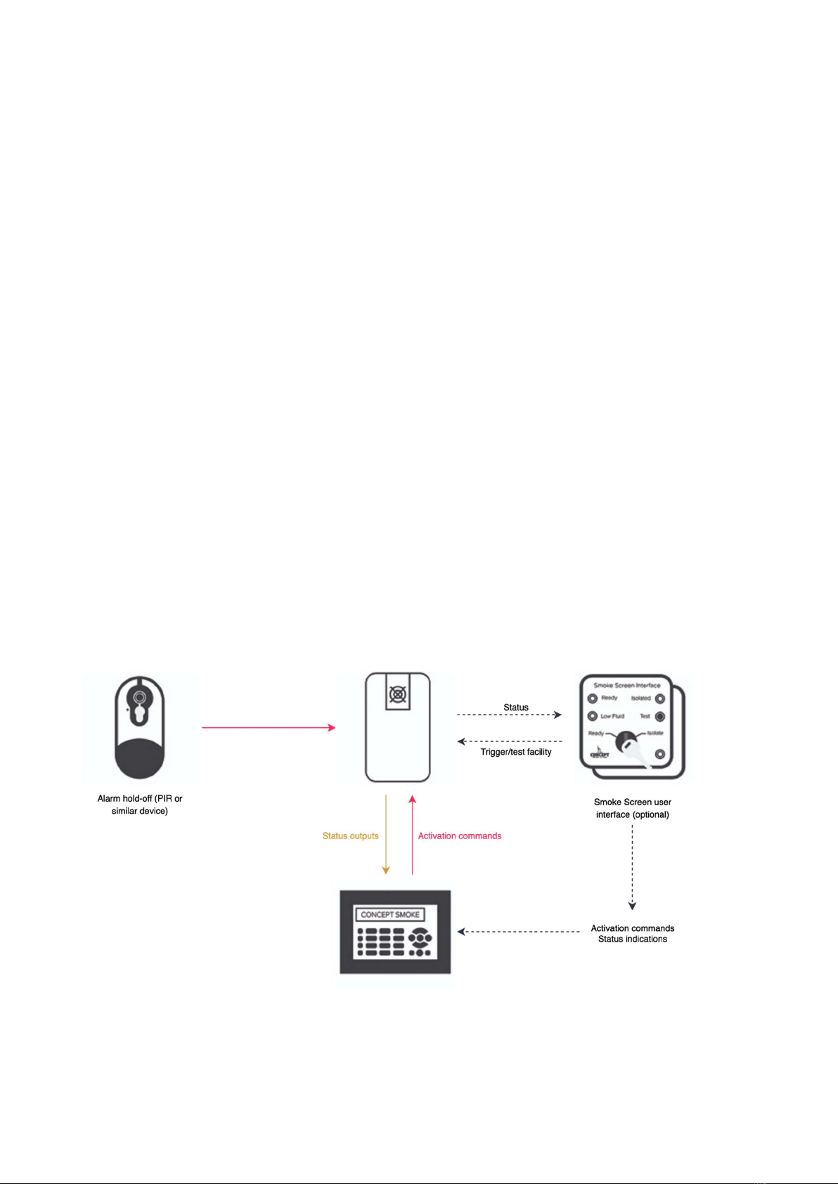
2. Make connections as required to the alarm panel, SSI, hold-off PIR, and PA.
3. Fit batteries, do not switch on yet.
4. If fitted, set the Smoke Screen Interface to ‘isolate’.
5. Select the ‘Service Mode’ dip switch to ‘On’.
6. Change nozzle, if required, before powering up.
7. Connect and turn on the mains power.
8. Turn on the internal battery back-up switch.
9. The Smoke Screen will heat up to operating temperature in approximately 10-15 minutes.
10. Set correct time/date.
11. Set correct smoke timing for the specified room size.
12. if using a Sentinel+, connect an ethernet cable to the module and follow setup instructions.
13. Insert a fluid consumable.
14. Visually test all signals between the Smoke Screen, alarm panel, SSI, hold-off PIR, and PA (as fitted).
15. Confirm alarm panel has full control of the Smoke Screen. With SSI in ‘Ready’ position if fitted.
16. Ensure the ‘Service Mode’ dip switch is selected to ‘Off’.
17. Make sure all tamper switches are closed.
18. Perform activation test.
19. Final check of settings and monitored signals, SSI in ‘Ready’ position if fitted.
2.3 ACCESS
To access the PCB connections, programming panel, mounting holes, batteries, and fluid, remove the front cover by
unscrewing the set screws on either side and unhooking it from the back plate; refitting is the reverse process.
Installation cable entry is through the serrated grommet on the left side of the back plate.
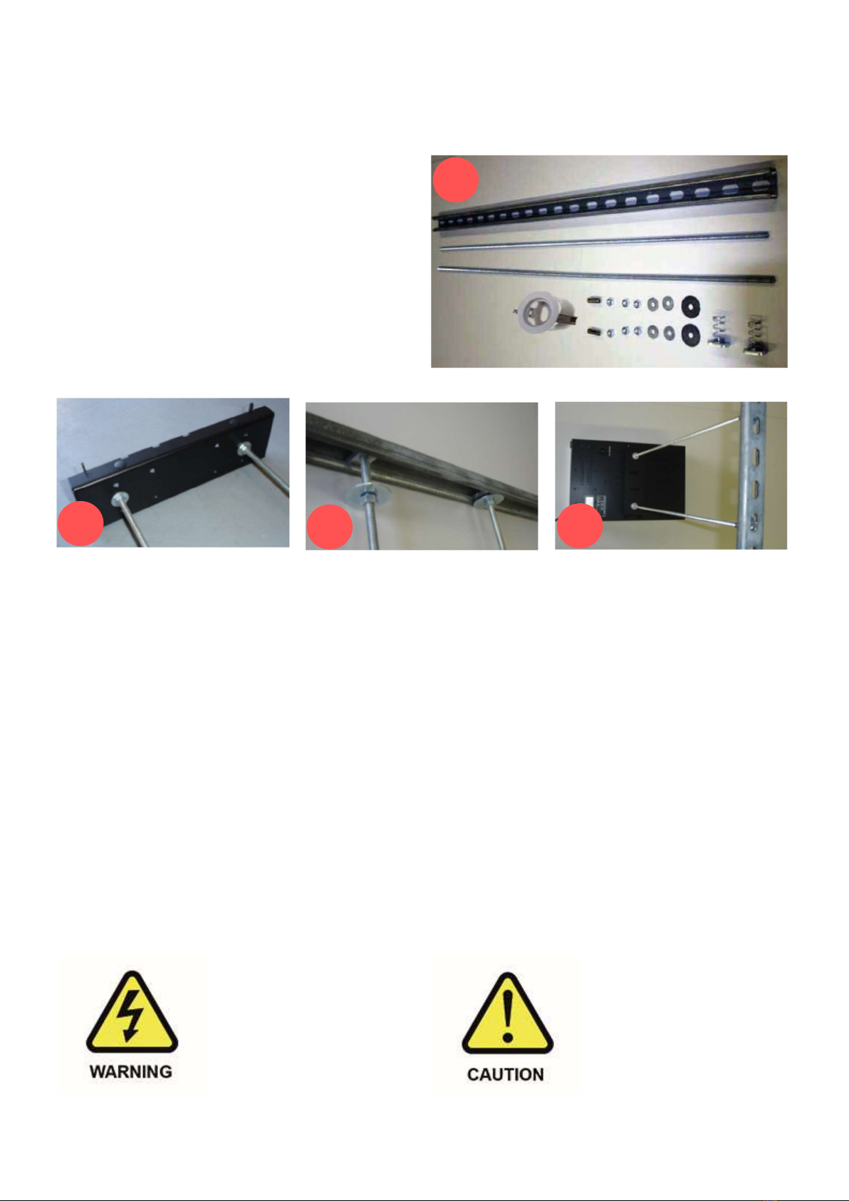
2.4 MOUNTING
The Smoke Screen can be mounted on a ceiling or a wall using the simple standard bracket supplied with the unit.
This flush-fitting bracket maximizes security by concealing all the mounting fastenings such that they can only be
accessed, or the Smoke Screen dismounted, by dismantling the unit. Moreover, the Smoke Screen has a tamper
protection switch to provide an alert in the unlikely event that it is disturbed. In all cases, the installer must attach the
Smoke Screen to the building structure using appropriate fasteners.
NB: When mounting the Smoke Screen ensure that the airflow through the vent holes in the rear of the unit is not
obstructed.
Wall and ceiling mounting
Ceiling or wall mounting is the same process except that rather than fixing the Smoke Screen direct to a ceiling an
intermediate unistrut section may be used or it can be suspended as described in the next section.
a c
b

9
Suspension mounting
Suspending the Smoke Screen is achieved using a ‘Suspension Kit’ comprising a length of unistrut, two sections of
threaded bar and fixings.
Suspension Kit Contents (all M8)
Unistrut 1 x 1 metre
Threaded bar 2 x 1 metre
1 x ceiling hole surround
2 x drop-in anchors
6 x full nuts
4 x 25mm washers
2 x 38mm washers
2 x channel nuts
Prepare the Smoke Screen by fitting
the angle brackets. Fix the required
length of M8 threaded bar to the
bracket using 4 x nuts and 4 x
25mm washers.
Fix the unistrut into place.
There are a range of fixings to
accommodate concrete ceiling,
girders etc. if in doubt contact the
fixing supplier.
Attach the threaded bar to the
unistrut using the channel nuts,
38mm washers and M8 nuts. Once
this is done the Smoke Screen can
be lifted into position and the set
screws tightened as above.
Any fine adjustments can be made
at this stage as the nuts and the
threaded bar will take the weight of
the Smoke Screen.
Any hole made in the ceiling below
can be made good with a cosmetic
hole surround.
Note: Final machine position should
allow an air gap ~50mm above
ceiling tile or when ducting.
2.5 NOZZLE CHANGING
To change the nozzle, first remove the front cover then remove and replace the nozzle using a 10mm ring spanner,
sealing it with PTFE tape and ensuring that an angled nozzle is seated in the correct orientation. The Smoke Screen is
delivered with a single-hole straight nozzle plus an extra 1-hole 30° angle down nozzle. The following are also
available – 2-hole horizontal, 3-hole horizontal, 1-hole 30° angle down and 2-hole 30° angle down.
Be aware of high voltage in the
block area. The electrical supply
should be switched off before
working in the heater block
compartment.
This operation is usually carried out
during installation. If the Smoke
Screen has been in service, the
nozzles will be extremely hot and will
cause injury if touched. Therefore, the
Smoke Screen should be switched off
and time should be allowed for the
nozzles to cool.
g
e f
d

10
Function 3
3.1 CONTROLLING THE SMOKE
Alarm Panel activation
There are 3 sets of inputs on the Smoke Screen (Set, Alarm and Hold-off) that can be connected to clean contacts.
By default, for the Smoke Screen to produce ‘smoke’ all 3 sets of connections must be ‘open circuit’.
We recommend using the default setting ‘Normally Closed’ to ensure that the Smoke Screen will activate in case the
alarm cables are tampered from the outside. These settings can be reversed – see Section 6.5 Inverting Triggers.
• Set – a normally closed relay connected across the alarm panel ‘Set’ output connections, which is open
when the alarm panel is ‘Set’ and closed when the panel is ‘Unset’.
• Alarm – a normally closed relay connected across the alarm panel ‘Intruder’ output connections, which is
open when the alarm panel or controlling device is in ‘Alarm’.
• Optional - Hold-off – usually a PIR / movement sensor normally closed output, which opens when the
sensor detects movement, connected to the Smoke Screen ‘Hold-off’ normally closed connections.
• Additional hold-off – any form of normally closed relay / micro switch / keyswitch can be connected to the
‘Hold-off’ connections. If fitted in parallel to a PIR both devices must be ‘open’ to produce ‘smoke’.
NB: If no ‘hold-off’ is fitted the terminals should be left without anything connected and will show ‘HO’ on the display
as in an active condition.
If a ‘Panic’ output from the alarm system is required to trigger the Smoke Screen we recommend using a DPDT relay
connected to break the Set and Alarm Inputs to the SSI – This allows isolation of the Smoke Screen when testing the
alarm system.
Optional Panic input activation
NB: The Panic trigger mode is delivered set to n/o and the Panic Smoke Time is set to 0 seconds to prevent
inadvertent activation if the facility is not used. ‘Panic Smoke Time’ can be individually set.
The Smoke Screen has a Panic input that can be connected to a clean contact going ‘open circuit’ to activate (this can
be changed to ‘closed = activate’ – see ‘Invert Trigger Mode’ in the Programming section).
It is recommended that the Panic is activated by a momentary, non-latching, button to avoid the situation where a
Panic activation is not reset before a standard activation is required.
WARNINGS:
• Service Mode should be selected to on if the Panic trigger mode is changed when the Smoke
Screen is at operating temperature.
• Always restore a Panic input after it has been used. Failure to do so will result in the Smoke
Screen not subsequently activating on an Alarm Panel (Set, Alarm and Hold-off) demand.

11
Setting ‘Smoke Time’ and ‘Panic Smoke Time’
The Smoke Screen ‘Smoke Time’ should be set to produce fog for a time that is suitable for the volume of the location
to be protected. As a guide, an S70 set to 60 seconds Smoke Time will reduce the visibility to 1 metre* in a 325 m3
volume room. (*EN50131-8 Definition) S100 - 375 m3 / 60 seconds, S150 - 450 m3 / 60 Seconds
The Smoke Screen ‘Panic Smoke Time’ can either be set as a maximum to the same value as above or be used to give
a shorter activation on demand if using a self-resetting PA button for example.
The Smoke Times are changed in the settings menu; see Section 6.10 - Programming
Hold-off settling time – ‘Settle Timer’
A ‘Settle Timer’ can be programmed for a period between 0 and 60 seconds (in 1 second intervals) during which the
Smoke Screen will not react to a hold-off input after receiving a ‘Set’ and ‘Alarm’ command.
Delaying an activation – ‘Smoke Delay’
After the Smoke Screen has received the required 3 inputs to produce smoke, an activation can be delayed for a
period between 0 and 60 seconds (in 1 second intervals). This can be used to sequence activations in a multi-machine
installation. See ‘Smoke Delay’ in section 6.10 - Programming
NB: The Delay Timer and Settle Timer are cumulative, i.e., if a Delay Time of 5 seconds and a Settle Timer of 30
seconds are set: The Smoke Screen will not respond to the ‘Hold Off’ input for 30 seconds after it receives a ‘Set’ and
‘Alarm’ input, it will then delay a further 5 seconds from receiving a ‘Hold-Off’ input before making smoke.
Re-triggering option
If a Smoke Delay time has been set the menu gives the option to select the following options for subsequent re-
triggers initiated by a hold-off if the Set and Alarm remain in alarm: See ‘Retrigger’ in section 6.10 - Programming
• Delay: Repeat activations are delayed by the Delay Time set.
• Instant: Repeat activations are instantaneous.
Stopping an activation
Once activated the Smoke Screen will stop producing ‘smoke’ before the end of the programmed smoke time only if
the ‘Set’ is restored to a non-alarm state.
A Panic activation can only be stopped before the end of the programmed smoke time if the ‘Set’ is cycled to active
and back to restore. This can be performed using the SSI Test Mode.
Preventing an activation
To prevent the Smoke Screen from making smoke during a service inspection under any circumstances select the
‘Service Mode’ dip switch to on (see separate section). NB: Ensure switched off on completion.
3.2 OUTPUTS
Clean contact outputs are provided for connection to the alarm panel for the following:
Mains Fault – Temperature Fault - Fluid Low - Fluid Empty - Battery Fault – Tamper - Verification Output.
A transistorised Set output is also available – 0V when set.
See the notes on the Connection Diagram for the function of these outputs.

12
Sentinel+ 4
Installing the Sentinel+ module
Follow the procedure below if the Sentinel+ module is not fitted on delivery.
Remove the front cover.
Switch off the batteries.
Disconnect the mains power supply.
Fit the Sentinel+ module to the female header sockets on the LCD PCB in the position shown below ensuring
that the pins locate correctly, i.e., the pins line up starting from the left.
Connect ethernet cable.
Switch on the batteries and reconnect the mains power supply.
NB: Installing a Sentinel+ module with power applied to the Smoke Screen may cause the LCD
display to corrupt – pressing the Function menu button should return the display to normal
operation.
Setting up the Sentinel+
See Section 6.10 for information on programming and then make the following entries as required:
By default, the Sentinel+ IP address is set to 0.0.0.0 – This will use DHCP to attempt register onto the network,
if successful the assigned IP address for the unit will be visible under the ‘Telemetry’ setting of LCD display menu.
If a static IP is required, you must manually enter IP address and
subnet mask. You may also need to configure a default gateway
address and a DNS server address. If you are unsure what
settings to use then contact your Network Administrator.
NOTE: When making changes to the network settings, once all
values have been entered - enter the ‘Send Special Command Codes’
menu select ‘Send Command 1’ then ‘Enter’
In a browser enter the IP address, for example: http://192.168.16.84/
The Sentinel+ test page will be shown on the browser.
The Sentinel+ can now be registered for online monitoring. See Section 7.3
The Sentinel can now be remotely programmed if required. See Section 6.11
A simplified device monitoring page is available, for example: http://192.168.16.84/status
Ethernet cable socket.
Note the Ethernet port overhangs the
side of the LCD PCB.

13
Connections 5
5.1 CIRCUIT BOARD LAYOUT

14
5.2 CONNECTION DIAGRAM USING SMOKE SCREEN INTERFACE (Recommended)

15
5.3 CONNECTION DIAGRAM GENERIC

16
Settings 6
6.1 SCREEN SENSOR
A Concept Smoke Screen ‘
Screen Sensor’
can be connected to the Sentinel. When this is integrated the
system detects a drop in the fog density in the protected area and will re-trigger the Sentinel to maintain the
fog level. When fitted the
Screen Sensor
is connected to the Hold Off input pins and, consequently, it
prevents the use of a hold-off detector.
NB: It is critical that the
Screen Sensor
is installed in an area that receives the maximum fog
coverage. It will not operate correctly if this is not achieved
6.2 ENERGY SAVING MODE (ESM)
The Smoke Screen has 3 options for ESM:
• ESM Disable. The Smoke Screen maintains its normal running temperature.
• ESM. When ESM is selected and the alarm panel input to the Smoke Screen is ‘Unset’ the Smoke
Screen lowers its running temperature to a standby level to reduce power consumption and cost.
When the Smoke Screen receives an ‘Alarm Set’ input it automatically heats to its normal operating
temperature.
NB: If the Smoke Screen is in ESM mode and is activated as soon as the alarm is set, i.e., before it
has heated to normal operating temperature, it will still produce smoke but the length of time of the
initial burst of fog will be shortened.
• Extreme. When Extreme is selected and the alarm panel input to the Smoke Screen is ‘Unset’ the
Smoke Screen heater is not operated, and its temperature reduces to ambient. When the Smoke
Screen receives a ‘Set’ input it automatically heats to its normal operating temperature.
NB: This will introduce a period where the Smoke Screen cannot produce fog as it heats up, this will
also report a Temperature Fault (Not Ready) during the heating period.
WARNING: ESM should be disabled if the Smoke Screen is being used with a Panic input.
6.3 VERIFICATION TIMER
If the ‘Verify Timer’ is set to 0 seconds the verification output changes state during an activation for the set
‘Smoke Time’. If the ‘Verify Timer’ is set above the set Smoke Time, the verification output maintains the
changed state for that time after an activation starts.
NB: The Live Status verification display (V) is shown only during the production of fog, not for any
subsequent time set by the ‘Verify Timer’.

17
6.4 SERVICE MODE
Setting dip switch No 4 (see diagram under ‘Circuit Board Layout’) to ‘On’ puts the Smoke Screen into
‘Service Mode’. This setting prevents the Smoke Screen from making smoke whilst work is conducted with
power applied. To highlight that the Smoke Screen is in ‘Service Mode’ the Tamper output is put into an
alarm state.
FAILURE TO DISABLE SERVICE MODE WHEN NO LONGER REQUIRED WILL PREVENT THE
SMOKE SCREEN OPERATING.
6.5 INVERTING TRIGGERS
The Smoke Screen triggers, Set, Alarm, Hold-off and Panic should be connected to clean contacts changing
state in alarm. The triggers can be set to normally closed (N/C) ‘open = activate’ or normally open (N/O)
‘closed = activate’. We recommend using the default setting ‘N/C’ to ensure that the Smoke Screen will
activate in case the alarm cables are tampered from the outside.
The Smoke Screen is delivered with the Set, Alarm and Hold-off triggers set to n/c, i.e., ‘open = activate’.
The Panic trigger is set to n/o to avoid an inadvertent activation if the facility is not used, and the Panic
input is left open.
6.6 TAMPER
There are internal tamper circuits on all the Smoke Screen covers and an external tamper input on PCB
terminal block ‘B’. A ‘Tamper Status’ output is provided on PCB terminal block ‘F’. To prevent unwanted
tamper signals the external tamper input can be disabled if not in use by selecting dip switch 2 to ‘On’,
which bridges the input pins on the PCB.
NB: A tamper ‘open’ state provides only an indication of the event; it does not automatically activate the
Smoke Screen or prevent it from activation.
NB: Tamper output will also be active when ‘Service Mode’ is enabled.
6.7 REBOOT
When the Smoke Screen is in Service Mode the Reboot menu item becomes available. The Smoke Screen
can be rebooted without removing mains and battery power by selecting ‘Yes’. Any settings entered in the
menu will be retained. This facility can be used to clear any critical faults.

18
6.8 FLUID MANAGEMENT
The Smoke Screen has a replaceable 1 litre Swift-Fit fluid reservoir (also known as product code SFL-1000)
that is accessed by removing the cover on the right-hand side of the unit. The fluid level is monitored using
sensors in the fluid reservoir to give a “Low Fluid” indication output when the Swift-Fit is approximately 50%
full and an “Empty Fluid” output when the bottle is empty. The Smoke Screen will not produce fog when
there is an “Empty Fluid” indication.
Be aware of high voltage
in the Smoke Screen. The
mains electrical supply
should be switched off
before changing the fluid
consumable.
If the generator has been
in service the heater block
and connected parts will
be extremely hot and will
cause injury if touched.
Switch off and allow the
heater block to cool.
Changing a fluid consumable
Obtain a replacement fluid reservoir from your Smoke Screen supplier. Open the right-hand access panel.
Lift the reservoir out of the compartment by removing the upper end first.
Disconnect the fluid monitoring cable.
Disconnect the fluid feed pipe (pull collar to release).
Connect the monitoring cable and feed pipe to a
new fluid reservoir.
Insert the reservoir into the fluid compartment base
first ensuring that the pipe connection is not
accidentally released.
Make sure the notch in the reservoir is on the
outside of the Smoke Screen or the compartment
door will not fit. This orientation ensures that the
fluid feed is correct for both upright and face-down
installations.
WARNINGS:

19
WHEN A NEW FLUID CONSUMABLE IS FITTED BATTERY POWER MUST BE APPLIED TO THE SMOKE
SCREEN TO RESET THE ESTIMATED FLUID REMAINING. THE SWIFT FIT HAS ITS OWN BUILT IN FLUID
SENSOR THAT TAKES PRIORITY.
THE SMOKE SCREEN WILL NOT PRODUCE FOG IF THE CONSUMABLE IS NOT CORRECTLY
FITTED.
INSERT FLUID CONSUMABLE WITH CARE: - THE QUICKFIT CONNECTOR CAN BE ACCIDENTALY
DETATCHED OR FLUID LINE KINKED RESULTING IN REDUCED PERFORMANCE.
A SHORT TEST FIRE SHOULD BE PERFORMED AFTER A NEW FLUID CONSUMABLE IS FITTED
External reservoir
A 5000ml external reservoir can be used with Smoke Screen, please contact Concept Smoke Screen if you
wish to use this function.
Other manuals for Sentinel S70
1
This manual suits for next models
2
Table of contents
Other Concept Smoke Screen Security System manuals